

ProductPRODUCT
Featured products
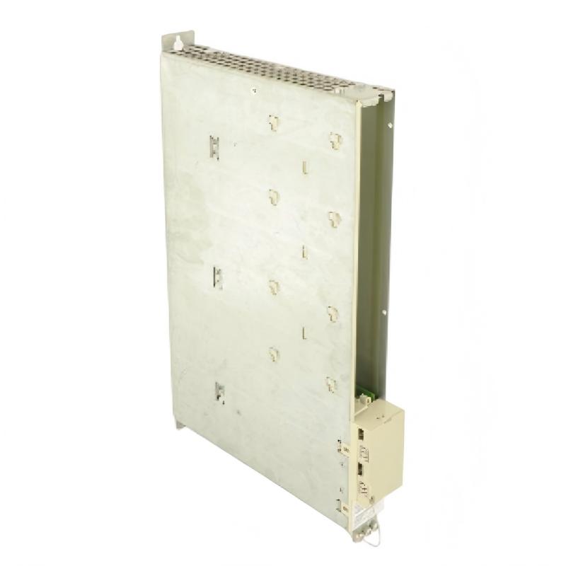
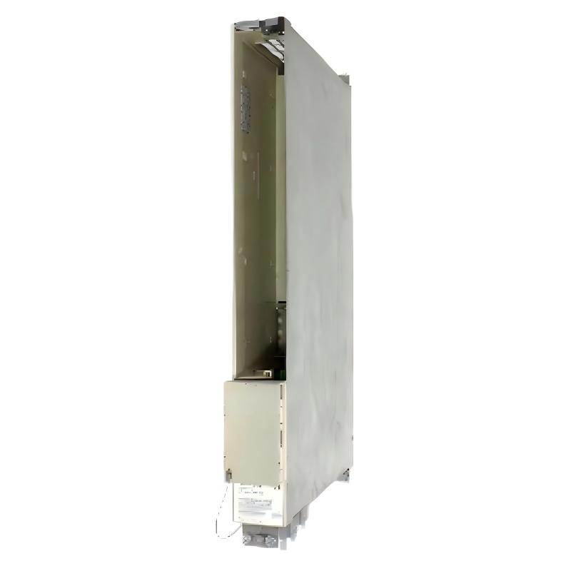
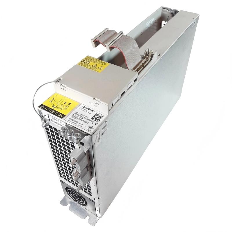
Contact Us
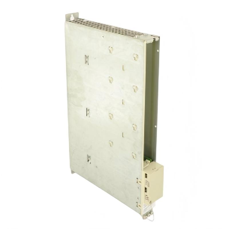
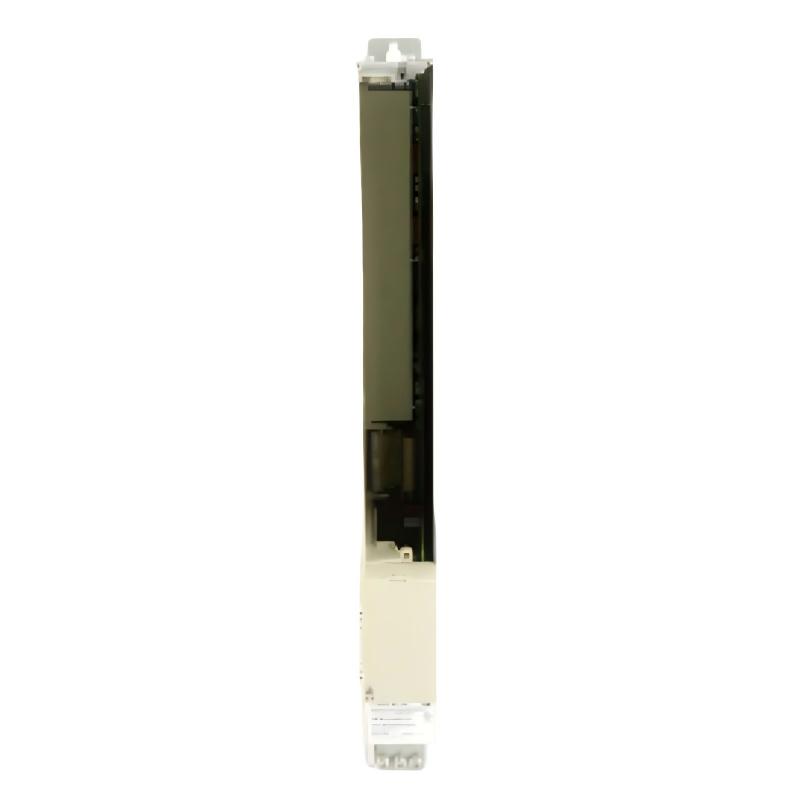
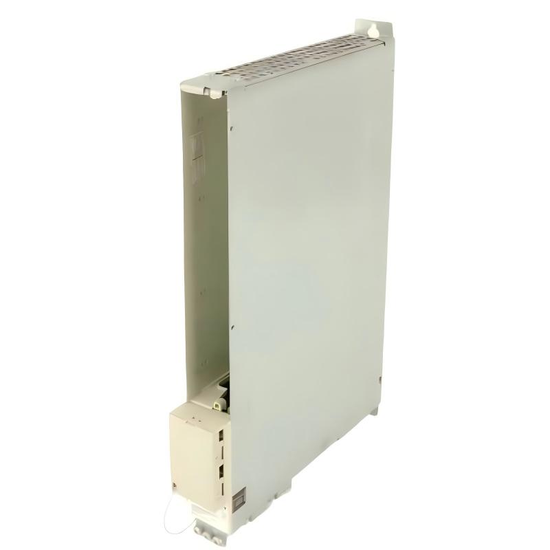
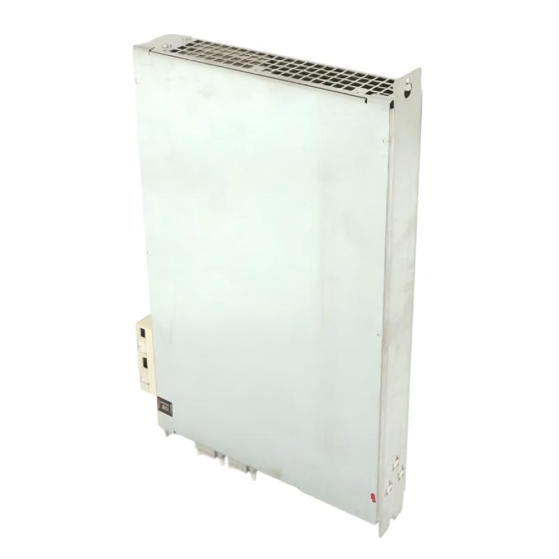
- Siemens
- 6SN1123-1AB00-0HA1
- Power Module
- Germany
- 51 × 483 × 305 mm
- 6 kg
- Xiamen, China
- New & In Stock
- T/T, PayPal, Western Union
- 1 Year
- 1-3 Working Days
- DHL, UPS, TNT, FedEx and EMS.
- 24-Hour Service
- COO
- 3
Our advantage

Global Logistics
We have a 10-year logistics and express cooperation agreement, so our products can be shipped to any place in the world.

Brand new and original
Our products are imported in bulk from the place of origin. Because of the cooperative relationship, our products are all original and 100% new.

24-hour service
We provide 7*24 hours service to our customers. We will be there whenever you need us.

Price advantage
All our products are priced very favorably because we have our own warehouse and supply.
| Company Information | |||
| [email protected] | |||
| Mobile | +8615980777398 | ||
| +8615980777398 | |||
| 15980777398 |
1. Product Overview
The Siemens 6SN1123-1AB00-0HA1 Power Module is an industrial drive-system component associated with Siemens SIMODRIVE equipment. Power modules play an important role in motion-control systems by providing the power-conversion stage required to operate compatible drive motors. They work as part of a larger drive architecture that includes control electronics, motor connections, feedback devices, and protective circuits.
In industrial automation applications, drive-system performance directly affects machine positioning, speed regulation, motion synchronization, and production stability. A correctly selected power module helps the drive system operate within its designed electrical and thermal limits. Compatibility with the installed drive platform is therefore essential when replacing or servicing a module.
The Siemens 6SN1123-1AB00-0HA1 is identified by its complete model number, which should be used for purchasing, maintenance records, and technical verification. The supplied dimensions are 51 × 483 × 305 mm, and the listed weight is 6 kg. These values can support preliminary cabinet-layout planning, handling arrangements, and spare-parts inventory management.
Before installation or replacement, technicians should verify the module’s exact electrical ratings, supported motor configuration, system compatibility, and mounting requirements against the applicable Siemens equipment documentation. The model number alone should not be used to infer unconfirmed current ratings, axis capacity, or connector assignments.
2. Technical Specifications
| Parameter | Specification |
|---|---|
| Brand | Siemens |
| Model Number | 6SN1123-1AB00-0HA1 |
| Product Name | Power Module |
| Product Category | Industrial drive power component |
| Product Family | SIMODRIVE-related drive equipment; confirm exact configuration |
| Dimensions | 51 × 483 × 305 mm |
| Listed Weight | 6 kg |
| Primary Function | Power conversion and motor-drive support within a compatible drive system |
| Installation Environment | Suitable industrial drive cabinet or approved equipment enclosure |
| System Integration | Requires a compatible drive control and power architecture |
| Cooling Requirements | Verify the specified cooling method and airflow requirements |
| Electrical Ratings | Confirm from the exact module documentation |
| Replacement Criteria | Exact model and approved compatibility verification |
The dimensions and weight are based on the supplied product information. Input voltage, output current, supported motor ratings, power dissipation, cooling specifications, and protection characteristics must be verified for the exact module configuration.
3. Function and Working Principle
3.1 Power Conversion for Motion Control
Industrial drive systems convert incoming electrical power into the form required to operate motors. A power module provides a designated part of this process within the drive architecture.
Depending on the overall system configuration, the module works alongside control electronics that determine the required motor operation based on commands, feedback, and machine-control logic. The precise power-conversion topology and supported operating modes must be confirmed for the specified module.
3.2 Supporting Motor Operation
In automated machinery, motors may need to accelerate, decelerate, maintain speed, or execute controlled positioning movements. The power stage supplies the electrical energy required for the drive to produce the commanded motor response.
Stable operation depends on the complete drive system, including the power module, controller, motor, feedback devices, wiring, and protective functions. A fault in any of these components may affect the observed motor behavior.
3.3 Working With Drive Control Electronics
Power modules do not normally operate as independent PLC controllers. They form part of a coordinated drive system in which control electronics manage operating commands, monitor feedback, and supervise faults.
The control unit and power stage must be compatible in terms of hardware configuration, connections, and operating requirements. Incorrect combinations may prevent startup or create fault conditions.
3.4 Thermal Management and Protection
Power electronics generate heat during operation. Appropriate cooling, unobstructed airflow, correct mounting, and a clean installation environment help keep components within their permitted operating range.
Overtemperature conditions may result from inadequate ventilation, excessive load, contamination, cooling-system problems, or internal component failure. The applicable Siemens documentation should be used to determine the module’s thermal limits and maintenance requirements.
4. Role in Industrial Automation Systems
4.1 CNC Machine Tools
Drive power modules are important components in CNC systems that control machine axes and coordinated movement. Correct drive operation helps maintain the intended relationship between commanded motion and actual motor response.
A compatible power module can support stable operation of the associated drive axis when integrated with the correct control hardware and motor.
4.2 Automated Manufacturing Equipment
Automated production machinery often relies on controlled motor movement for material handling, positioning, feeding, and synchronized mechanical operations. Drive-system reliability helps reduce interruptions and maintain production consistency.
The power module must match the machine’s drive configuration and required operating characteristics.
4.3 Motion-Control Applications
In motion-control installations, the drive system responds to commands from a higher-level controller and, where applicable, position or speed feedback from the motor. The power module supports the electrical operation of the drive within this coordinated arrangement.
Incorrect module selection, poor electrical connections, or inadequate cooling can affect the overall performance of the motion-control system.
4.4 Industrial Equipment Maintenance
Keeping an exact replacement module available can help maintenance teams reduce the time needed to restore a compatible drive system after a confirmed module failure.
However, a drive alarm does not automatically indicate that the power module is defective. Proper diagnosis should include the motor, cabling, control unit, power supply, cooling arrangement, and connected mechanical load.
5. Industrial Applications
The Siemens 6SN1123-1AB00-0HA1 Power Module may be relevant to compatible industrial drive installations, subject to confirmation of the exact configuration.
Typical application environments for compatible drive power modules include:
- CNC machining equipment: Supporting controlled movement of machine axes.
- Automated production lines: Providing drive power for designated motion-control functions.
- Industrial positioning systems: Supporting controlled motor movement within an approved drive configuration.
- Machine-building applications: Integrating drive power components into industrial control cabinets.
- Factory automation: Supporting motor-driven equipment coordinated by PLC or CNC control systems.
- Maintenance and retrofit projects: Replacing a confirmed defective module in an existing compatible installation.
These are general application categories for industrial drive power modules, not confirmation that the specified model is suitable for every listed machine. Always verify the installed drive system and exact module compatibility.
6. Installation and System Integration
Installation should be carried out by qualified personnel familiar with industrial drive systems and the applicable electrical safety procedures.
6.1 Verify the Module Before Installation
Before installing the Siemens 6SN1123-1AB00-0HA1, check the following:
- Confirm the complete model number on the module label.
- Verify that the replacement matches the original module or an approved replacement specification.
- Inspect the housing, connectors, terminals, and mounting surfaces for visible damage.
- Confirm the specified input and output electrical requirements.
- Check compatibility with the drive control unit, motor, and associated system components.
- Verify the cooling requirements and available cabinet space.
Do not assume that modules with similar dimensions or neighboring model numbers are interchangeable.
6.2 Isolate the Electrical Supply
Before removing or installing a drive power module, follow the machine’s approved shutdown and lockout/tagout procedures.
Disconnect all relevant power sources and wait for the specified DC-link discharge period. Power electronics may retain hazardous voltage after the main supply has been disconnected. Verify the absence of dangerous voltage using an appropriate instrument and the prescribed procedure before touching electrical connections.
Never rely solely on indicator lights or the elapsed time since shutdown to determine whether a drive is safe to service.
6.3 Inspect the Mounting Area
Check the cabinet, mounting rails or support structure, grounding arrangements, connectors, and surrounding wiring. Remove contamination using an approved method and ensure that ventilation paths are unobstructed.
Inspect nearby components for evidence of overheating, loose connections, damaged insulation, or contamination. If the previous module failed, investigate the underlying cause before installing a replacement.
6.4 Mount the Power Module
Install the module in the designated mounting position and follow the manufacturer’s mechanical installation instructions.
Ensure that the module is properly supported and secured. Do not force connectors or mounting hardware into alignment. Incorrect mounting can create mechanical stress, poor electrical connections, or inadequate cooling.
6.5 Connect the Electrical Interfaces
Reconnect the required power, motor, control, and protective-earth connections according to the specific drive configuration and wiring documentation.
Check connector orientation, terminal assignments, cable condition, shielding, and grounding. Do not rely on generic wiring diagrams or assumptions based on another model.
Verify that all connections are secure and that no loose conductors or foreign objects remain in the cabinet.
6.6 Verify Cooling and Cabinet Conditions
Confirm that the module’s required cooling method is available and that airflow paths are clear. Check cabinet fans, filters, and ventilation openings where fitted.
The actual cooling arrangement must be determined from the exact equipment configuration. Do not assume a particular fan arrangement or cooling direction without the applicable documentation.
6.7 Commission the Drive System
Before restarting the machine, verify the module configuration, control-unit compatibility, motor data, wiring, and protective settings.
Perform the startup and functional checks specified by the equipment manufacturer. Monitor available drive diagnostics and confirm that the system operates within its defined electrical and thermal limits.
Where required, test motor movement at an approved operating condition before returning the machine to normal production.
7. Troubleshooting Common Problems
7.1 Drive Fails to Start
Possible causes:
- Incorrect or incompatible power module.
- Missing or abnormal input power.
- A fault in the control unit or system configuration.
- Loose or incorrectly connected wiring.
- An active protective condition elsewhere in the drive system.
Recommended actions:
- Record the displayed alarm or diagnostic code.
- Check the incoming supply and relevant protective devices.
- Verify the module model and its compatibility with the installed drive.
- Inspect connectors and wiring according to the electrical documentation.
- Check the control unit and related components before concluding that the power module has failed.
All electrical inspections must be performed under the approved safety procedure.
7.2 Overtemperature Alarm
Possible causes:
- Restricted airflow or inadequate cooling.
- Contaminated ventilation paths.
- Excessive load or an abnormal duty cycle.
- High ambient cabinet temperature.
- A cooling-system fault or internal module defect.
Recommended actions:
Inspect the cooling arrangement, cabinet ventilation, and surrounding components. Compare operating conditions with the module’s specified limits. If the alarm persists after the external causes have been addressed, arrange further diagnostic testing.
Do not continue operating the equipment outside its permitted thermal limits.
7.3 Motor Does Not Move Correctly
Possible causes:
- Incorrect motor or drive configuration.
- A problem with motor power wiring.
- Feedback-device or control-signal faults.
- Mechanical obstruction or excessive load.
- A fault in the drive control unit or power stage.
Recommended actions:
Review the drive diagnostics and motor configuration. Check the relevant wiring and feedback signals, and inspect the mechanical system for abnormal resistance. Determine whether the fault originates in the control system, motor, cabling, load, or power module before replacing components.
7.4 Repeated Drive Trips
Possible causes:
- Supply-voltage abnormalities.
- Excessive motor current or mechanical loading.
- Incorrect configuration parameters.
- Poor electrical connections.
- Cooling problems or an internal drive fault.
Recommended actions:
Record the fault codes and operating conditions associated with each trip. Inspect the power supply, motor circuit, cooling system, and connected machinery. Follow the manufacturer’s diagnostic procedure rather than repeatedly resetting the drive without identifying the cause.
7.5 Visible Damage or Signs of Overheating
Possible causes:
- Electrical stress or a short circuit.
- Loose or overheated connections.
- Inadequate cooling.
- Contamination or environmental damage.
- An internal component failure.
Recommended actions:
Isolate the equipment and do not return the module to service until it has been assessed by qualified personnel. Inspect the associated wiring and drive components for secondary damage. A replacement module should not be installed until the cause of the original failure has been investigated.
8. Compatible System Components
The exact components compatible with the Siemens 6SN1123-1AB00-0HA1 must be confirmed using the complete drive configuration and applicable equipment documentation.
| Component Category | Role in the Drive System |
|---|---|
| Drive Control Unit | Provides control functions and coordinates drive operation |
| Motor | Converts electrical energy into mechanical movement |
| Motor Power Cables | Carry electrical power between the drive and motor |
| Feedback Device | Provides position or speed information where required |
| Power Supply or DC-Link Components | Supply the energy required by the drive architecture |
| Protective-Earth Connections | Support electrical safety and grounding |
| Cabinet Cooling Components | Help maintain acceptable operating temperatures |
| PLC or CNC Controller | Provides higher-level machine commands and coordination |
This table describes general drive-system components. It is not a verified compatibility list for the exact module. Check the equipment configuration, connector assignments, electrical ratings, and approved component combinations before purchasing or installation.
9. Replacement and Alternative Selection
Selecting a replacement power module requires careful verification of electrical and mechanical compatibility.
| Selection Option | Recommended Approach |
|---|---|
| Exact replacement | Confirm the complete model number 6SN1123-1AB00-0HA1 |
| Manufacturer-approved replacement | Verify the approved successor or replacement designation |
| Alternative power module | Compare electrical ratings, drive architecture, connectors, cooling, and supported motor configuration |
| Complete drive-system replacement | Consider only when justified by system condition, technical requirements, and an approved engineering assessment |
Before selecting an alternative, verify:
- Exact drive-system and control-unit configuration.
- Input and output electrical ratings.
- Supported motor type and capacity.
- Mechanical dimensions and mounting requirements.
- Electrical connector and terminal assignments.
- Cooling and cabinet requirements.
- Configuration and commissioning requirements.
A power module should not be considered interchangeable solely because its physical dimensions are similar. An unverified substitute can cause startup failures, drive faults, equipment damage, or unsafe operating conditions.
10. Key Advantages of Correct Module Selection
Accurate Product Identification
The full Siemens model number helps maintenance and procurement teams identify the intended component and reduce ordering errors.
Support for Industrial Motion Control
A compatible power module contributes to the operation of the drive system that controls motor movement in industrial machinery.
Maintenance Planning
Maintaining an accurate record of the module model, installation location, and replacement history supports troubleshooting and spare-parts management.
Improved System Integration
Verifying the module against the installed control unit, motor, wiring, and cooling arrangement helps reduce compatibility problems during replacement.
Reduced Downtime Risk
Keeping an approved replacement available can help maintenance teams respond more efficiently to a confirmed module failure.
11. Technical FAQs
Q1: What is the Siemens 6SN1123-1AB00-0HA1?
It is identified as a Siemens Power Module associated with industrial drive equipment. Its precise function and compatibility should be confirmed against the exact drive-system documentation.
Q2: What are the dimensions of this power module?
The supplied dimensions are 51 × 483 × 305 mm.
Q3: What is the listed weight?
The listed weight is 6 kg.
Q4: Can this module be used with any Siemens SIMODRIVE system?
No. Compatibility depends on the specific drive architecture, control unit, electrical ratings, motor configuration, and hardware requirements.
Q5: What information should be checked before purchasing a replacement?
Confirm the complete model number, electrical ratings, control-unit compatibility, motor configuration, connectors, cooling requirements, and approved replacement status.
Q6: Does a drive fault always indicate a defective power module?
No. Faults may originate from the power supply, motor, feedback system, control unit, wiring, cooling system, or mechanical load. Diagnosis should be completed before replacing the module.
Q7: What safety precautions are required during replacement?
Qualified personnel should isolate the equipment, follow lockout/tagout procedures, observe the specified DC-link discharge period, and verify the absence of dangerous voltage before servicing the module.
Q8: Can a power module with similar dimensions be used as a substitute?
Not without technical verification. Electrical ratings, connector arrangements, control compatibility, and cooling requirements must also match the approved system design.
Q9: What should be checked after installation?
Verify wiring, grounding, mounting, cooling, system configuration, and relevant drive diagnostics. Perform the specified functional tests before returning the machine to normal operation.
12. Conclusion
The Siemens 6SN1123-1AB00-0HA1 Power Module is an industrial drive-system component identified by its complete Siemens model number. The supplied dimensions are 51 × 483 × 305 mm, and the listed weight is 6 kg.
Correct selection, installation, cooling, and commissioning are essential to reliable operation in a compatible drive system. Maintenance personnel should verify the module’s electrical specifications, control-unit compatibility, motor configuration, and approved replacement status before installing it.
For industrial automation engineers, equipment maintenance teams, and spare-parts distributors, accurate model identification and systematic troubleshooting help reduce replacement errors, support maintenance planning, and improve the reliability of industrial motion-control equipment.