

ProductPRODUCT
Featured products
Contact Us
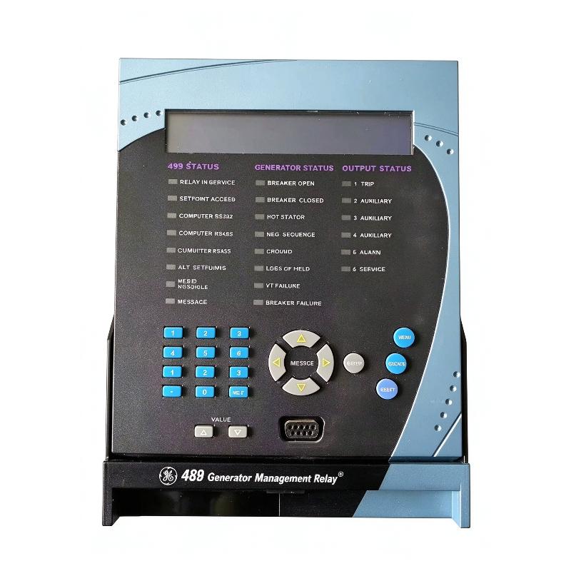
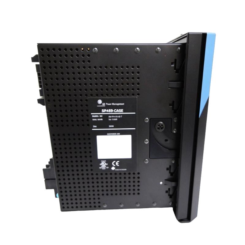
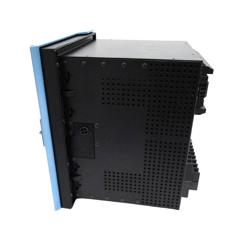
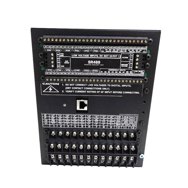
- GE
- SR489-P5-LO-A20-E
- Generator Management Relay
- USA
- 252 × 216 × 224 mm
- 7.7 kg
- Xiamen, China
- New & In Stock
- T/T, PayPal, Western Union
- 1 Year
- 1-3 Working Days
- DHL, UPS, TNT, FedEx and EMS.
- 24-Hour Service
- COO
- 5
Our advantage

Global Logistics
We have a 10-year logistics and express cooperation agreement, so our products can be shipped to any place in the world.

Brand new and original
Our products are imported in bulk from the place of origin. Because of the cooperative relationship, our products are all original and 100% new.

24-hour service
We provide 7*24 hours service to our customers. We will be there whenever you need us.

Price advantage
All our products are priced very favorably because we have our own warehouse and supply.
| Company Information | |||
| [email protected] | |||
| Mobile | +8615980777398 | ||
| +8615980777398 | |||
| 15980777398 |
Product Overview
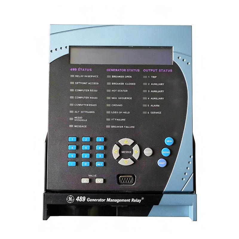
The GE SR489-P5-LO-A20-E Generator Management Relay is part of the GE Multilin 489 generator protection and management family. It combines electrical protection, metering, temperature monitoring, alarm handling and trip control in a drawout relay package for synchronous and induction generator applications.
This configuration uses 5 A phase current transformer inputs, a low-range control power supply and 4–20 mA analog outputs. The low-range power supply accepts 24–60 V DC or 20–48 V AC at 48–62 Hz. The enhanced-display option provides a larger LCD and an improved keypad for local access to relay measurements, status information and settings.
The relay evaluates electrical measurements and connected condition signals against configured protection settings. Depending on the application and enabled functions, it can operate assigned trip and alarm outputs when abnormal generator conditions are detected. Serial communications also support integration with compatible monitoring and engineering systems.
Technical Specifications
| Parameter | Specification |
|---|---|
| Manufacturer | GE |
| Model / Order Number | SR489-P5-LO-A20-E |
| Product Family | GE Multilin 489 |
| Product Type | Generator Management Relay |
| Phase CT Input Rating | 5 A |
| Control Power Option | LO |
| DC Control Power Input | 24–60 V DC |
| AC Control Power Input | 20–48 V AC |
| AC Control Power Frequency | 48–62 Hz |
| Analog Output Option | A20 |
| Analog Output Range | 4–20 mA |
| Display Option | Enhanced display with larger LCD and improved keypad |
| Output Relays | 6 |
| Digital Inputs | 9 opto-isolated inputs |
| RTD Monitoring | Supports up to 12 RTD inputs |
| Communication Interfaces | RS232 and RS485 |
| Communication Protocols | Modbus RTU, DNP 3.0 |
| Protection Functions | Configurable generator electrical and thermal protection |
| Enclosure / Mounting Format | Drawout relay package |
| Dimensions | 252 × 216 × 224 mm |
| Weight | 7.7 kg |
Product Features
- Generator protection: Provides configurable protection functions for abnormal electrical and operating conditions in generator systems.
- 5 A phase CT inputs: Matches applications using current transformers with 5 A secondary outputs.
- Low-range control power: Supports 24–60 V DC or 20–48 V AC supply options.
- 4–20 mA analog outputs: Transmits configured measurements to compatible monitoring and control equipment.
- Enhanced local display: Provides a larger LCD and improved keypad for viewing operating values and relay status.
- RTD temperature monitoring: Supports connected temperature sensors for generator stator, bearing and other configured monitoring points.
- Electrical metering: Provides generator measurements for operating assessment and supervisory monitoring.
- Trip and alarm outputs: Allows configured protection elements to activate assigned output relays.
- Serial communication: Supports data exchange with compatible supervisory systems and engineering tools.
- Drawout construction: Supports relay withdrawal for inspection and testing when the equipment is safely isolated and the prescribed procedure is followed.
Working Principle
The SR489-P5-LO-A20-E receives generator current and voltage signals from connected instrument transformers. Its processing system evaluates these measurements against programmed settings for enabled protection functions, which may include overcurrent, voltage abnormalities, frequency deviations, reverse power and thermal overload conditions.
Temperature sensors and other configured inputs provide additional operating information. When a measured condition meets the pickup threshold and timing requirements of a protection element, the relay can activate the assigned trip or alarm outputs. The relay also records relevant event information to help maintenance personnel investigate abnormal operation.
The A20 option provides 4–20 mA analog outputs. Each output can be configured to represent a supported measured parameter, allowing selected generator values to be transmitted to compatible meters, controllers or plant monitoring equipment.
The LO control power option determines the auxiliary supply range required by the relay. Correct current-transformer wiring, voltage-transformer configuration, protection settings and output assignments are essential to ensure that the relay responds as intended.
Role in a Generator Protection and Control Architecture
The GE Multilin 489 serves as a dedicated protection and monitoring device between the generator’s measurement circuits, breaker-control circuitry and plant supervision system. It evaluates signals locally and issues configured trip or alarm commands when programmed conditions are satisfied.
| System Component | Function | Relationship to the Relay |
|---|---|---|
| Generator Current Transformers | Provide scaled generator current signals | Supply phase-current measurements matching the 5 A input configuration |
| Voltage Transformers | Provide generator voltage signals | Supply voltage measurements for configured protection and metering |
| RTD Temperature Sensors | Measure generator and bearing temperatures | Supply thermal information to configured monitoring functions |
| Generator Circuit Breaker | Connects or isolates the generator | Receives trip commands through the assigned control circuit |
| Alarm and Annunciation System | Alerts operators to abnormal conditions | Receives configured relay alarms or associated status information |
| Plant PLC or SCADA System | Supervises equipment and displays operating values | Exchanges supported measurements and status information |
| Engineering Computer | Configures relay settings and retrieves diagnostics | Connects through supported communication interfaces and software |
| Auxiliary Control Power Supply | Powers the relay | Must meet the LO option’s specified AC or DC input range |
Industrial Applications
| Application | Protection or Monitoring Task | Role of the Relay |
|---|---|---|
| Industrial Generator Sets | Monitoring generator electrical conditions | Evaluates configured protection elements and operates assigned trip or alarm outputs |
| Standby Power Systems | Supervising generator operation during backup service | Provides generator protection and operating measurements |
| Combined Heat and Power Plants | Monitoring generators operating alongside plant loads | Consolidates protection, metering and diagnostic information |
| Industrial Power Stations | Detecting electrical and thermal operating abnormalities | Supports configured generator protection and alarm handling |
| Cogeneration Systems | Monitoring generator output and connected temperature signals | Provides electrical measurements and condition monitoring |
| Generator Control Panels | Integrating protection with breaker and operator interfaces | Connects instrument-transformer inputs, control outputs and supervisory communication |
Installation and Maintenance
- Verify the complete order code: Confirm that SR489-P5-LO-A20-E matches the required current input, control power, analog output and display configuration.
- Check panel mounting requirements: Verify that the panel opening, case arrangement and installation clearances match the applicable mounting documentation.
- Confirm auxiliary power: Ensure that the supply is within the LO option’s range of 24–60 V DC or 20–48 V AC at 48–62 Hz.
- Inspect current transformer wiring: Confirm the 5 A secondary rating, phase identification, polarity and grounding arrangements before connecting the current inputs.
- Verify voltage transformer connections: Check the voltage wiring, phase relationships, transformer ratios and corresponding relay settings.
- Check digital input circuits: Verify that external contacts and status signals are connected to the intended opto-isolated inputs.
- Test analog output loops: Confirm that receiving equipment supports 4–20 mA signals and that output scaling and loop wiring are correct.
- Inspect RTD connections: Verify sensor types, terminal assignments and wiring for configured stator or bearing temperature monitoring.
- Review protection settings: Check generator ratings, CT and VT ratios, trip thresholds, time delays and output-relay assignments before commissioning.
- Verify communication configuration: Check RS232 or RS485 wiring, protocol selection, baud rate and device addressing where applicable.
- Perform functional testing: Test measurement scaling, alarms, trip logic, output contacts and breaker-interface circuits under an approved commissioning procedure.
- Document the final configuration: Record the relay order code, control power range, protection settings, communication parameters and functional test results.
Compatible System Components
| Component | Function | Compatibility Consideration |
|---|---|---|
| Phase Current Transformers | Supply generator phase-current signals | Match the relay’s 5 A secondary input and configured CT ratios |
| Ground Current Transformer | Supplies ground-fault current information | Select a supported arrangement for the enabled ground-protection function |
| Voltage Transformers | Supply generator voltage signals | Verify secondary ratings, connection type and programmed ratio |
| RTD Temperature Sensors | Monitor stator, bearing or other configured temperatures | Confirm sensor type and wiring compatibility |
| Generator Circuit Breaker Trip Circuit | Opens the breaker when a configured trip operates | Verify trip-coil ratings and the complete control-circuit design |
| 4–20 mA Analog Input | Receives the relay’s analog signals | Confirm input range and parameter scaling at the receiving device |
| RS485 Communication Network | Carries serial data between devices | Configure compatible communication settings and protocol |
| Plant PLC or SCADA System | Supervises generator status and measurements | Map required values using supported communication functions |
Recommended Related Models
| Model | Product Type | Relationship | Selection Consideration |
|---|---|---|---|
| GE Multilin 489-P1-LO-A20-E | Generator Management Relay | Related configuration with 1 A phase CT inputs and low-range control power | Use only where the connected phase CT secondary rating calls for the P1 option |
| GE Multilin 489-P5-HI-A20-E | Generator Management Relay | Related configuration with 5 A phase CT inputs and high-range control power | Compare the required auxiliary supply range |
| GE Multilin 489-P5-LO-A1-E | Generator Management Relay | Related configuration with 5 A phase CT inputs and 0–1 mA analog outputs | Consider when the receiving equipment requires the A1 output range |
| GE Multilin 489-P5-LO-A20-T | Generator Management Relay | Related configuration with 5 A phase CT inputs, low-range power and enhanced display with Ethernet | Check the Ethernet requirement and complete order-code configuration |
Key Advantages
- Combines generator protection, metering and monitoring functions in one relay.
- Supports 5 A phase current transformer inputs.
- Accepts low-range AC or DC auxiliary power.
- Provides configurable 4–20 mA analog outputs.
- Supports RTD-based temperature monitoring and programmable protection logic.
- Offers local display, event information and serial communication for maintenance and supervision.
Technical FAQs
What does the LO option mean in the SR489-P5-LO-A20-E?
The LO option specifies the low-range control power supply. It accepts 24–60 V DC or 20–48 V AC at 48–62 Hz, so the installed auxiliary supply must match these requirements.
Which current transformer secondary rating does the P5 configuration use?
The P5 option is for phase current transformers with 5 A secondary outputs. The connected CT ratios and phase wiring must be entered correctly in the relay settings.
What does the A20 option provide?
A20 specifies 4–20 mA analog outputs. These can be assigned to supported generator measurements so compatible external equipment can receive scaled operating data.
What should be checked if the relay issues an unexpected trip?
Review the event record, enabled protection elements, measured values, pickup thresholds, time delays and output assignments. Also verify CT and VT wiring and the programmed transformer ratios before changing protection settings.