

ProductPRODUCT
Featured products
Contact Us
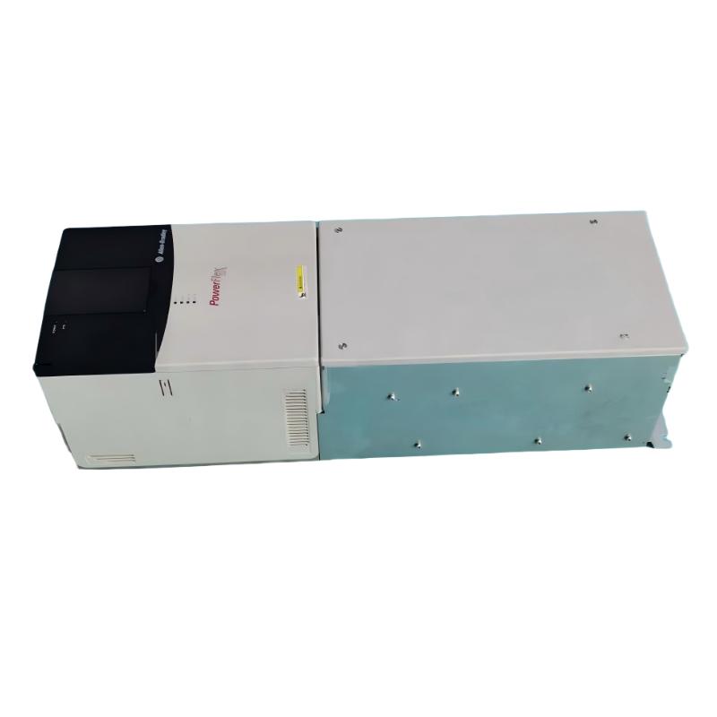
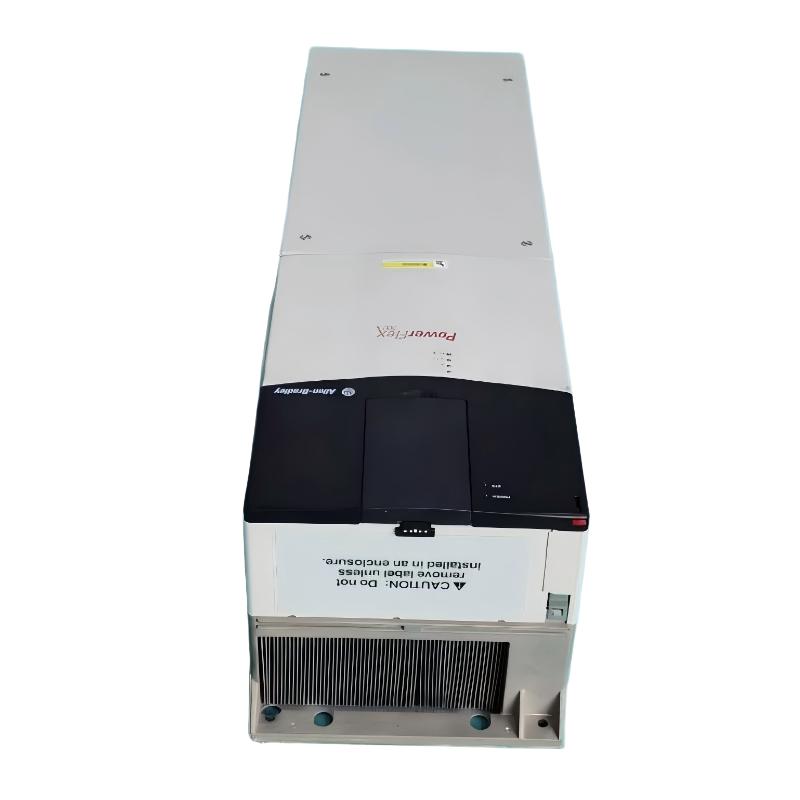
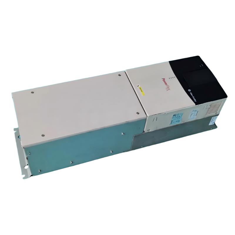
- Allen Bradley
- 20BC105A0ANNANN0
- PowerFlex AC Drive
- USA
- 220.0 × 758.8 × 201.7 mm
- 42.9 kg
- Xiamen, China
- New & In Stock
- T/T, PayPal, Western Union
- 1 Year
- 1-3 Working Days
- DHL, UPS, TNT, FedEx and EMS.
- 24-Hour Service
- COO
- 5
Our advantage

Global Logistics
We have a 10-year logistics and express cooperation agreement, so our products can be shipped to any place in the world.

Brand new and original
Our products are imported in bulk from the place of origin. Because of the cooperative relationship, our products are all original and 100% new.

24-hour service
We provide 7*24 hours service to our customers. We will be there whenever you need us.

Price advantage
All our products are priced very favorably because we have our own warehouse and supply.
| Company Information | |||
| [email protected] | |||
| Mobile | +8615980777398 | ||
| +8615980777398 | |||
| 15980777398 |
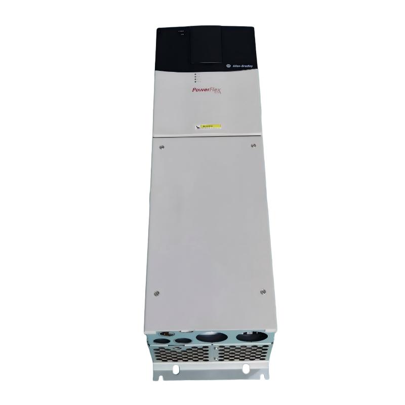
Allen-Bradley 20BC105A0ANNANN0 Variable Frequency Drive: Product Specifications, Features, Applications, and Model Recommendations
1. Product Overview
The Allen-Bradley 20BC105A0ANNANN0 is an industrial variable frequency drive (VFD) associated with the PowerFlex 700 AC drive family. Variable frequency drives are used to control the speed, torque, acceleration, and deceleration of AC motors in industrial automation systems.
This type of drive is designed for applications in which motors need more flexible control than conventional direct-on-line starting can provide. By regulating the electrical frequency and voltage supplied to the motor, the drive can support controlled starting, adjustable operating speeds, and smoother stopping. These functions are particularly useful in production equipment, material handling systems, pumps, fans, and machinery that operates under changing load conditions.
The 20BC105A0ANNANN0 is an alphanumeric catalog number. Its individual characters identify configuration options, so the complete catalog number should be retained when checking compatibility, ordering replacement equipment, or preparing a technical specification.
The description below focuses on the product family, its typical industrial functions, selection considerations, and related model recommendations. Exact electrical ratings, enclosure dimensions, and shipping or net weight should be verified against the specific hardware revision before they are used for installation or procurement.
2. Brand and Product Series
|
Item |
Description |
|---|---|
|
Brand |
Allen-Bradley |
|
Product model |
20BC105A0ANNANN0 |
|
Product family |
PowerFlex 700 |
|
Product category |
Variable frequency drive / AC motor drive |
|
Main function |
Variable-speed control of AC motors |
|
Industrial application |
Factory automation and motor control |
|
Typical control functions |
Speed adjustment, acceleration and deceleration control, motor protection, operating monitoring |
|
Installation environment |
Industrial electrical cabinets or an appropriate industrial installation |
|
Control system integration |
Compatible integration depends on the installed drive options and control interface |
|
Replacement selection |
Requires comparison of voltage, current, enclosure, hardware options, firmware, and connection requirements |
2.1 Brand Characteristics
Allen-Bradley is an established industrial automation brand associated with motor control, programmable controllers, operator interfaces, and factory automation equipment.
Its motor drive products are used in applications where production equipment needs repeatable speed control, reliable motor operation, and integration with a wider automation system. Drive selection is generally based on the motor nameplate, supply voltage, required output current, operating environment, control method, and communication requirements.
2.2 Product Series: PowerFlex 700
The PowerFlex 700 series is an industrial AC drive family intended for applications requiring adjustable motor speed and more comprehensive control than a basic standalone speed controller.
Depending on the particular model and installed options, drives in this family can provide:
-
Adjustable motor speed and operating frequency.
-
Controlled acceleration and deceleration.
-
Motor overload and drive fault monitoring.
-
Adjustable operating parameters for different machine loads.
-
Local operator control and remote control through suitable interfaces.
-
Integration with industrial automation systems using supported control and communication options.
-
Diagnostic information to assist maintenance personnel with troubleshooting.
The exact functions available on an individual unit depend on its hardware configuration, installed options, firmware, and associated accessories.
3. Detailed Technical Specifications of 20BC105A0ANNANN0
The following table summarizes the principal technical characteristics of the specified drive. Values identified as configuration-dependent or unverified should not be treated as confirmed nameplate ratings.
|
Parameter |
Specification |
|---|---|
|
Model |
20BC105A0ANNANN0 |
|
Brand |
Allen-Bradley |
|
Product series |
PowerFlex 700 |
|
Product type |
AC variable frequency drive |
|
Rated input voltage |
400 V AC nominal |
|
Input voltage range |
380–480 V AC drive class |
|
Input phase |
Three-phase |
|
Output phase |
Three-phase |
|
Rated output current |
105 A |
|
Motor power, normal duty |
55 kW |
|
Motor power, heavy duty |
45 kW |
|
Mains frequency |
50 Hz nominal |
|
Maximum output frequency |
Up to 400 Hz for the specified product listing; confirm the unit’s configuration |
|
Typical efficiency |
Approximately 97.5% at rated current and nominal line voltage |
|
Enclosure classification |
IP20 / NEMA Type 1 |
|
Protective coating |
Conformal coating specified |
|
EMC filtering |
Second-environment filter configuration |
|
Integrated brake transistor |
Not fitted |
|
Drive-mounted braking resistor |
Not included |
|
Operator interface |
No HIM; blank plate configuration |
|
Communication module |
No internal communication module specified |
|
Control configuration |
Standard control |
|
Built-in I/O |
No I/O specified in the exact catalog configuration |
|
Feedback interface |
No feedback option specified |
|
Ambient temperature |
Maximum rating depends on installation conditions and derating requirements |
|
Maximum altitude without derating |
Typically 1,000 m for this drive family; verify installation requirements |
|
Cooling method |
Internal forced-air cooling, subject to hardware configuration |
|
Dimensions (H × W × D) |
Exact dimensions not confirmed; consult the mechanical drawing for the complete catalog number |
|
Net weight (kg) |
Exact net weight not confirmed; obtain the applicable mechanical specification |
|
Mounting method |
Industrial cabinet or suitable panel mounting, subject to clearance and mounting instructions |
|
Product lifecycle |
Legacy product family; confirm current availability and replacement suitability |
3.1 Electrical Input and Output
The drive belongs to the 400 V AC class and is intended for three-phase industrial electrical supplies. Its 105 A current rating and 55 kW normal-duty rating make it suitable for a range of medium-to-high-power industrial motor applications, provided that the motor, load, supply, and installation conditions are compatible.
The input voltage, supply frequency, motor nameplate voltage, and required output current should all be checked before commissioning. A drive that matches a motor’s power rating may still be unsuitable if the voltage, current, overload profile, or environmental requirements differ.
3.2 Motor Power and Load Ratings
The product’s specified power ratings distinguish between normal-duty and heavy-duty operation.
|
Load rating |
Power rating |
Typical selection consideration |
|---|---|---|
|
Normal duty |
55 kW |
Suitable for applications whose operating current and overload demand remain within the normal-duty rating |
|
Heavy duty |
45 kW |
Intended for applications with more demanding torque or overload requirements, within the specified limits |
|
Rated current |
105 A |
Must be checked against motor full-load current and the drive’s applicable rating conditions |
Normal-duty applications may include machinery with relatively steady torque demand. Heavy-duty applications can include equipment that requires higher starting torque or more demanding short-term overload performance.
The distinction is important: motor selection should not be based on kilowatts alone. Current, torque, acceleration time, starting frequency, and the actual load profile all affect the appropriate drive rating.
3.3 Control and Interface Configuration
The catalog description identifies a standard-control configuration with no built-in I/O specified and no internal communication module.
This matters when integrating the drive into a machine. An installation that relies on hardwired start/stop commands, analog speed references, or a fieldbus connection may require additional interface hardware or a different catalog configuration.
Before selecting a replacement, check the existing control cabinet’s wiring, communication architecture, speed-reference method, fault-reset arrangement, and operator-interface requirements.
3.4 Enclosure and Environmental Protection
The IP20 / NEMA Type 1 classification is intended for suitable industrial indoor installations, typically within a protective electrical enclosure or an appropriate electrical installation.
It should not be interpreted as a rating for direct exposure to rain, washdown, conductive dust, or corrosive liquids. The conformal coating offers additional protection for circuit boards against certain environmental stresses, but it does not make the entire drive waterproof or suitable for every corrosive environment.
Proper ventilation, cabinet temperature control, dust management, and clearance around the cooling system are important for long-term operation.
3.5 Dimensions and Weight
Physical dimensions and weight are essential when planning a replacement, designing an electrical cabinet, calculating mounting loads, or arranging transportation.
For this exact model, the verified height, width, depth, and net weight are not established here. They should not be estimated from a visually similar PowerFlex 700 model because frame size, options, and hardware revisions can affect mechanical details.
|
Mechanical parameter |
Specification |
|---|---|
|
Height (mm) |
Not confirmed |
|
Width (mm) |
Not confirmed |
|
Depth (mm) |
Not confirmed |
|
Net weight (kg) |
Not confirmed |
|
Shipping weight (kg) |
Not confirmed |
|
Mounting-hole spacing |
Confirm using the applicable dimension drawing |
|
Required ventilation clearance |
Follow the installation instructions for the exact frame |
|
Cabinet heat dissipation |
Calculate using the applicable drive loss data |
|
Lifting and handling requirements |
Confirm from the product’s mechanical documentation |
For procurement, the safest approach is to obtain the dimensional drawing and shipping specification for the exact catalog number, rather than use an approximate figure. This is particularly important when the replacement must fit into an existing cabinet without modification.
4. Product Introduction and Operating Principle
The 20BC105A0ANNANN0 is intended to regulate the operation of an AC motor by controlling the electrical power delivered to it. Instead of allowing the motor to run only at a speed determined by the supply frequency and motor characteristics, a variable frequency drive provides an adjustable operating frequency and corresponding voltage control.
This enables equipment to operate at a speed appropriate to the production process. A conveyor can run more slowly during loading, a fan can adjust airflow to demand, and a machine can accelerate gradually instead of applying full operating speed immediately.
A typical variable frequency drive performs three main electrical functions:
1. Rectification: Converts incoming AC power into a DC electrical link.
2. DC-link energy management: Uses internal electrical components to maintain the DC link required by the inverter.
3. Inversion: Uses power electronic switching to produce a variable-frequency, variable-voltage AC output for the motor.
The drive’s control system adjusts the output according to the programmed parameters, command signals, and operating conditions.
The result is more flexible motor operation, with the potential to improve process control, reduce unnecessary mechanical stress, and lower energy consumption in applications where motor speed can be reduced to match demand.
5. Main Product Features
5.1 Adjustable Motor Speed
The drive allows the motor’s operating speed to be adjusted to meet production requirements. Speed can be set through supported control methods, subject to the installed hardware and parameter configuration.
This is useful when a machine needs different operating speeds for different materials, production stages, or process conditions.
5.2 Controlled Acceleration and Deceleration
Acceleration and deceleration ramps can help reduce abrupt mechanical loading during starting and stopping.
On conveyors, mixers, and similar equipment, gradual acceleration can reduce sudden tension changes and limit mechanical shock. Appropriate ramp settings must still account for the load’s inertia and the machine’s stopping requirements.
5.3 Motor and Drive Monitoring
The PowerFlex 700 family supports operating monitoring and fault diagnostics. Depending on configuration, relevant information may include current, frequency, operating status, and fault conditions.
These functions can help maintenance staff distinguish between an electrical supply problem, a motor overload, a control-command issue, or another drive-related fault.
5.4 Industrial Automation Integration
PowerFlex 700 drives can be incorporated into larger automation systems using supported control interfaces and optional communication hardware.
However, the specified catalog configuration does not include an internal communication module and has no I/O specified. Additional hardware or a differently configured model may therefore be necessary for a particular installation.
5.5 Conformal Coating
The specified product configuration includes conformal coating. This coating can provide a protective layer over electronic assemblies, helping reduce the effects of certain environmental contaminants.
Its protection is limited to the conditions for which the equipment is designed. It does not replace appropriate cabinet sealing, temperature control, maintenance, or compliance with installation requirements.
5.6 High-Power Industrial Motor Control
With a listed rating of 105 A, 55 kW normal duty, and 45 kW heavy duty, the drive is intended for industrial equipment with substantial motor-power requirements.
Its suitability for a particular machine must be determined by the motor’s actual current demand, operating torque, overload requirements, supply characteristics, and cooling conditions.
6. Product Applications
The 20BC105A0ANNANN0 is best considered for industrial machinery where adjustable motor speed, controlled acceleration, and repeatable operation are important.
6.1 Conveyor and Material Handling Systems


Conveyor systems often operate under changing production requirements. A variable frequency drive can adjust belt speed, coordinate movement between production stages, and reduce sudden mechanical loading during startup.
Typical applications include:
-
Manufacturing assembly lines.
-
Packaging and sorting conveyors.
-
Material transfer systems.
-
Industrial feeding equipment.
-
Production-line transport machinery.
For conveyor applications, the drive rating should be checked against the load’s starting torque, belt inertia, and required acceleration time. Systems that stop frequently or carry heavy loads may require a more demanding duty rating than a continuously operating conveyor.
6.2 Pumps and Fluid Handling Equipment


Pumps are often selected to deliver a required flow rate or pressure. When the process permits speed variation, a drive can adjust motor speed to match changing demand.
Potential applications include:
-
Industrial water circulation.
-
Process-fluid transfer.
-
Cooling-water systems.
-
Industrial utility pumping.
-
Water treatment equipment.
Variable-speed operation may reduce energy consumption when flow requirements vary. The actual savings depend on the pump curve, system resistance, operating hours, and control strategy.
For pump installations, the engineer should also consider minimum operating speed, cavitation risk, motor cooling, pressure-control requirements, and the possibility of water hammer during changes in operating conditions.
6.3 Fans and Ventilation Systems


Industrial fans and blowers frequently operate for long periods. Where airflow demand changes throughout the day, adjustable speed can help match output to process requirements.
Potential applications include:
-
Factory ventilation.
-
Industrial exhaust systems.
-
Process-air circulation.
-
Dust extraction equipment.
-
Cooling-air systems.
Fan loads can offer meaningful energy-saving opportunities because the power required by many centrifugal fan systems decreases substantially as speed is reduced. However, the result depends on the fan design, duct resistance, operating point, and system control method.
6.4 Mixing and Processing Machinery
Mixers, agitators, and processing machines often require different speeds during different stages of operation.
A drive can provide controlled speed changes for material blending, liquid circulation, and other processes. The appropriate configuration depends on the viscosity of the material, the torque profile, the required mixing speed, and the frequency of starting and stopping.
6.5 Industrial Production Equipment
Other potential applications include auxiliary production machinery, selected machine tools, processing lines, and equipment used in general manufacturing.
Before installation, confirm that the drive’s control performance, output current, motor compatibility, and protection arrangements are suitable for the specific machine.
7. Main Product Advantages
|
Advantage |
Description |
Practical benefit |
|---|---|---|
|
Adjustable speed |
Allows motor speed to be matched to process requirements |
Greater flexibility in production |
|
Controlled starting |
Provides adjustable acceleration ramps |
Can reduce mechanical shock |
|
Controlled stopping |
Allows the stopping profile to be configured |
More predictable machine operation |
|
Industrial power rating |
Rated at 105 A for the specified configuration |
Suitable for appropriately sized industrial motors |
|
Process flexibility |
Supports variable operating speeds |
Helps accommodate changing production conditions |
|
Drive diagnostics |
Provides drive-status and fault information |
Can simplify troubleshooting |
|
Potential energy savings |
Reduces speed where the process permits |
May reduce electricity consumption |
|
Conformal coating |
Adds protection to electronic assemblies |
Helps in suitable industrial environments |
|
Configurable integration |
The product family supports different control arrangements |
Can be adapted to a range of machine designs |
|
Maintenance familiarity |
Established industrial drive architecture |
May simplify servicing where technicians already know the platform |
7.1 Improved Process Control
A fixed-speed motor can be limiting when the production process requires frequent speed changes. A drive enables the operating speed to be adjusted according to material flow, machine throughput, or production timing.
This can be particularly useful when a single machine performs multiple operations or when production demand changes throughout a shift.
7.2 Reduced Mechanical Stress
Sudden starting and stopping can place additional stress on couplings, belts, gears, shafts, and driven machinery.
Appropriately configured acceleration and deceleration ramps can make transitions smoother. The actual mechanical benefit depends on the machine’s inertia, load characteristics, and control settings.
7.3 Potential Energy Savings
Energy savings are most likely when a motor can run below full speed for meaningful periods without compromising the process.
Pumps and centrifugal fans are common examples. By contrast, applications requiring constant full output or high torque at low speed may offer fewer savings, and additional motor cooling may be necessary at reduced speeds.
7.4 More Flexible Machine Design
A variable frequency drive allows machine designers to consider operating-speed requirements as part of the control system rather than relying solely on mechanical speed changes.
This can reduce the need for some mechanical adjustment methods, although the suitability of the approach depends on the application.
7.5 Better Maintenance Visibility
Drive status and fault information can help technicians investigate abnormal operation. When combined with appropriate monitoring and maintenance procedures, this can support more systematic fault diagnosis.
A drive does not eliminate the need to inspect motors, bearings, wiring, cooling systems, or the driven machine itself.
8. Five Recommended Models from the Same Series or Related Configurations
The following five recommendations focus on the PowerFlex 700 family and related configurations. Two are identifiable catalog variants in the same 400 V, 105 A class; the remaining entries are selection targets within the series rather than verified exact catalog numbers.
Important: Similar-looking catalog numbers can represent materially different electrical and control configurations. Where a complete orderable catalog number or physical specification has not been verified, it is explicitly identified as a selection target.
|
No. |
Recommended model or selection target |
Series |
Main electrical parameters |
Control and configuration |
Dimensions (H × W × D) |
Weight (kg) |
|---|---|---|---|---|---|---|
|
1 |
20BC105A0ANNANA0 |
PowerFlex 700 |
400 V AC, 3-phase, 105 A, 55 kW normal duty / 45 kW heavy duty |
Standard control; 24 V I/O; no feedback; no internal communication module |
Not confirmed |
Not confirmed |
|
2 |
20BC105A0ANNANC0 |
PowerFlex 700 |
400 V AC, 3-phase, 105 A, 55 kW normal duty / 45 kW heavy duty |
Vector-control configuration; 24 V I/O; no feedback; no internal communication module |
Not confirmed |
Not confirmed |
|
3 |
PowerFlex 700, 400 V class, lower-current configuration |
PowerFlex 700 |
380–480 V class; current and motor power depend on selected catalog number |
Select to match the motor’s current, overload duty, and control requirements |
Depends on selected model |
Depends on selected model |
|
4 |
PowerFlex 700, 400 V class, higher-current configuration |
PowerFlex 700 |
380–480 V class; higher-current version to be selected from the applicable rating table |
Intended for evaluation where the existing motor load exceeds the 105 A rating |
Depends on selected model |
Depends on selected model |
|
5 |
PowerFlex 700, feedback-equipped configuration |
PowerFlex 700 |
Voltage and current depend on the selected catalog number |
Consider when closed-loop speed or other supported feedback functions are required |
Depends on selected model |
Depends on selected model |
8.1 Recommendation 1: 20BC105A0ANNANA0
This is a closely related catalog variant in the same PowerFlex 700 product family and 105 A rating class.
Its listed electrical ratings are the same as the target model, while the control configuration specifies 24 V I/O. It may be worth considering when a replacement project requires a comparable power rating but needs a different control-interface arrangement.
The main checks are the actual terminal arrangement, I/O requirements, braking provisions, communications, and mechanical fit.
8.2 Recommendation 2: 20BC105A0ANNANC0
This catalog variant retains the same general voltage, current, and motor-power ratings but specifies vector control with 24 V I/O.
It may be worth evaluating for applications where the required motor-control method differs from the standard-control configuration. Compatibility must be established through the motor-control requirements and the existing control-system design.
8.3 Recommendation 3: Lower-Current PowerFlex 700
A lower-current version of the PowerFlex 700 family may be appropriate if the motor being controlled is smaller than the original application requires.
A lower-rated drive may reduce equipment cost and cabinet requirements, but the selection should be based on the motor’s full-load current and load profile rather than power alone.
8.4 Recommendation 4: Higher-Current PowerFlex 700
A higher-current version should be evaluated if the application requires more current than the 105 A model can supply.
The replacement must also match the incoming voltage, overload requirements, available cabinet space, cooling arrangements, and control-system interface.
8.5 Recommendation 5: Feedback-Equipped PowerFlex 700
Some motor-control applications require feedback for improved speed regulation or other supported control functions.
For such applications, a feedback-equipped configuration may be worth evaluating. The appropriate feedback hardware and control capability must be confirmed for the exact drive and application.
These five recommendations are not interchangeable without engineering checks. The first two have identifiable catalog numbers; the remaining three describe configuration choices rather than confirmed orderable part numbers.
9. Five Popular Allen-Bradley Models for Comparison
The following table covers five widely recognized drive models or product families for different industrial motor-control needs. They are alternatives to consider, not direct replacements for the 105 A PowerFlex 700.
Because their exact ratings depend on the selected catalog number, frame, and option set, the table separates general family characteristics from model-specific electrical specifications. Physical dimensions and weights are not stated as confirmed where the precise catalog number has not been selected.
|
No. |
Model |
Product series |
Typical voltage class |
Current and power parameters |
Typical application |
Dimensions (H × W × D) |
Weight (kg) |
|---|---|---|---|---|---|---|---|
|
1 |
25B-D017N104 |
PowerFlex 525 |
480 V class |
Catalog-specific current and power rating; verify the exact nameplate and rating table |
General machinery and conveyors |
Not confirmed for this configuration |
Not confirmed |
|
2 |
25B-D024N104 |
PowerFlex 525 |
480 V class |
Catalog-specific current and power rating; verify the exact nameplate and rating table |
Pumps, fans, and machine automation |
Not confirmed for this configuration |
Not confirmed |
|
3 |
20F11NC015JA0NNNNN |
PowerFlex 753 |
400 V class, subject to catalog configuration |
Current and power depend on the selected rating and options |
Industrial process and machine control |
Not confirmed for this configuration |
Not confirmed |
|
4 |
20G11NC022JA0NNNNN |
PowerFlex 755 |
400 V class, subject to catalog configuration |
Current and power depend on the selected rating and options |
More demanding industrial motor-control applications |
Not confirmed for this configuration |
Not confirmed |
|
5 |
22B-D017N104 |
PowerFlex 40 |
480 V class |
Catalog-specific current and power rating; verify the exact nameplate and rating table |
Compact industrial machinery and simple speed control |
Not confirmed for this configuration |
Not confirmed |
Model-selection caution: The part numbers above are comparison candidates, not confirmed drop-in replacements. Their electrical ratings and suffix-dependent options must be checked before ordering. In particular, a compact drive such as a PowerFlex 525 or PowerFlex 40 should not be assumed capable of replacing a 105 A PowerFlex 700.
9.1 PowerFlex 525
The PowerFlex 525 family is commonly considered for general-purpose industrial motor control where compact installation and flexible machine integration are priorities.
It may suit smaller conveyors, pumps, fans, and auxiliary machinery. Its suitability as a replacement for the target model depends on the required current, power, control functions, and installation design.
9.2 PowerFlex 753
The PowerFlex 753 family is designed for industrial motor-control applications that may require more advanced configuration and integration options.
It can be a candidate for larger machinery and process applications, provided that the selected unit’s ratings, available options, and control interfaces meet the requirements.
9.3 PowerFlex 755
The PowerFlex 755 family is intended for demanding industrial motor-control applications with a broader range of configuration and integration possibilities.
It is worth evaluating when a project requires a modernized drive architecture or additional control capabilities. The exact model must still be sized to the motor and application.
9.4 PowerFlex 40
The PowerFlex 40 is a compact general-purpose AC drive family used in smaller motor-control applications.
It can be appropriate for simpler machines where its available current, power, and control functions are sufficient. It is not automatically suitable for a 55 kW normal-duty application.
9.5 Choosing Between These Families
|
Selection factor |
PowerFlex 700 |
PowerFlex 525 |
PowerFlex 753 |
PowerFlex 755 |
PowerFlex 40 |
|---|---|---|---|---|---|
|
General role |
Industrial AC motor control |
Compact general-purpose control |
Industrial process and machine control |
Advanced industrial motor control |
Compact general-purpose control |
|
Suitability for 55 kW normal duty |
Depends on the exact rating; the target model is rated 55 kW |
Verify the selected catalog number and current rating |
Select an appropriately rated configuration |
Select an appropriately rated configuration |
Do not assume suitability; verify rating |
|
Cabinet replacement |
Potentially favorable when matching the original configuration |
Mechanical redesign may be needed |
Mechanical redesign may be needed |
Mechanical redesign may be needed |
Mechanical redesign may be needed |
|
Existing wiring reuse |
Requires terminal and control comparison |
Requires terminal and control comparison |
Requires terminal and control comparison |
Requires terminal and control comparison |
Requires terminal and control comparison |
|
Communication compatibility |
Depends on installed options |
Depends on model and configuration |
Depends on installed options |
Depends on installed options |
Depends on model and configuration |
|
Main selection priority |
Match the original electrical and control design |
Compact installation and suitable power rating |
Industrial process requirements |
Advanced control requirements |
Simpler, lower-power applications |
10. Installation and Commissioning Considerations
Correct installation is essential for safe operation and long service life.
10.1 Confirm the Motor Nameplate
Record the motor’s rated voltage, full-load current, rated frequency, power, speed, and connection arrangement.
The drive’s voltage and current ratings must be appropriate for the motor and load. Do not use the drive’s maximum output frequency as the normal operating frequency without confirming that the motor and driven equipment can safely operate at the selected speed.
10.2 Verify the Power Supply
Confirm the three-phase supply voltage, frequency, available fault current, protective devices, and grounding arrangements.
The installation should comply with applicable electrical standards and the drive’s installation instructions. Input protection and conductor sizing should be based on the exact configuration and installation conditions.
10.3 Check Cooling and Cabinet Space
The drive produces heat during operation. Cabinet ventilation and cooling capacity must be sufficient to maintain acceptable operating temperatures.
Allow for the specified clearance around the drive and avoid arrangements that recirculate hot exhaust air into the cooling inlet. Where multiple drives are installed in the same cabinet, evaluate the combined heat load.
10.4 Configure Motor Parameters
Before operating the motor, enter the required motor nameplate parameters and set suitable acceleration, deceleration, speed limits, and protection settings.
Incorrect parameters can result in poor motor performance, nuisance trips, excessive current, or unsafe machine behavior.
10.5 Confirm Control and Communication Requirements
The specified 20BC105A0ANNANN0 configuration has no I/O specified and no internal communication module. Therefore, the actual control arrangement must be checked carefully.
Determine whether the machine requires local commands, hardwired remote control, analog references, a fieldbus, feedback devices, or other interfaces. Any necessary interface hardware should be included in the replacement design.
10.6 Review Braking Requirements
The target model is specified without an integrated brake transistor and without a drive-mounted braking resistor.
If the application requires rapid deceleration or handles a regenerative load, assess the braking requirements separately. The appropriate solution depends on the load inertia, stopping time, duty cycle, and available braking hardware.
10.7 Establish a Maintenance Plan
A suitable maintenance plan should include inspection of ventilation passages, cooling fans, electrical connections, signs of overheating, contamination, and drive fault history.
Maintenance intervals should be determined from the operating environment, duty cycle, installation conditions, and the applicable product instructions.
11. Procurement Checklist
Before ordering the target model or a related alternative, the following information should be confirmed.
|
Checkpoint |
Required information |
Why it matters |
|---|---|---|
|
Catalog number |
Complete part number and hardware revision |
Prevents configuration mismatch |
|
Input voltage |
Actual three-phase supply voltage |
Ensures electrical compatibility |
|
Motor current |
Full-load current and operating current |
Prevents drive undersizing |
|
Motor power |
Rated motor power and duty requirements |
Helps establish an appropriate drive rating |
|
Control method |
Standard control, vector control, or another required method |
Determines motor-control suitability |
|
I/O requirements |
Digital and analog signals needed |
Ensures the machine can be controlled |
|
Communications |
Required industrial network and protocol |
Avoids integration problems |
|
Braking |
Required stopping time and braking method |
Ensures the drive can meet the application’s demands |
|
Enclosure |
IP rating and cabinet requirements |
Supports environmental suitability |
|
Dimensions |
Verified height, width, and depth |
Confirms cabinet fit |
|
Weight |
Verified net and shipping weight |
Supports mounting and logistics planning |
|
Lifecycle and availability |
Current availability and suitable engineering replacement |
Helps manage long-term maintenance |
|
Accessories |
Required filters, interface modules, and other options |
Ensures the complete system is functional |
12. Final Recommendation
The 20BC105A0ANNANN0 is a 400 V-class PowerFlex 700 AC drive rated at 105 A, with a stated motor-power rating of 55 kW for normal duty and 45 kW for heavy duty. Its configuration includes conformal coating, an IP20 / NEMA Type 1 enclosure classification, no operator HIM, no integrated brake transistor, no internal communication module, and no I/O specified.
For a like-for-like replacement, begin by comparing the target model with 20BC105A0ANNANA0 and 20BC105A0ANNANC0. Although these variants share the same general voltage, current, and power ratings, their control and interface configurations differ.
For a broader modernization project, PowerFlex 753 and PowerFlex 755 are worth evaluating when their control capabilities and available configurations match the machine’s requirements. PowerFlex 525 and PowerFlex 40 are more appropriate to consider for applications whose current and power demands fit those families.
Finally, the exact physical dimensions and net weight of the target model have not been confirmed in this specification. Those values should be obtained from the mechanical drawing and product documentation before cabinet redesign, shipping calculations, or installation planning.