

ProductPRODUCT
Featured products
Contact Us
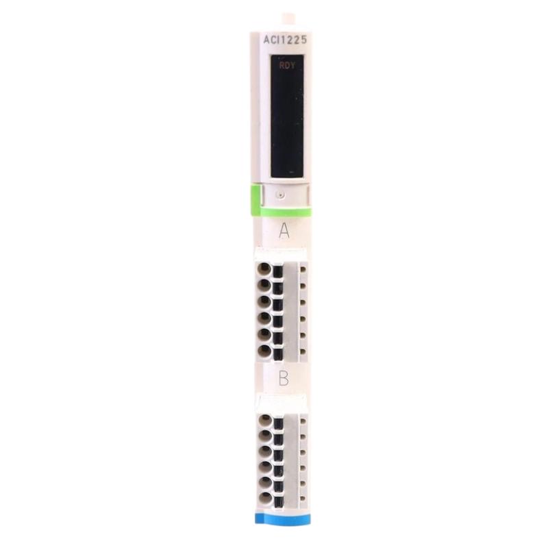
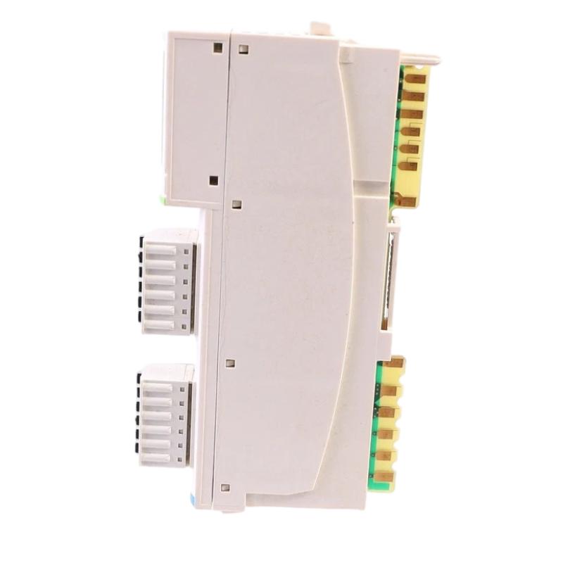
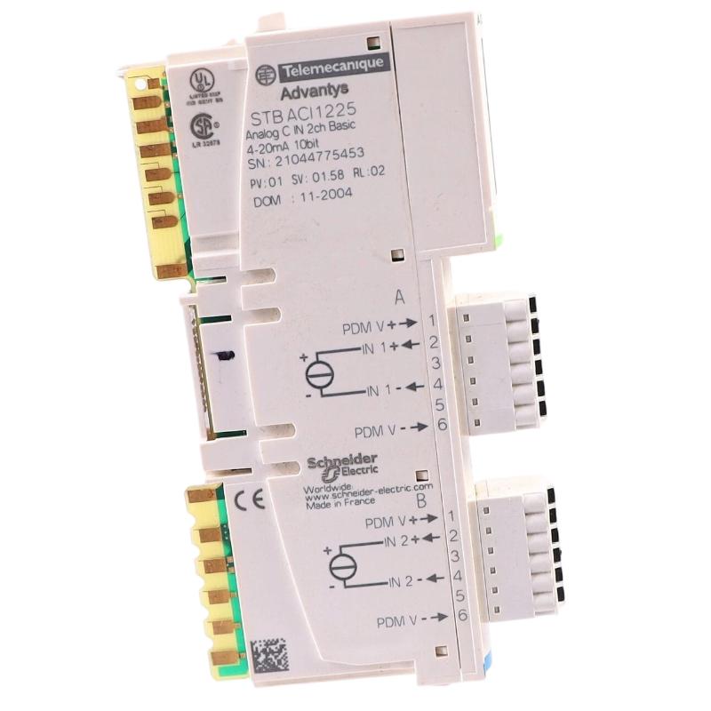
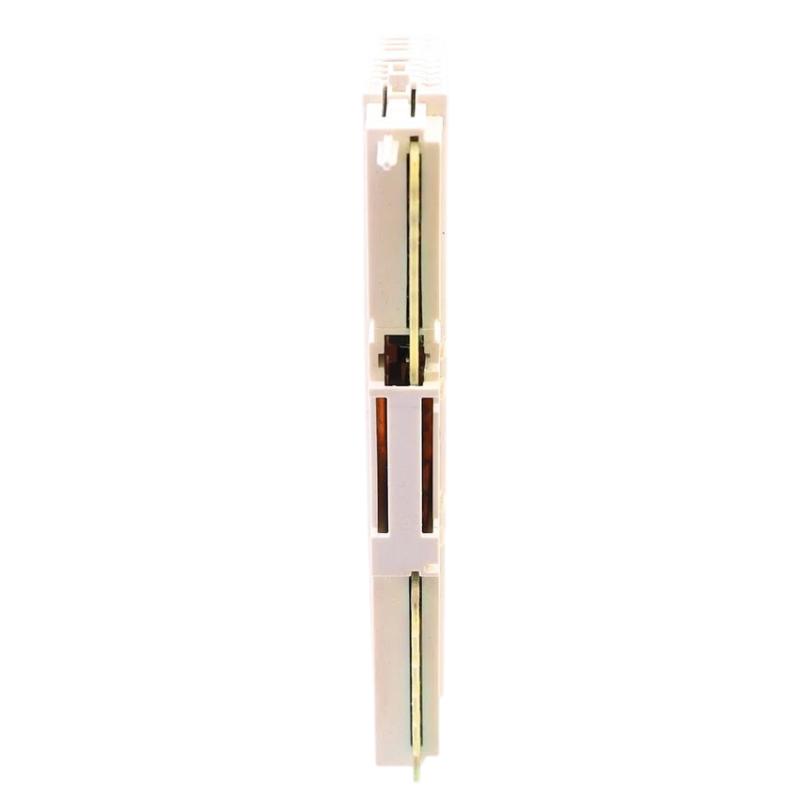
- Schneider
- STBACI1225K
- Basic Analog Input Kit
- France
- 13.9 x 128.3 x 70 mm
- 0.02 kg
- Xiamen, China
- New & In Stock
- T/T, PayPal, Western Union
- 1 Year
- 1-3 Working Days
- DHL, UPS, TNT, FedEx and EMS.
- 24-Hour Service
- COO
- 4
Our advantage

Global Logistics
We have a 10-year logistics and express cooperation agreement, so our products can be shipped to any place in the world.

Brand new and original
Our products are imported in bulk from the place of origin. Because of the cooperative relationship, our products are all original and 100% new.

24-hour service
We provide 7*24 hours service to our customers. We will be there whenever you need us.

Price advantage
All our products are priced very favorably because we have our own warehouse and supply.
| Company Information | |||
| [email protected] | |||
| Mobile | +8615980777398 | ||
| +8615980777398 | |||
| 15980777398 |
Product Overview
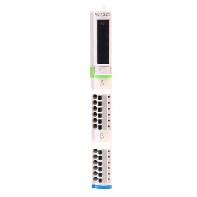
The Schneider Electric STBACI1225K Basic Analog Input Kit is an industrial automation component identified for analog signal acquisition within compatible Schneider Electric control systems. Analog input interfaces enable a controller to receive measurement information from field instruments and use that information for process monitoring, equipment control, and automated decision-making.
Unlike digital input devices, which generally represent discrete ON/OFF states, analog input systems handle signals that represent changing process values. Depending on the instrument and interface configuration, these values may correspond to pressure, temperature, flow, level, or other continuously varying operating conditions. A compatible analog input module allows the controller to interpret these signals as usable process data.
The STBACI1225K is associated with the Schneider Electric Advantys STB distributed I/O product family. Its supplied dimensions are 13.9 × 128.3 × 70 mm, and its supplied weight is 0.02 kg. These physical specifications are useful for preliminary inventory and installation planning, although the actual mounting arrangement and kit contents should be verified before replacement or commissioning.
The term “Basic Analog Input Kit” should be checked against the complete product identification and the installed system configuration. In particular, the exact analog signal types, channel count, electrical characteristics, and required terminal accessories must be confirmed for the specific hardware combination rather than assumed from the product name alone.
Technical Specifications
| Parameter | Specification |
|---|---|
| Manufacturer | Schneider Electric |
| Model / Part Number | STBACI1225K |
| Product Type | Basic Analog Input Kit |
| Product Family | Advantys STB distributed I/O family |
| Primary Function | Analog signal acquisition for compatible automation systems |
| Signal Category | Analog input; supported signal types require verification |
| System Role | Interface between field instrumentation and control logic |
| Dimensions | 13.9 × 128.3 × 70 mm |
| Weight | 0.02 kg |
| Installation | Compatible Advantys STB arrangement; verify exact mounting requirements |
| Typical Applications | Process monitoring, industrial instrumentation, and automated control |
| Compatibility | Confirm against the exact module, terminal base, network interface, and system configuration |
The specifications above distinguish the supplied physical data from details that require confirmation. The listed dimensions and weight are reproduced as provided. The kit’s precise contents and electrical ratings should be established using its complete product documentation and the existing installation.
What Is the Schneider STBACI1225K?
The STBACI1225K is identified as an analog input kit intended for use in an industrial automation environment. Analog input hardware is important when a control system needs to monitor measured process variables rather than simply detect whether a switch is open or closed.
Industrial transmitters and measuring instruments convert physical conditions into electrical signals. A compatible input interface receives those signals and makes the resulting measurement information available to the control system. The controller can then compare the measurements with configured limits, display process values, generate alarms, or use the data in a control algorithm.
For example, a pressure transmitter may provide a signal representing pressure in a pipeline. The control system can use the corresponding measurement to monitor operating conditions or regulate a process through other compatible control equipment.
A simplified signal path is:
Process Variable → Field Instrument → Analog Input Interface → Controller → Monitoring or Control Response
The exact signal path depends on the field instrument, the installed analog input hardware, the distributed I/O architecture, and the controller configuration.
Function and Working Principle
1. Analog Signal Acquisition
The primary purpose of an analog input system is to receive electrical signals representing changing process conditions. Depending on the supported interface, the field signal may be a current or voltage signal from a compatible transmitter.
Common industrial measurement applications include pressure monitoring, temperature measurement, liquid-level monitoring, and flow measurement. The STBACI1225K should only be connected to signal types explicitly supported by the verified hardware configuration.
2. Signal Conditioning and Conversion
Analog measurement systems generally require electrical signal conditioning and conversion before the controller can use the data. Depending on the specific module design, these functions may include input protection, filtering, signal scaling, and analog-to-digital conversion.
The exact implementation and performance characteristics must be confirmed for the installed product. Measurement accuracy, resolution, conversion time, isolation, and input impedance should not be inferred from the product family alone.
3. Measurement Data Transfer
Once a measurement has been acquired, the compatible distributed I/O system makes the input data available to the controller through the configured system architecture.
In a distributed automation installation, the input interface may be located near the field instruments, while the main controller is installed elsewhere. This arrangement can help organize field wiring and support modular system design.
The communication path and supported network interfaces depend on the associated Advantys STB components and the host control system.
4. Process Monitoring
The controller can use acquired measurements to display current operating values, track process changes, or compare measurements with configured thresholds.
For example, a process-control program may generate an alarm when a measured pressure exceeds a permitted operating range. The input interface supplies measurement information; the control program determines how the system responds.
5. Closed-Loop Control Support
When integrated into a suitable control strategy, analog measurements can be used as feedback for regulating pumps, valves, drives, heaters, and other equipment. A controller may compare a measured value with a target and adjust a compatible output accordingly.
The STBACI1225K should therefore be viewed as one component of a larger automation system, not as a standalone process controller.
Role in Schneider Electric Advantys STB Systems
Distributed I/O systems allow field signals to be collected through modular interface hardware and transferred to a compatible controller. The Advantys STB architecture is designed around modular I/O arrangements, with system capabilities depending on the modules, bases, network interface, power distribution, and controller used.
Within a suitable configuration, an analog input component can support the acquisition of process measurements needed for supervisory monitoring or automatic regulation.
A typical distributed I/O arrangement may include:
- Field transmitters and measuring instruments
- Analog input hardware
- Compatible terminal or mounting components
- Distributed I/O communication interface
- Appropriate power-distribution components
- PLC or process controller
- HMI or supervisory monitoring software
- Output interfaces and final control devices
The exact arrangement must be confirmed for the particular STBACI1225K installation. Not every Advantys STB component is automatically compatible with every system configuration.
Industrial Applications
Process Instrumentation
Industrial processes often require continuous measurement of pressure, flow, level, or temperature. Analog input interfaces allow these measurements to become part of the controller’s operating logic, helping operators monitor process stability and identify abnormal conditions.
Water and Wastewater Treatment
Water-treatment facilities use instrumentation to monitor process conditions across pumps, tanks, filtration equipment, and treatment stages. Analog measurement data can support trend monitoring, alarm generation, and coordinated process control when the connected instruments and system configuration are appropriate.
Manufacturing Equipment
Automated production equipment may rely on analog measurements to monitor force, temperature, pressure, or other process variables. The controller can use these values to maintain operating conditions and coordinate machine sequences.
Pumping and Fluid Handling
Fluid-handling systems may use analog transmitters to monitor pressure, tank level, or flow. The controller can use the data to identify changing operating conditions and coordinate compatible pumps or valves.
HVAC and Building Services
Industrial and building automation systems frequently use analog measurement signals for temperature, pressure, and other environmental variables. Properly configured analog input hardware can support monitoring and control within a compatible automation architecture.
Chemical and General Process Industries
Chemical processing and other continuous industrial operations often depend on stable measurement of process variables. Analog input systems can provide the controller with measurement information for alarms, operating trends, and process regulation.
The suitability of the STBACI1225K for a specific application depends on its verified electrical characteristics, signal compatibility, environmental requirements, and host-system configuration.
Installation and System Integration
Correct installation helps ensure that analog measurements are reliable and that the distributed I/O system operates as intended.
Verify the Product Identity
Confirm the complete part number STBACI1225K on the product label and compare it with the existing hardware records. Determine whether the supplied item is a complete kit or a specific component within a larger Advantys STB assembly.
Check the required mounting base, terminal accessories, power-distribution components, and network interface before beginning installation.
Confirm Signal Compatibility
Before connecting a transmitter, verify the following characteristics from the applicable hardware documentation:
- Supported input signal type
- Permitted current or voltage range
- Number of supported input channels
- Input wiring and terminal arrangement
- Signal reference and grounding requirements
- Isolation characteristics
- Accuracy and resolution requirements
- Permitted field-device configuration
A mismatch between the transmitter output and the input interface can cause incorrect measurements or equipment damage.
Plan Field Wiring
Use the correct wiring diagram and identify each signal conductor before termination. Label the field cables and terminal connections so that future troubleshooting can be completed efficiently.
Where required by the installation design, separate analog signal cables from high-power conductors and switching circuits. Proper shielding and grounding practices can help reduce interference, but the recommended arrangement depends on the hardware and site electrical design.
Install the Distributed I/O Components
Mount the required hardware according to the specified Advantys STB arrangement. Verify that the associated components are correctly seated and that the mounting and terminal connections are secure.
Follow the applicable isolation procedures before installing or removing hardware. Never assume that an individual kit can be installed directly into a mounting arrangement without checking its intended system configuration.
Configure the Control System
Configure the hardware using the engineering environment and system settings appropriate to the installed controller. Confirm the module identity, input addressing, channel settings, and expected data representation.
Incorrect configuration can result in missing input values, invalid measurements, or unexpected scaling.
Commission the Analog Measurements
After installation, test the complete measurement chain using an appropriate reference signal or a known process condition. Confirm that the controller displays a plausible measurement and that the configured scaling matches the field instrument.
Document the channel assignment, instrument range, engineering units, normal operating range, and any configured alarms. Complete commissioning checks before returning the equipment to normal operation.
Troubleshooting the STBACI1225K Analog Input System
When an analog measurement is incorrect or unavailable, investigate the complete signal path before replacing the input hardware.
No Measurement Data
Possible causes include a missing transmitter supply, disconnected wiring, incorrect terminal assignment, incompatible input signal, configuration errors, or a fault in an associated distributed I/O component.
Check the instrument’s operating condition first. Verify the field signal using an appropriate measuring instrument and qualified procedures, then compare it with the input hardware’s specified requirements. Review available controller and I/O diagnostics.
Measurement Is Too High or Too Low
Incorrect readings can result from improper scaling, an incorrect transmitter range, unsuitable wiring, an incompatible signal type, or a fault in the field instrument.
Compare the controller’s displayed value with the instrument’s output and the configured engineering range. Confirm that the signal conversion and scaling settings match the actual transmitter configuration.
Unstable or Fluctuating Measurements
Unstable readings may be associated with electrical interference, loose terminals, damaged cables, poor shielding, an unstable transmitter supply, or a changing process condition.
Inspect the cable route and terminal connections. If the signal is stable at the field device but unstable at the controller, investigate the wiring, grounding, interface hardware, and system configuration.
Input Value Is Fixed
A measurement that remains constant despite changing process conditions may indicate a failed transmitter, a disconnected signal, an incorrect input assignment, or a configuration problem.
Test the field instrument independently where practical and safe. Confirm that the expected channel is being monitored and that the controller is reading the correct data address.
Distributed I/O or Configuration Fault
If the controller reports an I/O fault, verify the complete hardware arrangement, component seating, power distribution, network interface, and configured module identity.
Record diagnostic messages before making changes. Follow the applicable system maintenance procedures and confirm that replacement hardware is supported by the installed configuration.
Maintenance Recommendations
Regular inspection and documentation can help maintain measurement reliability.
Inspect field instruments: Check transmitter condition, process connections, and any factors that may affect measurement accuracy.
Check signal wiring: Look for loose terminals, damaged insulation, moisture ingress, poor connections, and cable-routing issues.
Review measurement trends: Compare readings over time to identify unexpected drift, intermittent faults, or changes in process behavior.
Verify scaling: Confirm that the configured measurement range and engineering units match the connected instrument.
Maintain the cabinet environment: Keep the installation within the specified temperature, humidity, contamination, and vibration limits.
Record hardware changes: Document replacements, wiring modifications, configuration changes, and commissioning results.
Follow safe maintenance procedures: Isolate equipment as required and use appropriate handling precautions when servicing electronic modules.
Maintenance intervals should be determined by the system requirements, site procedures, operating environment, and the importance of measurement accuracy to the process.
Compatible System Components
The STBACI1225K may be part of a broader automation installation containing several functional component types. The table below describes typical roles and does not confirm compatibility with every specific model.
| Component Type | Function |
|---|---|
| Compatible Advantys STB I/O Hardware | Provides the required distributed I/O arrangement |
| Analog Transmitters | Convert process variables into electrical signals |
| Terminal and Mounting Components | Support electrical connections and module installation |
| I/O Network Interface | Connects the distributed I/O arrangement to the host system |
| PLC or Process Controller | Processes input data and executes control logic |
| HMI Panel | Displays measurements, alarms, and operating status |
| Analog Output Hardware | Provides compatible variable control signals |
| Digital Input and Output Hardware | Acquires discrete signals and issues discrete commands |
| Industrial Power Supply | Supplies appropriately rated system power |
| Engineering Software | Supports configuration, monitoring, and troubleshooting |
Before selecting related components, confirm the exact Advantys STB configuration, electrical requirements, supported controller, and required accessories.
Replacement and Procurement Considerations
When purchasing a replacement or spare STBACI1225K, verify the product identity and the exact contents of the item being supplied.
Important checks include:
- Full part number and product designation
- Hardware revision, where applicable
- Kit contents and required accessories
- Input signal specifications
- Channel configuration
- Terminal and mounting arrangement
- Compatibility with the existing Advantys STB system
- Condition and storage history
- Packaging and handling requirements
The supplied physical dimensions are 13.9 × 128.3 × 70 mm, and the supplied weight is 0.02 kg. These values can support preliminary inventory planning, but they should not be used as the sole basis for determining mechanical or electrical interchangeability.
If the item is intended to replace an installed component, compare the original hardware label, wiring arrangement, system configuration, and applicable product documentation before installation.
Key Advantages
Analog Measurement Integration
A compatible analog input arrangement allows process measurements to be incorporated into the control system for monitoring and decision-making.
Support for Distributed Automation
Within a suitable Advantys STB architecture, distributed I/O can help organize field connections and locate measurement interfaces near the equipment being monitored.
Improved Process Visibility
Analog measurement data can support alarms, operating trends, and process-status displays when combined with suitable controller logic and supervisory tools.
Modular System Design
Modular automation architectures allow system components to be organized according to the needs of the application, provided that all selected components are compatible.
Easier Maintenance Through Documentation
Clear signal labels, accurate scaling records, and documented commissioning tests help technicians identify wiring or configuration problems more efficiently.
Technical FAQs
What is the Schneider Electric STBACI1225K?
The STBACI1225K is identified by the supplied product description as a Basic Analog Input Kit associated with industrial automation and analog signal acquisition.
What does an analog input system do?
It receives compatible electrical signals from measuring instruments and makes the corresponding measurement information available to a controller. The controller can then use the data for monitoring, alarms, and process regulation.
What are the dimensions of the STBACI1225K?
The supplied dimensions are 13.9 × 128.3 × 70 mm.
How much does the STBACI1225K weigh?
The supplied weight is 0.02 kg.
Which signal types does it support?
The exact supported current or voltage ranges must be confirmed using the documentation for the specific product and installed hardware configuration. Do not connect a transmitter until signal compatibility has been verified.
Is the STBACI1225K a standalone controller?
It should be treated as an analog input component rather than a standalone process controller. Its role and operating requirements depend on the compatible distributed I/O system and host controller.
What can cause an incorrect analog reading?
Possible causes include transmitter faults, incorrect scaling, wiring errors, electrical interference, incompatible signal types, configuration problems, or faults in the input interface.
Can another Advantys STB component replace it?
Not automatically. Replacement compatibility depends on the component’s function, electrical characteristics, physical arrangement, configuration requirements, and role in the installed system.
Conclusion
The Schneider Electric STBACI1225K Basic Analog Input Kit is identified as an analog signal acquisition component for industrial automation. In a compatible system, analog input functionality allows measurements from field instruments to be used for process monitoring, alarm handling, equipment coordination, and automated control.
With supplied dimensions of 13.9 × 128.3 × 70 mm and a weight of 0.02 kg, the item can be included in preliminary spare-parts and installation planning. Reliable operation depends on confirming the exact product identity, using compatible field signals, following the correct wiring arrangement, configuring the control system properly, and validating measurements during commissioning.
For procurement, installation, or replacement, verify the full STBACI1225K part number and the requirements of the existing Advantys STB architecture. Correct hardware identification and systematic commissioning are essential for dependable industrial measurement and control.