

ProductPRODUCT
Featured products
Contact Us
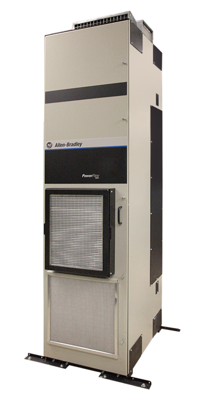
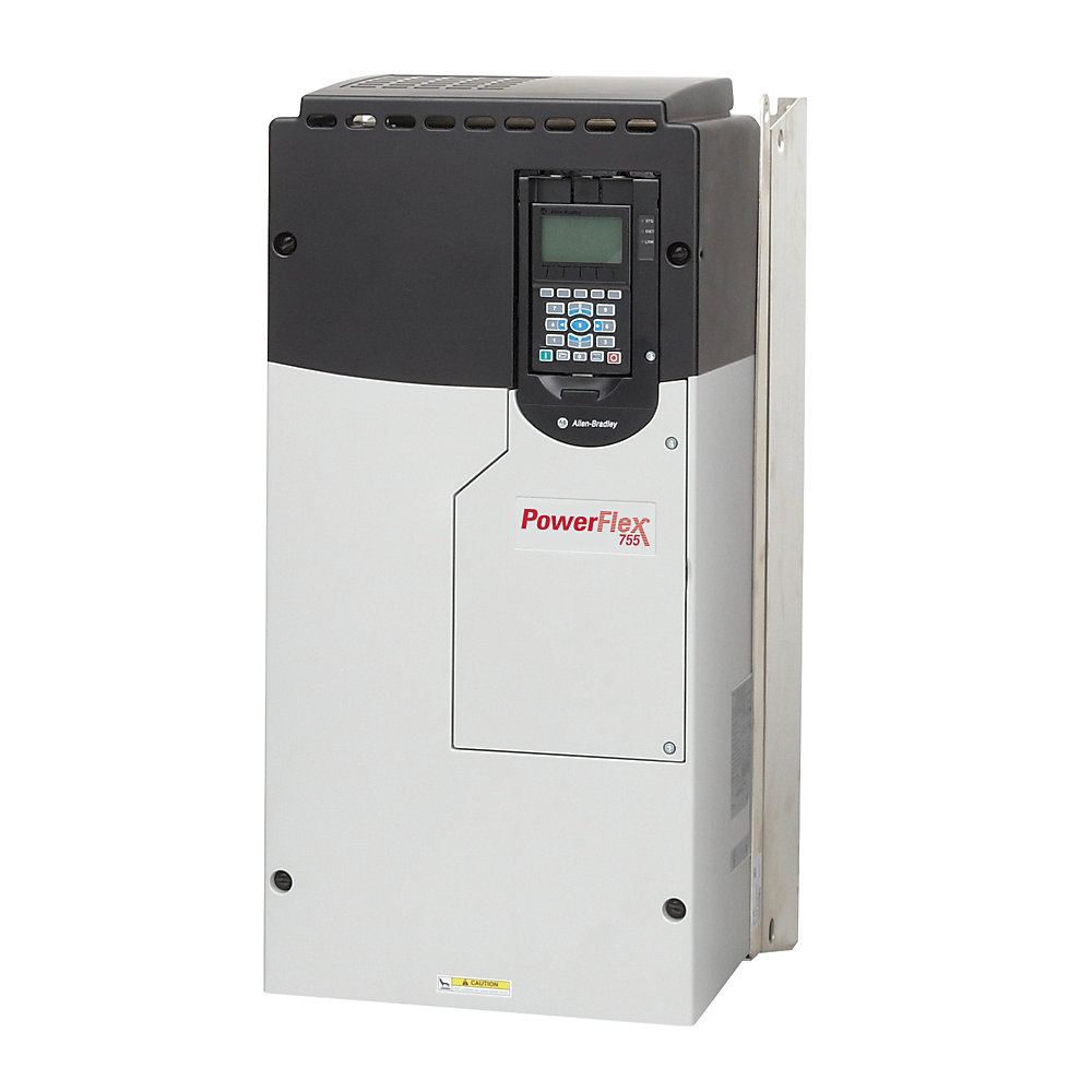
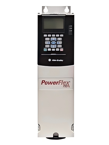
- Allen Bradley
- 20G1ALF330AN0NNNNN
- PowerFlex AC Drive
- USA
- 600 mm wide × 2450 mm high × 800 mm deep
- 100kg
- Xiamen, China
- New & In Stock
- T/T, PayPal, Western Union
- 1 Year
- 1-3 Working Days
- DHL, UPS, TNT, FedEx and EMS.
- 24-Hour Service
- COO
- 46
Our advantage

Global Logistics
We have a 10-year logistics and express cooperation agreement, so our products can be shipped to any place in the world.

Brand new and original
Our products are imported in bulk from the place of origin. Because of the cooperative relationship, our products are all original and 100% new.

24-hour service
We provide 7*24 hours service to our customers. We will be there whenever you need us.

Price advantage
All our products are priced very favorably because we have our own warehouse and supply.
| Company Information | |||
| [email protected] | |||
| Mobile | +8615980777398 | ||
| +8615980777398 | |||
| 15980777398 |
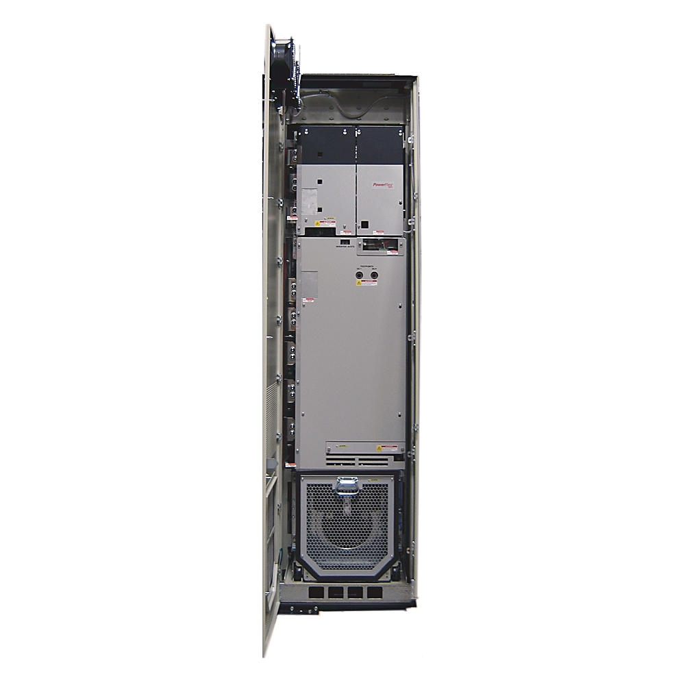
Allen-Bradley 20G1ALF330AN0NNNNN PowerFlex 755 AC Drive
1. Product Overview
The Allen-Bradley 20G1ALF330AN0NNNNN is a high-power PowerFlex 755 AC Drive designed for large three-phase industrial motor applications.
This configuration is rated for 690 VAC, with a continuous current rating of 330 A. It provides three different application-oriented power ratings: 355 kW Light Duty, 315 kW Normal Duty, and 250 kW Heavy Duty.
The drive uses forced-air cooling, an 800 mm deep MCC-style mechanical configuration, and a Type 1 / IP20 enclosure arrangement. It is equipped with embedded EtherNet/IP communication and uses an AC input with precharge and no external DC terminals.
The model is intended for demanding industrial installations where large motors require adjustable speed, controlled acceleration and deceleration, process regulation, motor protection, diagnostics, and integration with an industrial automation network.
2. Brand and Product Series
| Item | Specification |
|---|---|
| Brand | Allen-Bradley |
| Product Family | PowerFlex |
| Product Series | PowerFlex 755 |
| Product Type | AC Variable Frequency Drive |
| Model | 20G1ALF330AN0NNNNN |
| Configuration | PowerFlex 755 AC Drive |
| Voltage Class | 690 VAC |
| Rated Current | 330 A |
| Phase | Three Phase |
| Frame | Frame 8 |
| Cooling | Forced Air / Air Cooled |
| Communication | Embedded EtherNet/IP |
| Enclosure | Type 1 / IP20 |
| Mechanical Configuration | 800 mm Deep MCC Style |
| Input | AC Input with Precharge |
| External DC Terminals | None |
| Dynamic Braking | None |
| Filtering | Filtered |
| CM Jumper | Installed |
| HIM | Blank / No HIM |
The 20G1ALF330AN0NNNNN is a specific configuration within the PowerFlex 755 high-power drive range rather than a generic product number. The configuration identifies a 330 A, 690 VAC, Frame 8 drive with the stated enclosure, filtering, communication, and input characteristics.
3. Main Technical Parameters
| Parameter | Specification |
|---|---|
| Model | 20G1ALF330AN0NNNNN |
| Brand | Allen-Bradley |
| Series | PowerFlex 755 |
| Product Type | AC Variable Frequency Drive |
| Input Voltage | 690 VAC |
| Input Phase | 3 Phase |
| Rated Current | 330 A |
| Light-Duty Rating | 355 kW |
| Normal-Duty Rating | 315 kW |
| Heavy-Duty Rating | 250 kW |
| Frame Size | Frame 8 |
| Cooling Method | Forced Air |
| Input Configuration | AC Input with Precharge |
| External DC Terminals | None |
| Communication | Embedded EtherNet/IP |
| Protection Level | Standard Protection |
| Enclosure | Type 1 / IP20 |
| Mechanical Style | 800 mm Deep MCC Style |
| Filtering | Filtered |
| CM Jumper | Installed |
| Dynamic Braking | None |
| HIM | Blank / No HIM |
| Typical Installation | Industrial Indoor Installation |
| Main Function | Variable-Speed AC Motor Control |
| Typical Loads | Pumps, Fans, Blowers, Conveyors, Compressors, Mixers, Process Machinery |
| Depth | 800 mm configuration |
| Approximate Planning Width | Approximately 600 mm |
| Approximate Planning Height | Approximately 2450 mm |
| Approximate Planning Depth | Approximately 800 mm |
| Approximate Planning Weight | Approximately 100 kg class |
| Certified Dimensions | Verify from the applicable mechanical drawing |
| Certified Weight | Verify from the applicable mechanical/shipping documentation |
The electrical configuration is specified as 330 A, 355 kW LD, 315 kW ND, 250 kW HD, 690 VAC, three-phase, Frame 8, forced-air cooled, filtered, and with an installed CM jumper.
4. Product Configuration Explained
The model number 20G1ALF330AN0NNNNN identifies a particular combination of electrical and mechanical features.
The important characteristics are:
- PowerFlex 755 product family.
- 690 VAC voltage class.
- 330 A output-current class.
- Frame 8 construction.
- 355 kW Light-Duty capability.
- 315 kW Normal-Duty capability.
- 250 kW Heavy-Duty capability.
- Forced-air cooling.
- Embedded EtherNet/IP communication.
- AC input with precharge.
- No external DC terminals.
- Type 1 / IP20 enclosure configuration.
- 800 mm deep MCC-style construction.
- Filtered input configuration.
- CM jumper installed.
- No dynamic braking in the specified configuration.
- Blank configuration without a local HIM.
This combination makes the drive particularly suitable for large industrial motor systems where high voltage, high current capacity, network communication, and controlled motor operation are required.
5. Electrical Rating
The drive is designed for a 690 VAC three-phase power system.
At a rated current of 330 A, it is intended for large motor applications where a smaller drive would not provide sufficient current capacity.
The 690 VAC voltage class is particularly relevant to high-power industrial installations.
Large motors can operate at higher voltage levels so that the current required for a given amount of power remains within a manageable range.
The 330 A rating therefore provides a substantial motor-control capacity for large industrial machinery.
6. Power Ratings
The three main duty ratings of the model are:
| Duty Classification | Power Rating |
|---|---|
| Light Duty | 355 kW |
| Normal Duty | 315 kW |
| Heavy Duty | 250 kW |
These ratings should be considered according to the actual load profile.
A motor application with a relatively smooth variable-torque load may be evaluated using the Light-Duty rating.
A general industrial motor application with normal continuous loading can be evaluated against the Normal-Duty rating.
A machine requiring higher overload capability or greater starting torque may need to be evaluated using the Heavy-Duty rating.
The motor’s actual nameplate current and the mechanical load profile should always be considered in addition to the kW rating.
7. Light-Duty Rating – 355 kW
The 355 kW Light-Duty rating provides the highest stated continuous power level for this configuration.
Light-duty operation is generally associated with applications where the motor load does not continuously demand severe overload capability.
Typical examples include:
- Large centrifugal pumps.
- Large centrifugal fans.
- Cooling fans.
- Ventilation systems.
- Circulation pumps.
- Utility equipment.
- Variable-torque process equipment.
For these applications, the motor may operate at different speeds depending on the required flow, pressure, or airflow.
The drive allows the motor speed to be adjusted rather than requiring continuous full-speed operation.
8. Normal-Duty Rating – 315 kW
The 315 kW Normal-Duty rating is an important selection point for general industrial motor applications.
Normal-duty applications may include:
- Industrial pumps.
- Large blowers.
- Conveyors.
- Process fans.
- Material-handling equipment.
- Industrial machinery.
- Process equipment.
- General production systems.
For a 315 kW-class motor, the actual motor full-load current should be checked against the drive’s applicable current rating and duty classification.
The load’s acceleration requirements and overload profile should also be considered.
9. Heavy-Duty Rating – 250 kW
The 250 kW Heavy-Duty rating is intended for applications where the motor experiences more demanding operating conditions.
Examples can include:
- Heavy conveyors.
- High-inertia machinery.
- Mixers.
- Agitators.
- Material-handling systems.
- Certain compressors.
- Loaded mechanical equipment.
- Machines with frequent acceleration and deceleration.
Heavy-duty selection should be based on the actual motor current and required overload performance.
A 250 kW motor operating with high starting torque can impose a much greater demand on a drive than a 315 kW motor operating under a relatively stable variable-torque load.
10. Product Introduction
The PowerFlex 755 platform is designed for industrial variable-speed motor control.
The 20G1ALF330AN0NNNNN represents a high-power configuration within this platform.
It combines a 690 VAC input class with a 330 A current rating and a Frame 8 mechanical arrangement.
The drive can be used to control motor speed, acceleration, deceleration, direction, and other operating functions depending on the selected control architecture.
In a modern industrial system, the drive can also exchange information with the automation system through embedded EtherNet/IP.
This allows motor operation to become part of the overall machine or process-control strategy.
11. Embedded EtherNet/IP Communication
Embedded EtherNet/IP communication is one of the important features of this configuration.
The drive can be integrated into an industrial Ethernet control network.
Depending on the control system and application configuration, information exchanged with the drive can include:
- Start commands.
- Stop commands.
- Speed reference.
- Motor speed.
- Motor current.
- Output frequency.
- Drive status.
- Fault information.
- Warning information.
- Operating condition.
- Diagnostic information.
This type of communication is useful in large plants where many drives need to be monitored from a centralized control system.
It can also reduce the amount of individual hardwired control wiring required for operating commands and status information.
12. AC Input with Precharge
The 20G1ALF330AN0NNNNN uses an AC input with precharge.
The precharge function is important in high-power drives because the internal DC bus contains energy-storage components.
When the drive is energized, the precharge system manages the initial charging process of the DC bus.
The configuration also specifies no external DC terminals.
This makes the model appropriate for installations designed around an individual AC-input drive rather than a shared external DC-bus arrangement.
When replacing another drive, the DC-terminal configuration should be checked carefully.
13. Forced-Air Cooling
The drive uses a forced-air cooling system.
Large power semiconductor devices generate heat during operation.
The cooling system moves air through the drive to remove heat from the power components and maintain suitable operating temperatures.
For reliable operation, the installation should provide:
- Adequate airflow.
- Correct cabinet ventilation.
- Suitable ambient temperature.
- Clean cooling-air paths.
- Adequate service clearance.
- Proper maintenance access.
- Appropriate separation from other heat-producing equipment.
Dust accumulation and blocked ventilation paths can reduce cooling performance.
For this reason, ventilation should be included in the regular maintenance program.
14. Enclosure and Installation Configuration
The model is specified as Type 1 / IP20 with an 800 mm deep MCC-style mechanical configuration.
This configuration should be considered when designing:
- Electrical rooms.
- Motor-control centers.
- Drive cabinets.
- Industrial control rooms.
- Process-control systems.
- Large machinery electrical compartments.
The 800 mm depth is particularly important when determining cable-routing space and cabinet arrangement.
The installer should consider the complete mechanical envelope rather than only the drive body itself.
15. Dimensions and Weight
The user-requested specification includes dimensions and weight in kilograms.
Because exact mechanical dimensions and shipping weight can depend on the detailed product configuration and mechanical documentation, the values below are provided as preliminary planning values, not certified fabrication or lifting data.
| Mechanical Parameter | Specification |
|---|---|
| Model | 20G1ALF330AN0NNNNN |
| Mechanical Style | 800 mm Deep MCC Style |
| Nominal Configuration Depth | 800 mm |
| Approximate Width for Planning | 600 mm |
| Approximate Height for Planning | 2450 mm |
| Approximate Depth for Planning | 800 mm |
| Approximate Weight for Planning | Approximately 100 kg |
| Exact Shipping Weight | Verify from product-specific documentation |
| Exact Overall Dimensions | Verify from the applicable mechanical drawing |
| Lifting Calculation | Use certified equipment weight |
| Cabinet Fabrication | Use certified mechanical dimensions |
The 800 mm depth is part of the specified configuration.
The approximate 600 mm × 2450 mm × 800 mm envelope is suitable only for preliminary layout discussion.
For equipment transportation, crane selection, lifting, floor loading, cabinet fabrication, and installation clearance, the exact mechanical drawing and shipping data should be used.
16. Pump Applications
The drive is suitable for large pump systems where variable-speed control is required.
Potential applications include:
- Water-treatment pumps.
- Cooling-water pumps.
- Process-water pumps.
- Circulation pumps.
- Industrial transfer pumps.
- Utility pumps.
- Cooling-system pumps.
- Large process pumps.
A pump driven directly from the utility supply normally operates at a fixed speed determined by supply frequency and motor characteristics.
With a variable-frequency drive, the pump motor can operate at different speeds.
This allows the process-control system to adjust pump output according to actual demand.
17. Fan Applications
Large industrial fans and blowers are another important application area.
Examples include:
- Furnace fans.
- Exhaust fans.
- Combustion-air fans.
- Cooling fans.
- Ventilation fans.
- Dust-collection blowers.
- Process-air blowers.
- Industrial ventilation equipment.
Fan speed can be adjusted according to airflow requirements.
This can provide more flexible process control than operating the motor continuously at full speed.
18. Conveyor Applications
The 330 A configuration is suitable for large conveyor systems when the motor and load requirements fall within the applicable drive rating.
Potential applications include:
- Bulk-material conveyors.
- Mining conveyors.
- Production conveyors.
- Heavy material-handling conveyors.
- Transfer conveyors.
- Long-distance conveyor systems.
Controlled acceleration can reduce sudden torque transmission to the conveyor belt, gearbox, coupling, and drive shaft.
Controlled deceleration can also help reduce mechanical shock during stopping.
19. Compressor Applications
Large compressors can require substantial motor current and controlled acceleration.
Possible applications include:
- Industrial air compressors.
- Process compressors.
- Gas-related equipment.
- Utility compressors.
- Cooling-system compressors.
The drive can provide variable motor speed where the compressor design allows it.
Compressor selection should take into account the compressor type, required starting torque, operating range, minimum speed, maximum speed, and motor cooling.
20. Mixer and Agitator Applications
Large mixers and agitators can have significant starting torque requirements.
Potential applications include:
- Chemical mixing.
- Industrial blending.
- Process tanks.
- Slurry systems.
- Material processing.
- Batch production.
- Large agitators.
For mixers, the drive should be selected according to the actual mechanical torque curve.
Viscosity, material density, tank geometry, impeller size, starting condition, and operating speed can all affect the required drive capacity.
21. Process Machinery Applications
The drive can be used in process machinery where motor speed is an important part of the production process.
Typical applications include:
- Manufacturing equipment.
- Material-processing equipment.
- Production lines.
- Industrial handling machinery.
- Process pumps.
- Process fans.
- Large rotating machinery.
Variable-speed control can allow the process to operate at different production rates without changing the basic motor and mechanical system.
22. Main Product Advantages
22.1 High Current Capacity
The 330 A rating provides a substantial output capacity for large industrial motors.
This makes the drive suitable for applications beyond the range of many smaller industrial VFDs.
22.2 690 VAC High-Power Operation
The 690 VAC voltage class is suitable for high-power industrial motor systems.
It is commonly associated with large motor installations where higher voltage helps keep current within a practical range.
22.3 Three Duty Ratings
The drive provides:
- 355 kW Light Duty.
- 315 kW Normal Duty.
- 250 kW Heavy Duty.
This gives engineers a way to evaluate the same drive family against different types of load conditions.
22.4 Embedded EtherNet/IP
The embedded communication capability simplifies integration with an industrial automation network.
The drive can provide operating data and receive commands through the network.
22.5 Controlled Acceleration
The drive can accelerate the motor in a controlled manner.
This can reduce sudden mechanical shock compared with direct full-voltage motor starting.
22.6 Controlled Deceleration
Controlled stopping can help reduce mechanical shock in conveyors, fans, pumps, and other rotating machinery.
22.7 Adjustable Motor Speed
The motor can operate at different speeds according to process requirements.
This is particularly useful in pump and fan applications.
22.8 Reduced Mechanical Stress
Controlled motor operation can reduce sudden torque changes affecting:
- Shafts.
- Couplings.
- Gearboxes.
- Belts.
- Chains.
- Bearings.
- Conveyor structures.
- Pump components.
- Fan assemblies.
23. Energy Management
Variable-speed operation can improve energy utilization in applications where the required mechanical output changes over time.
This is particularly relevant to centrifugal pumps and fans.
For example, a pump may not require maximum flow during every stage of a production process.
Instead of continuously operating the motor at full speed, the drive can reduce motor speed when process demand decreases.
The actual energy benefit depends on the mechanical load, operating schedule, system design, motor efficiency, process requirements, and control strategy.
24. Motor Control
The drive can be integrated into motor-control systems requiring:
- Speed control.
- Start and stop control.
- Acceleration control.
- Deceleration control.
- Direction control where applicable.
- Process-based speed reference.
- Network-based commands.
- Drive status monitoring.
- Fault monitoring.
- Diagnostic information.
These capabilities make the drive suitable for centralized industrial control systems.
25. Maintenance Considerations
Large high-power drives require regular maintenance.
Recommended inspection areas include:
| Maintenance Item | Inspection |
|---|---|
| Cooling Fans | Check operation and unusual noise |
| Airflow | Confirm unobstructed cooling path |
| Ventilation | Check cabinet airflow |
| Power Connections | Inspect for looseness or overheating |
| Motor Cables | Check connections and insulation condition |
| Grounding | Verify grounding system |
| Network Cable | Check communication connection |
| Drive Faults | Review fault history |
| Drive Warnings | Review recurring warnings |
| Cabinet | Check dust and contamination |
| Temperature | Check abnormal heating |
| Mechanical Mounting | Verify secure installation |
| Control Wiring | Check terminals and connections |
Regular inspection can help identify developing problems before they result in an unexpected shutdown.
26. Installation Environment
The drive should be installed in an environment suitable for industrial electronic equipment.
Important considerations include:
- Ambient temperature.
- Humidity.
- Altitude.
- Dust.
- Corrosive gases.
- Conductive contamination.
- Vibration.
- Cabinet ventilation.
- Direct heat sources.
- Service accessibility.
The installation environment should be evaluated before final equipment selection.
For outdoor or harsh environments, an appropriate enclosure or cabinet arrangement may be required.
27. Motor Selection
The motor should not be selected only by matching its kW rating to the drive’s kW rating.
The following parameters should also be checked:
| Motor Parameter | Why It Matters |
|---|---|
| Rated Voltage | Must be compatible with the drive output system |
| Rated Current | Determines drive current requirement |
| Rated Power | Establishes basic capacity |
| Rated Frequency | Required for correct motor operation |
| Rated Speed | Important for operating range |
| Starting Torque | Important for acceleration |
| Load Torque | Determines actual drive demand |
| Inertia | Affects acceleration and deceleration |
| Cooling | Important at low speed |
| Insulation | Important for VFD operation |
| Cable Length | Can affect motor-drive installation |
| Operating Speed | Determines control range |
| Overload Requirement | Determines duty selection |
28. Recommended Same-Series or Related Models
The following five models are closely related PowerFlex 755 configurations and are useful for comparison with the requested 330 A model.
| Model | Voltage | Current | Light Duty | Normal Duty | Heavy Duty | Frame |
|---|---|---|---|---|---|---|
| 20G1ALF265AN0NNNNN | 690 VAC | 265 A | 315 kW | 250 kW | 200 kW | 8 |
| 20G1ALF370AN0NNNNN | 690 VAC | 370 A | 400 kW | 355 kW | 300 kW | 8 |
| 20G1ALF415AN0NNNNN | 690 VAC | 415 A | 450 kW | 400 kW | 355 kW | 8 |
| 20G1ALF460AN0NNNNN | 690 VAC | 460 A | 500 kW | 450 kW | 375 kW | 8 |
| 20G1ALF500AN0NNNNN | 690 VAC | 500 A | 530 kW | 500 kW | 400 kW | 8 |
These models form a closely related high-power 690 VAC range, with increasing current and power capacity.
29. Related Model – 20G1ALF265AN0NNNNN
The 20G1ALF265AN0NNNNN is a lower-current member of the same 690 VAC configuration family.
| Parameter | Specification |
|---|---|
| Model | 20G1ALF265AN0NNNNN |
| Voltage | 690 VAC |
| Current | 265 A |
| Light Duty | 315 kW |
| Normal Duty | 250 kW |
| Heavy Duty | 200 kW |
| Frame | 8 |
| Cooling | Air cooled |
| Input | AC input with precharge |
| DC Terminals | None |
| Communication | Embedded EtherNet/IP |
| Enclosure | Type 1 / IP20 |
| Mechanical Style | 800 mm Deep MCC Style |
| Approximate Planning Dimensions | 600 W × 2450 H × 800 D mm |
| Approximate Planning Weight | Approximately 100 kg class |
This model can be considered where the motor current requirement is below the 330 A configuration.
30. Related Model – 20G1ALF370AN0NNNNN
The 20G1ALF370AN0NNNNN provides a higher current capacity than the requested model.
| Parameter | Specification |
|---|---|
| Model | 20G1ALF370AN0NNNNN |
| Voltage | 690 VAC |
| Current | 370 A |
| Light Duty | 400 kW |
| Normal Duty | 355 kW |
| Heavy Duty | 300 kW |
| Frame | 8 |
| Cooling | Air cooled |
| Input | AC input with precharge |
| DC Terminals | None |
| Communication | Embedded EtherNet/IP |
| Enclosure | Type 1 / IP20 |
| Mechanical Style | 800 mm Deep MCC Style |
| Approximate Planning Dimensions | 600 W × 2450 H × 800 D mm |
| Approximate Planning Weight | Approximately 100 kg class |
This model is appropriate for applications requiring more current capacity than the 330 A configuration.
31. Related Model – 20G1ALF415AN0NNNNN
The 20G1ALF415AN0NNNNN provides 415 A output capacity.
| Parameter | Specification |
|---|---|
| Model | 20G1ALF415AN0NNNNN |
| Voltage | 690 VAC |
| Current | 415 A |
| Light Duty | 450 kW |
| Normal Duty | 400 kW |
| Heavy Duty | 355 kW |
| Frame | 8 |
| Cooling | Air cooled |
| Input | AC input with precharge |
| DC Terminals | None |
| Communication | Embedded EtherNet/IP |
| Enclosure | Type 1 / IP20 |
| Mechanical Style | 800 mm Deep MCC Style |
| Approximate Planning Dimensions | 600 W × 2450 H × 800 D mm |
| Approximate Planning Weight | Approximately 100 kg class |
This configuration is intended for still larger motor systems within the same high-power voltage class.
32. Related Model – 20G1ALF460AN0NNNNN
The 20G1ALF460AN0NNNNN is rated at 460 A.
| Parameter | Specification |
|---|---|
| Model | 20G1ALF460AN0NNNNN |
| Voltage | 690 VAC |
| Current | 460 A |
| Light Duty | 500 kW |
| Normal Duty | 450 kW |
| Heavy Duty | 375 kW |
| Frame | 8 |
| Cooling | Air cooled |
| Input | AC input with precharge |
| DC Terminals | None |
| Communication | Embedded EtherNet/IP |
| Enclosure | Type 1 / IP20 |
| Mechanical Style | 800 mm Deep MCC Style |
| Approximate Planning Dimensions | 600 W × 2450 H × 800 D mm |
| Approximate Planning Weight | Approximately 100 kg class |
It is suitable for applications requiring substantially more current capacity than the 330 A model.
33. Related Model – 20G1ALF500AN0NNNNN
The 20G1ALF500AN0NNNNN is rated at 500 A and represents a higher-capacity configuration in the same 690 VAC family.
| Parameter | Specification |
|---|---|
| Model | 20G1ALF500AN0NNNNN |
| Voltage | 690 VAC |
| Current | 500 A |
| Light Duty | 530 kW |
| Normal Duty | 500 kW |
| Heavy Duty | 400 kW |
| Frame | 8 |
| Cooling | Air cooled |
| Input | AC input with precharge |
| DC Terminals | None |
| Communication | Embedded EtherNet/IP |
| Enclosure | Type 1 / IP20 |
| Mechanical Style | 800 mm Deep MCC Style |
| Approximate Planning Dimensions | 600 W × 2450 H × 800 D mm |
| Approximate Planning Weight | Approximately 100 kg class |
The 500 A configuration is intended for larger motor applications where a higher current rating is required.
34. Five Same-Brand Reference Models
The following models can be used as same-brand reference products for comparison.
They cover different current levels, voltage classes, and configurations within the broader PowerFlex product range.
| Model | Series / Family | Voltage Class | Current | Power Reference | Frame / Configuration |
|---|---|---|---|---|---|
| 20G1ANF061JN0NNNNN | PowerFlex 755 | 690 VAC | 61 A | 55 kW ND / 45 kW HD | Frame 6 |
| 20G1ANF082JN0NNNNN | PowerFlex 755 | 690 VAC | 82 A | 75 kW ND / 55 kW HD | Frame 6 |
| 20G1ANF098JN0NNNNN | PowerFlex 755 | 690 VAC | 98 A | 90 kW ND / 75 kW HD | Frame 6 |
| 20G1ANF142JN0NNNNN | PowerFlex 755 | 690 VAC | 142 A | 132 kW ND / 110 kW HD | Frame 7 |
| 20G1ANE099JN0NNNNN | PowerFlex 755 | 600 VAC | 99 A | 100 HP ND / 75 HP HD | Frame 6 |
These models illustrate smaller current capacities and, in the case of the 600 VAC version, a different voltage class.
35. Same-Brand Reference Model Parameters
| Model | Voltage | Current | Normal Duty | Heavy Duty | Cooling | Communication |
|---|---|---|---|---|---|---|
| 20G1ANF061JN0NNNNN | 690 VAC | 61 A | 55 kW | 45 kW | Air cooled | Embedded EtherNet/IP |
| 20G1ANF082JN0NNNNN | 690 VAC | 82 A | 75 kW | 55 kW | Air cooled | Embedded EtherNet/IP |
| 20G1ANF098JN0NNNNN | 690 VAC | 98 A | 90 kW | 75 kW | Air cooled | Embedded EtherNet/IP |
| 20G1ANF142JN0NNNNN | 690 VAC | 142 A | 132 kW | 110 kW | Air cooled | Embedded EtherNet/IP |
| 20G1ANE099JN0NNNNN | 600 VAC | 99 A | 100 HP | 75 HP | Air cooled | Embedded EtherNet/IP |
36. Model Capacity Comparison
| Model | Current | Light Duty | Normal Duty | Heavy Duty |
|---|---|---|---|---|
| 20G1ALF265AN0NNNNN | 265 A | 315 kW | 250 kW | 200 kW |
| 20G1ALF330AN0NNNNN | 330 A | 355 kW | 315 kW | 250 kW |
| 20G1ALF370AN0NNNNN | 370 A | 400 kW | 355 kW | 300 kW |
| 20G1ALF415AN0NNNNN | 415 A | 450 kW | 400 kW | 355 kW |
| 20G1ALF460AN0NNNNN | 460 A | 500 kW | 450 kW | 375 kW |
| 20G1ALF500AN0NNNNN | 500 A | 530 kW | 500 kW | 400 kW |
The 330 A model sits between the 265 A and 370 A configurations in this group.
For a replacement or new installation, the correct model should be selected from the motor current and actual load requirements rather than simply moving to the next larger model.
37. Application Selection
| Application | Suitability | Important Selection Point |
|---|---|---|
| Large Centrifugal Pump | High | Check motor current and pump operating range |
| Large Fan | High | Check variable-torque load profile |
| Industrial Blower | High | Check continuous operating current |
| Conveyor | High | Check starting torque and inertia |
| Compressor | High | Check compressor torque curve |
| Mixer | High | Check starting torque |
| Agitator | High | Check viscosity and load inertia |
| Process Machinery | High | Check overload requirements |
| Material Handling | High | Check acceleration and mechanical loading |
| Utility Equipment | High | Check duty classification |
38. Advantages in Pump Systems
For large pump systems, the drive provides several practical control benefits.
The motor can be accelerated gradually rather than being connected directly to the full operating condition.
Pump speed can also be adjusted according to process demand.
This can be useful for:
- Pressure control.
- Flow control.
- Cooling-water circulation.
- Process-water regulation.
- Transfer systems.
- Water-treatment processes.
39. Advantages in Fan Systems
For large fans and blowers, variable-speed operation allows the airflow to follow the process requirement.
Potential benefits include:
- Adjustable airflow.
- Controlled starting.
- Controlled stopping.
- Reduced mechanical shock.
- Flexible production control.
- Network monitoring.
- Process synchronization.
40. Advantages in Conveyor Systems
For conveyors, the drive can help provide controlled movement of material.
Potential benefits include:
- Smooth acceleration.
- Smooth deceleration.
- Adjustable conveyor speed.
- Reduced belt shock.
- Reduced mechanical stress.
- Better process coordination.
- Network-based monitoring.
For very long or heavily loaded conveyors, the complete mechanical system should be evaluated for starting torque and acceleration time.
41. Advantages in Process Machinery
Process machinery often requires different operating speeds at different stages of production.
The drive can allow one motor to operate at multiple controlled speeds.
This can be useful for:
- Production-rate adjustment.
- Batch processing.
- Material handling.
- Mixing.
- Pumping.
- Ventilation.
- Process synchronization.
42. Advantages in High-Inertia Equipment
High-inertia equipment can place considerable demand on a motor during acceleration.
Examples include:
- Large fans.
- Large blowers.
- Heavy conveyors.
- Centrifugal equipment.
- Large rotating machinery.
The drive can control the acceleration profile so that the motor does not have to change speed instantaneously.
This can help reduce mechanical stress and improve process stability.
43. Electrical System Advantages
The 690 VAC, 330 A configuration is suitable for large motor installations.
The high-voltage motor system can provide substantial power transfer while keeping current within a practical range for large industrial installations.
The AC-input configuration with precharge provides a defined electrical arrangement for individual drive applications.
44. Control System Advantages
The embedded EtherNet/IP capability makes the drive suitable for centralized automation.
A control system can monitor drive conditions and issue operating commands through the industrial network.
This can simplify:
- Centralized control.
- Drive monitoring.
- Fault diagnostics.
- Production coordination.
- Process control.
- Maintenance troubleshooting.
45. Mechanical Advantages
Variable-speed motor control can reduce sudden changes in torque.
This can help reduce stress on:
- Gearboxes.
- Couplings.
- Shafts.
- Belts.
- Chains.
- Bearings.
- Pump assemblies.
- Fan assemblies.
- Conveyor systems.
The actual mechanical benefit depends on correct drive configuration and application-specific acceleration and deceleration settings.
46. Replacement Selection
When using the 20G1ALF330AN0NNNNN as a replacement, do not compare only the kW rating.
The following should be checked:
| Item | Required Verification |
|---|---|
| Supply Voltage | 690 VAC |
| Motor Voltage | Compatible with drive output |
| Motor Current | Within applicable drive rating |
| Motor Power | Within applicable duty rating |
| Duty | LD / ND / HD |
| Overload | Match actual application |
| Input Arrangement | AC input with precharge |
| DC Terminals | Confirm external DC bus is not required |
| Communication | Confirm EtherNet/IP requirements |
| Enclosure | Type 1 / IP20 |
| Cabinet Depth | 800 mm configuration |
| Cooling | Forced air |
| Braking | Confirm dynamic braking requirement |
| HIM | Confirm local operator-interface requirement |
| Dimensions | Confirm exact mechanical drawing |
| Weight | Confirm certified equipment weight |
47. Detailed Specification Summary
| Parameter | 20G1ALF330AN0NNNNN |
|---|---|
| Brand | Allen-Bradley |
| Series | PowerFlex 755 |
| Product | PowerFlex 755 AC Drive |
| Model | 20G1ALF330AN0NNNNN |
| Voltage | 690 VAC |
| Phase | 3 Phase |
| Rated Current | 330 A |
| Light Duty | 355 kW |
| Normal Duty | 315 kW |
| Heavy Duty | 250 kW |
| Frame | 8 |
| Cooling | Forced Air |
| Input | AC Input with Precharge |
| External DC Terminals | None |
| Communication | Embedded EtherNet/IP |
| Protection | Standard Protection |
| Enclosure | Type 1 / IP20 |
| Mechanical Style | 800 mm Deep MCC Style |
| Filtering | Filtered |
| CM Jumper | Installed |
| Dynamic Braking | None |
| HIM | Blank / No HIM |
| Approx. Width | 600 mm planning value |
| Approx. Height | 2450 mm planning value |
| Approx. Depth | 800 mm |
| Approx. Weight | Approximately 100 kg planning value |
| Exact Weight | Confirm from product-specific mechanical documentation |
| Exact Dimensions | Confirm from product-specific mechanical documentation |
| Main Applications | Pumps, fans, blowers, conveyors, compressors, mixers, process machinery |
| Installation | Industrial application |
48. Final Technical Description
The Allen-Bradley 20G1ALF330AN0NNNNN PowerFlex 755 AC Drive is a high-power industrial variable-frequency drive designed for large three-phase motor applications.
The unit is rated at 690 VAC and 330 A, with stated power ratings of 355 kW Light Duty, 315 kW Normal Duty, and 250 kW Heavy Duty.
It uses a Frame 8, forced-air-cooled construction and an 800 mm deep MCC-style mechanical configuration.
The drive includes embedded EtherNet/IP communication, allowing it to be integrated into a networked industrial control system.
The specified configuration uses an AC input with precharge, has no external DC terminals, uses a filtered input configuration with CM jumper installed, and does not include dynamic braking or a local HIM in the stated configuration.
The drive is well suited to large pumps, fans, blowers, conveyors, compressors, mixers, material-handling systems, and process machinery.
Its principal advantages are its high current capacity, 690 VAC voltage class, multiple duty ratings, network communication, adjustable motor speed, controlled acceleration and deceleration, and suitability for large industrial motor systems.
For preliminary equipment planning, an approximately 600 mm wide × 2450 mm high × 800 mm deep envelope and approximately 100 kg planning weight can be used cautiously.
However, those mechanical figures should not be used as certified installation, shipping, lifting, or cabinet-fabrication data. The exact mechanical drawing and equipment documentation should be used for final engineering work.
The closely related 690 VAC models include the 265 A, 370 A, 415 A, 460 A, and 500 A configurations, providing a range of current and power capacities around the 330 A model.
For final selection, the most important factors remain motor current, motor voltage, duty classification, overload requirement, starting torque, load inertia, operating speed, environmental conditions, cabinet arrangement, braking requirements, and control-system requirements.