
NewsNEWCENTER
Featured products
Contact Us
Allen Bradley 1606-XLP100E Power Supply Installation Guide
2026-09-15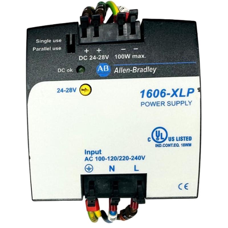
Table of Contents
- Allen Bradley 1606-XLP100E Power Supply Installation Overview
- Allen Bradley 1606-XLP100E Power Supply Function in Control Systems
- Allen Bradley 1606-XLP100E Installation Preparation
- Allen Bradley 1606-XLP100E Mounting and Cabinet Layout
- Allen Bradley 1606-XLP100E Wiring and Electrical Setup
- Allen Bradley 1606-XLP100E Setup and Commissioning
- Allen Bradley 1606-XLP100E Installation Validation
- Allen Bradley 1606-XLP100E Field Commissioning Case
- Allen Bradley 1606-XLP100E Installation FAQ
- Allen Bradley 1606-XLP100E Technical Summary
Allen Bradley 1606-XLP100E Power Supply Installation Overview
Allen Bradley 1606-XLP100E Power Supply installation should be approached as a complete industrial DC power distribution task. The key concerns are not limited to mounting the unit; engineers must also verify the incoming supply, protective earth, output polarity, connected load, conductor sizing, cabinet ventilation and downstream voltage. A structured Installation Guide helps establish a stable power source for PLC Controllers, I/O Modules, HMIs, Sensors and other automation equipment.
The 1606-XLP100E is part of the Allen Bradley 1606 family of industrial power supplies. In a properly designed control cabinet, it provides the DC power required by low-voltage control equipment and becomes an important reference point during later Setup, Commissioning and Fault Diagnosis.
Allen Bradley 1606-XLP100E Power Supply Function in Control Systems
The power supply sits between the cabinet’s incoming electrical distribution and the DC-powered automation devices. Its role is to provide a stable DC source while the machine changes operating states and connected loads vary.
- PLC Controller power
- Remote I/O Modules
- HMI and operator interfaces
- Industrial network equipment
- Control relays and interface circuits
- Instrumentation and Sensors
- Other DC-powered control devices
Because several devices may share the same DC bus, a fault anywhere in the distribution path can appear to be a power supply problem. Installation engineers should therefore document source and load measurements during commissioning.
Allen Bradley 1606-XLP100E Installation Preparation
Before mounting the Allen Bradley 1606-XLP100E, inspect the electrical design and calculate the expected DC load. The calculation should include normal operating current as well as temporary load changes caused by relays, solenoids, contactors and other inductive devices.
- Review the control-panel electrical drawings.
- Confirm the incoming power arrangement.
- Calculate the total connected DC load.
- Review branch circuit protection.
- Verify protective earth continuity.
- Check cabinet temperature and airflow.
- Prepare suitable input and output conductors.
- Plan clear separation between power and sensitive signal wiring.
Before any electrical connection is made, follow the site’s approved isolation and lockout procedures. Hazardous-voltage work should only be performed by appropriately qualified personnel.
Allen Bradley 1606-XLP100E Mounting and Cabinet Layout
Install the Allen Bradley 1606-XLP100E securely in the designated cabinet location. If the installation uses DIN-rail mounting, inspect the rail for mechanical damage and verify that the power supply is fully seated.
Cabinet positioning should provide adequate airflow and convenient access for maintenance. Avoid placing the power supply directly next to equipment that produces significant heat, such as high-power drives or braking components.
Good cabinet layout also reduces the possibility of electrical interference. High-current motor conductors and switching circuits should be routed appropriately away from sensitive control and communication wiring.
Allen Bradley 1606-XLP100E Wiring and Electrical Setup
Before wiring, identify the actual input and output terminals on the specific 1606-XLP100E unit and compare them with the approved electrical drawing. Do not assume that terminal arrangements are identical across every Allen Bradley 1606-series model.
- Verify the incoming AC conductors.
- Connect protective earth correctly.
- Confirm the DC output terminals.
- Check output polarity.
- Select conductors according to the actual installation load.
- Secure all terminals correctly.
- Label outgoing DC circuits.
- Inspect the completed wiring before energization.
Incoming Power
      |
      v
Allen Bradley 1606-XLP100E
      |
      v
     DC Bus
      |
 +----+-----+---------+
 |          |         |
PLC       Remote      HMI
 |         I/O
 |          |
 +----------+------+
            |
         Sensors
Pay particular attention to the DC distribution terminals. A high-resistance connection may pass a basic continuity test while still causing a significant voltage drop when the machine is operating at higher load.
Allen Bradley 1606-XLP100E Setup and Commissioning
Commissioning should be performed progressively so that abnormal electrical behavior can be isolated quickly.
- Complete the final wiring inspection.
- Verify incoming supply conditions.
- Energize the power supply using the approved startup procedure.
- Measure the DC output before connecting the complete load.
- Power the PLC Controller.
- Enable remote I/O and communication equipment.
- Activate field devices progressively.
- Run the machine under representative production conditions.
During Setup, compare the DC output under idle and loaded conditions. If the source remains stable while remote equipment experiences voltage loss, the next troubleshooting target should be the distribution network.
Allen Bradley 1606-XLP100E Installation Validation
A completed Installation should be validated at both the power source and the connected equipment.
- Stable DC output at the power supply.
- Normal PLC Controller startup.
- Stable remote I/O operation.
- Reliable industrial communication.
- Normal HMI operation.
- Consistent Sensor signals.
- No unexplained control-system resets.
- No excessive cabinet heating.
Record commissioning measurements together with the operating conditions under which they were taken. These records become useful reference data when the system requires future Troubleshooting or maintenance.
Allen Bradley 1606-XLP100E Field Commissioning Case
During commissioning of a material-handling machine, the control system operated normally during initial testing but the PLC Controller restarted when several field devices were activated simultaneously.
The Allen Bradley 1606-XLP100E was initially considered a possible source of the problem. Engineers measured approximately 24.1 VDC at the power supply while the machine was idle. The reading was stable.
They then measured the remote I/O cabinet during simultaneous load activation. The remote voltage temporarily decreased to approximately 22.5 VDC while the power supply output remained close to 24 VDC.
The engineering team inspected the DC distribution path and discovered a loose terminal connection in the cabinet’s distribution block. After correcting the connection and checking the remaining terminals, the remote voltage remained close to 24 VDC during repeated operating cycles.
The power supply did not require replacement. The case demonstrates why a complete Installation and Commissioning process should establish voltage measurements at both the source and the actual loads.
Allen Bradley 1606-XLP100E Installation FAQ
What should be checked before installing the Allen Bradley 1606-XLP100E?
Verify the electrical drawings, incoming power, connected DC load, grounding, cabinet environment, protective devices and conductor sizing.
Why is output polarity verification necessary?
Incorrect polarity can damage connected electronic equipment. Always confirm the actual terminal markings before connecting downstream devices.
Should voltage be measured at remote I/O equipment?
Yes. Source voltage may remain stable while cable resistance, loose terminals or overloaded branches create voltage loss at remote loads.
Why should commissioning values be recorded?
Baseline measurements make future Troubleshooting faster because technicians can compare current readings with the original operating condition.
Allen Bradley 1606-XLP100E Technical Summary
The Allen Bradley 1606-XLP100E Power Supply Installation Guide should cover the complete DC power path, including preparation, cabinet mounting, electrical wiring, Setup, Commissioning and final validation. A measurement-based installation approach provides a reliable foundation for PLC Controllers, I/O Modules, HMIs and Sensors while creating useful baseline information for future Fault Diagnosis.