

ProductPRODUCT
Featured products








Contact Us
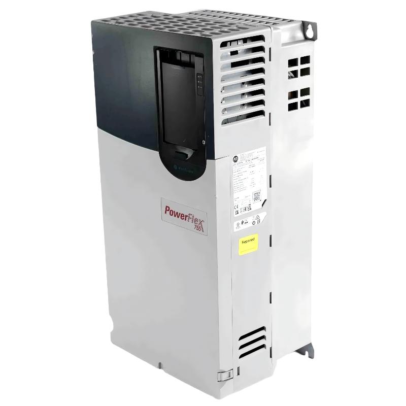
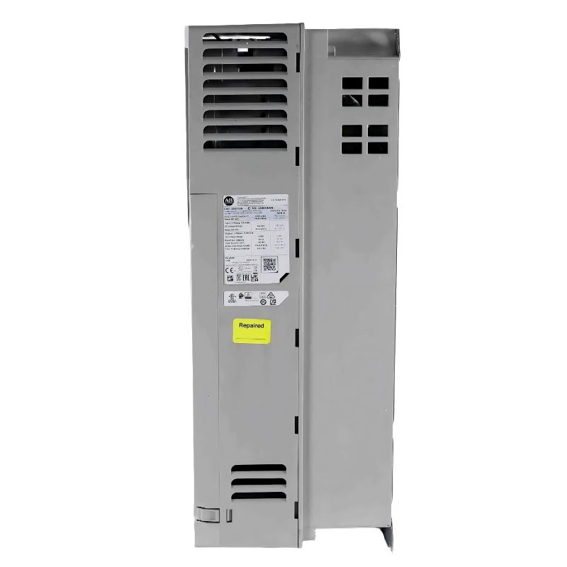
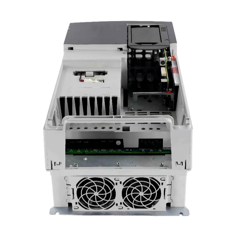
- Allen Bradley
- 20G14TC540JN0NNNNN
- PowerFlex AC Drive
- USA
- 2145 × 778 × 421 mm
- 162kg
- Xiamen, China
- New & In Stock
- T/T, PayPal, Western Union
- 1 Year
- 1-3 Working Days
- DHL, UPS, TNT, FedEx and EMS.
- 24-Hour Service
- COO
- 40
Our advantage

Global Logistics
We have a 10-year logistics and express cooperation agreement, so our products can be shipped to any place in the world.

Brand new and original
Our products are imported in bulk from the place of origin. Because of the cooperative relationship, our products are all original and 100% new.

24-hour service
We provide 7*24 hours service to our customers. We will be there whenever you need us.

Price advantage
All our products are priced very favorably because we have our own warehouse and supply.
| Company Information | |||
| [email protected] | |||
| Mobile | +8615980777398 | ||
| +8615980777398 | |||
| 15980777398 |
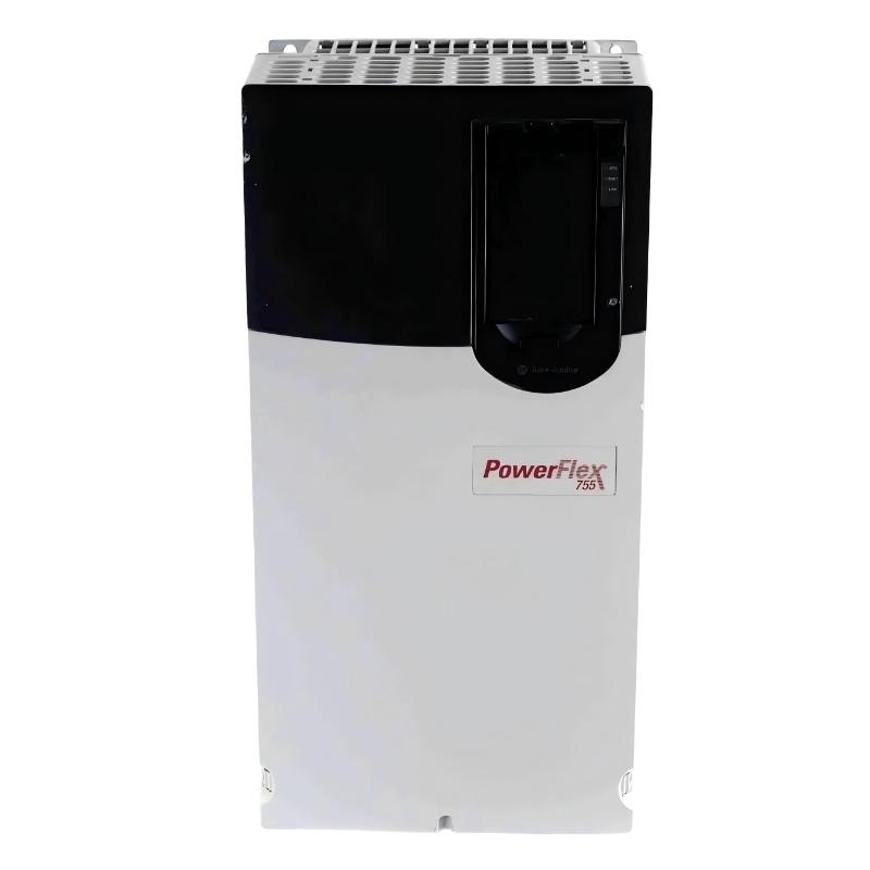
Allen-Bradley 20G14TC540JN0NNNNN PowerFlex 755 AC Drive – Complete Technical Specifications, Applications, Advantages and Related Models
1. Product Overview
The Allen-Bradley 20G14TC540JN0NNNNN is a high-power PowerFlex 755 Air-Cooled AC Drive designed for large industrial motor-control applications.
It is a 400 VAC, three-phase PowerFlex 755 drive with a DC input and precharge configuration. The drive is designed for high-current applications and provides a 540 A Normal Duty rating, with approximately 315 kW Normal Duty power capability.
The model is built on the large Frame 8 platform and uses forced-air cooling. Its open-type construction means that it is normally integrated into an appropriately engineered industrial cabinet, MCC section, control enclosure, or other protected electrical installation.
The 20G14TC540JN0NNNNN is particularly relevant to applications involving large motors, large pumps, industrial fans, conveyors, process machinery, mining equipment, material-handling systems, and common-DC-bus installations.
The TC configuration is especially important because this family is designed around a DC-input/common-bus architecture. This makes the drive different from a conventional standalone AC-input variable-frequency drive.
The catalog number is:
20G14TC540JN0NNNNN
This is a substantial industrial drive intended for engineered systems rather than compact machine applications.
2. Brand and Product Series
| Parameter | Specification |
|---|---|
| Brand | Allen-Bradley |
| Product Family | PowerFlex |
| Product Series | PowerFlex 755 |
| Product Sub-Series | PowerFlex 755 AC Drive |
| Product Type | Air-Cooled AC Drive |
| Catalog Number | 20G14TC540JN0NNNNN |
| Power Architecture | PowerFlex 750-Series |
| Voltage Class | 400 VAC |
| Phase | Three-Phase |
| Input Architecture | DC Input with Precharge |
| Cooling Method | Forced Air |
| Frame Size | Frame 8 |
| Enclosure | Open Type |
| Dynamic Braking | None |
| HIM | Blank / No HIM |
| Network | Embedded EtherNet/IP |
| Filtering | Filtered |
| CM Jumper | Installed |
| Main Application | Large Industrial Motor Control |
The PowerFlex 755 series is designed for demanding industrial applications where a basic variable-frequency drive is not sufficient.
It provides a platform for larger motors and more complex automation systems, with networking, advanced motor-control capability, configurable options, feedback capability when properly equipped, and integration with larger industrial control architectures.
The 20G14TC540JN0NNNNN represents the high-power end of this product family and is intended for applications where motor current can reach several hundred amperes.
3. Complete Product Parameter Table
| Parameter | 20G14TC540JN0NNNNN Specification |
|---|---|
| Model / Part Number | 20G14TC540JN0NNNNN |
| Brand | Allen-Bradley |
| Series | PowerFlex 755 |
| Family | PowerFlex 750-Series |
| Product Type | Air-Cooled AC Drive |
| Voltage Rating | 400 VAC |
| DC Bus Nominal Class | 540 VDC |
| Phase | 3 Phase |
| Input Type | DC Input with Precharge |
| Light Duty Current | 540 A |
| Light Duty Power | 315 kW |
| Normal Duty Current | 540 A |
| Normal Duty Power | 315 kW |
| Heavy Duty Current | 456 A |
| Heavy Duty Power | 250 kW |
| Frame Size | Frame 8 |
| Cooling | Forced Air |
| Enclosure Type | Open Type |
| Protection Style | Open / IP00-type configuration |
| Dynamic Braking | None |
| Internal Braking Transistor | None |
| Internal Braking Resistor | None |
| Filtering | Filtered |
| CM Jumper | Installed |
| HIM | Blank / No HIM |
| Communication | Embedded EtherNet/IP |
| Precharge | Included |
| Installation | Industrial Cabinet / Enclosure |
| Approx. Height | 2145 mm |
| Approx. Width | 778 mm |
| Approx. Depth | 421 mm |
| Approx. Dimensions | 2145 × 778 × 421 mm |
| Approx. Weight | 162 kg |
| Typical Operating Temperature | Approximately 0–50 °C, configuration dependent |
| Storage Temperature | Approximately -40 to +70 °C |
| Relative Humidity | Approximately 5–95%, non-condensing |
| Cooling Requirement | Forced-Air Ventilation |
| Typical Motor Application | Large AC Motors |
| Typical System Architecture | Common DC Bus / Industrial Drive System |
| Network Integration | Industrial Ethernet / EtherNet/IP |
The dimensions above are representative of the large Frame 8 open-drive installation format. Actual cabinet dimensions must be larger than the bare drive dimensions because cable routing, service access, ventilation, mounting hardware, power connections, and associated equipment also require space.
The approximate drive weight is 162 kg, so mechanical handling should be planned during installation.
4. Electrical Rating
The most important electrical characteristic of the 20G14TC540JN0NNNNN is its high current capacity.
The drive provides approximately 540 A in its Normal Duty rating and approximately 315 kW of Normal Duty power capability.
For Heavy Duty operation, the rating is approximately 456 A / 250 kW.
| Duty Classification | Output Current | Approx. Motor Power |
|---|---|---|
| Light Duty | 540 A | 315 kW |
| Normal Duty | 540 A | 315 kW |
| Heavy Duty | 456 A | 250 kW |
The difference between these ratings is important when selecting the drive for an actual motor.
A motor should not be selected solely because its nameplate says 315 kW.
The motor’s actual rated current, load profile, acceleration requirements, overload requirements, ambient temperature, operating speed, and application duty should all be checked.
For a heavy-torque application, the Heavy Duty current rating may become the most important specification.
5. 400 VAC / 540 VDC Power Architecture
The 20G14TC540JN0NNNNN is associated with the 540 VDC nominal common-bus drive class.
Its 400 VAC designation represents the corresponding AC voltage class used within the PowerFlex 755 architecture, while the drive itself uses a DC input with precharge.
This arrangement is especially useful in systems where DC power is distributed to multiple drive sections.
A common DC bus can be advantageous when several motors operate as part of one coordinated machine.
For example, a large production line may contain several motors that accelerate, decelerate, and operate simultaneously.
Instead of treating each drive as an isolated power-conversion system, a common DC architecture can allow the drives to share the DC power infrastructure.
This can also provide opportunities for regenerative energy to be reused elsewhere on the DC bus.
6. DC Input with Precharge
The DC-input configuration is one of the defining characteristics of this model.
The drive is not simply a conventional standalone AC-input inverter.
The precharge function is used to control the initial charging of the DC-link capacitors.
This is particularly important in high-power systems because the DC-link capacitors represent a substantial electrical load when initially energized.
A properly engineered precharge system helps control the initial charging current and allows the high-power DC bus to be brought into operation in a controlled manner.
For a complete installation, the DC power source, precharge system, disconnects, protection devices, bus connections, grounding, and system control must be considered together.
7. JN Configuration
The JN0 configuration is an important part of the catalog number.
The J configuration is associated with the specified filtering and common-mode jumper arrangement.
For this particular model, the configuration is:
- Filtered.
- CM jumper installed.
- No dynamic braking.
- Blank HIM.
- Embedded EtherNet/IP.
This means that the complete catalog number should be considered when comparing this drive with another PowerFlex 755.
Two drives can have the same voltage and current rating but still differ in filtering, braking, jumper configuration, control options, feedback options, or other configuration details.
8. Dynamic Braking Configuration
The 20G14TC540JN0NNNNN is specified with no dynamic braking.
It does not include an internal dynamic-braking transistor and does not include an internal braking resistor.
This is an important consideration for machines with high rotational inertia or frequent deceleration.
When an AC motor is rapidly decelerated, mechanical energy can be transferred back into the drive’s DC bus.
If the regenerated energy cannot be absorbed by another part of the system, the DC bus voltage can rise.
For applications that require frequent rapid stopping, the system designer may need to evaluate an external braking or regenerative solution.
Typical applications where this should be carefully evaluated include:
- Large conveyors.
- Hoists.
- Centrifuges.
- High-inertia fans.
- Large rotating drums.
- Large machine tools.
- High-speed process equipment.
If the machine naturally coasts to a stop or deceleration is relatively slow, the absence of an internal braking transistor may not be an issue.
9. Mechanical Specifications
The drive uses a Frame 8 platform.
| Mechanical Parameter | Specification |
|---|---|
| Model / Part Number | 20G14TC540JN0NNNNN |
| Frame | Frame 8 |
| Construction | Open Type |
| Cooling | Forced Air |
| Approx. Height | 2145 mm |
| Approx. Width | 778 mm |
| Approx. Depth | 421 mm |
| Approx. Dimensions | 2145 × 778 × 421 mm |
| Approx. Weight | 162 kg |
| Mounting | Vertical Industrial Installation |
| Cabinet Integration | Required |
| Service Access | Required |
| Handling Equipment | Recommended |
At approximately 2.1 meters high and around 162 kg, this is a large piece of industrial power equipment.
The cabinet should therefore be designed before the drive is installed.
The engineering design should account for the drive itself as well as power cables, DC bus connections, control wiring, network cables, ventilation, service clearance, and other cabinet equipment.
10. Cabinet Design
Because the drive is open type, it should normally be protected by an appropriate enclosure.
The enclosure should provide sufficient protection against:
- Dust.
- Moisture.
- Accidental contact.
- Conductive contamination.
- Mechanical impact.
- Excessive ambient temperature.
- Poor ventilation.
The cabinet should also provide adequate separation between high-power wiring and low-level control wiring.
For a high-current drive, cable routing is especially important.
Power cables should be routed in a manner that minimizes unnecessary electromagnetic interference and avoids interference with sensitive communication and control circuits.
11. Cooling System
The 20G14TC540JN0NNNNN uses forced-air cooling.
Large semiconductor power devices generate substantial heat during operation.
The drive’s cooling system moves air through the power section to transfer this heat away from the electronic components.
The cabinet design should therefore include a suitable airflow path.
The cooling system should not be blocked by nearby components.
The following should be considered during cabinet design:
- Intake air temperature.
- Exhaust air temperature.
- Fan airflow.
- Cabinet ventilation.
- Heat generated by other equipment.
- Filter condition.
- Installation altitude.
- Motor loading.
- Switching frequency.
- Continuous operating current.
A cabinet that is physically large enough may still be thermally inadequate if airflow is restricted.
12. Environmental Conditions
| Environmental Parameter | Typical Value / Consideration |
|---|---|
| Model / Part Number | 20G14TC540JN0NNNNN |
| Operating Temperature | Approximately 0–50 °C |
| Storage Temperature | Approximately -40 to +70 °C |
| Relative Humidity | Approximately 5–95%, non-condensing |
| Cooling | Forced Air |
| Installation | Indoor Industrial Enclosure |
| Condensation | Must Be Prevented |
| Dust | Enclosure Protection Recommended |
| Corrosive Atmosphere | Additional Protection May Be Required |
| High Ambient Temperature | Derating / Engineering Review May Be Required |
| High Altitude | Derating May Apply |
The exact environmental limits can depend on the overall configuration and installation conditions.
For high-power drives, environmental management is just as important as electrical sizing.
13. Embedded EtherNet/IP
The 20G14TC540JN0NNNNN includes embedded EtherNet/IP.
This provides an efficient way to integrate the drive into an industrial automation system.
The drive can participate in networked control and exchange operating information with a supervisory controller or PLC.
Typical data may include:
- Run command.
- Stop command.
- Speed reference.
- Output frequency.
- Output current.
- Drive status.
- Warning status.
- Fault status.
- Diagnostic information.
- Motor operating data.
- Commanded speed.
This network capability can reduce the amount of conventional hardwired control wiring required in large automated systems.
14. Large Pump Applications
One of the strongest application areas for this drive is large pump control.
Possible applications include:
- Water-treatment pumps.
- Industrial circulation pumps.
- Cooling-water pumps.
- Process pumps.
- Mining-water pumps.
- Irrigation pumps.
- Large wastewater pumps.
A variable-frequency drive can adjust pump speed according to process demand.
This can provide more flexible flow control than simply operating the motor at full speed and using mechanical restrictions.
The 540 A current capacity makes this drive appropriate for very large pump motors.
15. Large Fan and Blower Applications
Large industrial fans often operate under changing process conditions.
The 20G14TC540JN0NNNNN can provide variable-speed control for applications such as:
- Furnace fans.
- Process-air fans.
- Large ventilation systems.
- Cooling towers.
- Dust extraction.
- Mining ventilation.
- Industrial blowers.
- Combustion-air systems.
Speed control can allow airflow to follow actual process requirements.
This can improve process flexibility and may reduce unnecessary energy consumption compared with constant-speed operation.
16. Conveyor Applications
Large conveyors can impose considerable torque requirements on their motors.
The 20G14TC540JN0NNNNN can be applied to large conveyor systems where controlled acceleration is important.
Typical installations include:
- Mining conveyors.
- Ore conveyors.
- Cement conveyors.
- Aggregate conveyors.
- Port material-handling systems.
- Bulk-material systems.
- Large manufacturing conveyors.
Controlled acceleration can reduce mechanical shock.
This can be particularly useful for conveyor belts, gearboxes, couplings, shafts, and other mechanical components.
For conveyors that require rapid stopping or controlled braking, regenerative energy should be evaluated separately.
17. Mining Applications
Mining equipment frequently requires large electric motors and robust variable-speed control.
Potential applications include:
- Ore conveyors.
- Material transfer systems.
- Large ventilation fans.
- Water pumps.
- Process pumps.
- Crushers.
- Grinding-related machinery.
- Bulk material systems.
The Frame 8 architecture provides the current capacity needed for many large mining motors.
The exact suitability depends on motor rating, mechanical load, environmental conditions, control requirements, and installation architecture.
18. Cement and Aggregate Applications
Cement and aggregate plants often contain multiple high-power motors.
The drive can be considered for:
- Large fans.
- Conveyors.
- Pumps.
- Crushers.
- Process equipment.
- Material-handling machinery.
- Dust-collection systems.
A networked PowerFlex 755 installation can also provide centralized monitoring and control across a larger production system.
19. Steel and Metal Processing Applications
Large metal-processing machines can require high-power motor control.
Potential applications include:
- Large cooling fans.
- Roll drives.
- Conveyor systems.
- Material handling.
- Process pumps.
- Large auxiliary machinery.
The PowerFlex 755 platform is well suited to applications where the drive must operate as part of a larger automation architecture.
20. Material-Handling Applications
The 20G14TC540JN0NNNNN can be used in high-capacity material-handling systems.
Potential equipment includes:
- Bulk conveyors.
- Transfer systems.
- Large elevators.
- Industrial handling systems.
- Loading equipment.
- Production-line transport equipment.
- Storage and distribution systems.
The ability to control acceleration and speed is especially valuable when the transported material is heavy or when mechanical shock needs to be minimized.
21. Process Machinery Applications
The PowerFlex 755 platform is suitable for many process machines requiring controlled motor speed.
Examples include:
- Mixers.
- Agitators.
- Process pumps.
- Large blowers.
- Compressors.
- Rollers.
- Extrusion-related machinery.
- Industrial rotating equipment.
In process applications, maintaining a stable and adjustable motor speed can directly affect process quality.
22. Common DC Bus Applications
The 20G14TC540JN0NNNNN is particularly relevant to common-DC-bus systems.
A typical common-bus system may contain several drive sections connected to a shared DC power architecture.
This can provide several system-level benefits.
For example, when one motor is accelerating while another motor is decelerating, energy flow between the drive sections can potentially be better managed through the shared DC system.
This type of architecture is especially attractive for:
- Multi-axis industrial machines.
- Large production lines.
- Material-handling systems.
- Coordinated conveyor systems.
- Processing lines.
- Large automated machinery.
Common-bus systems require careful engineering of DC voltage, bus capacity, precharge, protection, disconnects, grounding, regeneration, and fault handling.
23. Main Product Advantages
High Current Capacity
The approximately 540 A Normal Duty rating is the most obvious advantage of this drive.
It allows the PowerFlex 755 platform to control large motors that are beyond the practical range of compact variable-frequency drives.
315 kW Normal Duty Capability
The approximately 315 kW Normal Duty rating makes this model suitable for high-power industrial machinery.
This provides considerable capacity for large pumps, fans, conveyors, process machinery, and other large rotating equipment.
250 kW Heavy Duty Capability
The Heavy Duty rating of approximately 456 A / 250 kW provides substantial overload capability for demanding applications.
This makes the drive useful where the load requires greater torque performance than a simple variable-torque application.
Common DC Bus Architecture
The DC-input configuration is a major advantage for engineered multi-drive systems.
It can be incorporated into common-DC-bus architectures where multiple drives share a DC power system.
Embedded EtherNet/IP
Network connectivity makes the drive easier to integrate into modern automation systems.
Drive information can be exchanged directly with the control system rather than relying entirely on hardwired signals.
Frame 8 High-Power Construction
Frame 8 provides the physical platform required for very high-current applications.
This makes the drive suitable for large industrial installations.
Forced-Air Cooling
The air-cooled architecture provides a practical thermal-management solution for high-power applications.
It is easier to integrate into many industrial cabinets than a liquid-cooled system.
Flexible Industrial Applications
The same basic drive platform can be used across many industries.
This includes:
- Mining.
- Cement.
- Steel.
- Water treatment.
- Manufacturing.
- Material handling.
- Process industries.
- Utilities.
- Large HVAC.
- Bulk material processing.
24. Advantages for System Integrators
For a system integrator, the 20G14TC540JN0NNNNN provides a high-power drive platform that can be incorporated into a larger automation system.
Its embedded networking capability allows drive control and diagnostics to be integrated into the overall control strategy.
The PowerFlex 755 architecture also provides a standardized platform for large motor applications.
This can simplify engineering when multiple machines use similar drive technology.
25. Advantages for OEM Machine Builders
OEM machine builders can benefit from the drive’s combination of:
- High power capacity.
- Network integration.
- Flexible control.
- Large-frame construction.
- Common DC bus capability.
- Industrial application compatibility.
A standardized drive platform can make it easier to develop machine-control software and establish repeatable commissioning procedures.
It can also simplify spare-parts planning when several machines use the same PowerFlex family.
26. Advantages for Plant Operators
For plant operators, a properly engineered PowerFlex 755 installation can provide:
- Adjustable motor speed.
- Controlled acceleration.
- Controlled deceleration.
- Centralized monitoring.
- Network diagnostics.
- Fault information.
- Flexible process control.
- Improved coordination between drives and automation equipment.
The actual operational benefits depend on the machine design and process requirements.
27. Five Recommended Models From the Same Series
The following models are closely related PowerFlex 755 common-DC-bus / TC-family models.
They are useful when a project requires a different current or motor-power capacity.
| Model / Part Number | Frame | Light Duty | Normal Duty | Heavy Duty | Input | Cooling |
|---|---|---|---|---|---|---|
| 20G14TC460JN0NNNNN | 8 | 540 A / 315 kW | 460 A / 250 kW | 385 A / 200 kW | DC + Precharge | Air Cooled |
| 20G14TC540JN0NNNNN | 8 | 585 A / 315 kW | 540 A / 315 kW | 456 A / 250 kW | DC + Precharge | Air Cooled |
| 20G14TC567JN0NNNNN | 8 | 612 A / 355 kW | 567 A / 315 kW | 472 A / 250 kW | DC + Precharge | Air Cooled |
| 20G14TC650JN0NNNNN | 8 | 750 A / 400 kW | 650 A / 355 kW | 540 A / 315 kW | DC + Precharge | Air Cooled |
| 20G14TC750JN0NNNNN | 8 | 796 A / 450 kW | 750 A / 400 kW | 585 A / 315 kW | DC + Precharge | Air Cooled |
These models are particularly useful when the motor current is close to the boundary between two drive sizes.
The correct selection should be based on the motor nameplate current and actual application duty rather than simply selecting the highest available power rating.
28. Mechanical Comparison of Five Same-Series Models
Because these models belong to the same large Frame 8 platform, their mechanical installation requirements are broadly similar.
| Model / Part Number | Frame | Approx. Dimensions | Approx. Weight |
|---|---|---|---|
| 20G14TC460JN0NNNNN | 8 | Approx. 2145 × 778 × 421 mm | Approx. 162 kg |
| 20G14TC540JN0NNNNN | 8 | Approx. 2145 × 778 × 421 mm | Approx. 162 kg |
| 20G14TC567JN0NNNNN | 8 | Approx. 2145 × 778 × 421 mm | Approx. 162 kg |
| 20G14TC650JN0NNNNN | 8 | Approx. 2145 × 778 × 421 mm | Approx. 162 kg |
| 20G14TC750JN0NNNNN | 8 | Approx. 2145 × 778 × 421 mm | Approx. 162 kg |
The exact mechanical arrangement should still be checked against the particular drive configuration and installation design.
29. Five Related PowerFlex 755 Models
For applications where a different voltage class or DC-input arrangement is required, the following PowerFlex 755 models can be useful comparison points.
| Model / Part Number | Voltage Class | ND Current | ND Power | HD Current | HD Power | Frame |
|---|---|---|---|---|---|---|
| 20G14NF119JA0NNNNN | 690 VAC | 119 A | 110 kW | 98 A | 90 kW | 6 |
| 20G14NF142JA0NNNNN | 690 VAC | 142 A | 132 kW | 119 A | 110 kW | 6 |
| 20G14NF171JA0NNNNN | 690 VAC | 171 A | 160 kW | 142 A | 132 kW | 7 |
| 20G14NF212JA0NNNNN | 690 VAC | 212 A | 200 kW | 171 A | 160 kW | 7 |
| 20G14NF263JA0NNNNN | 690 VAC | 263 A | 250 kW | 212 A | 200 kW | 7 |
These models are related to the PowerFlex 755 platform but are not direct electrical substitutes for the 20G14TC540JN0NNNNN.
The main difference is the voltage class and configuration architecture.
30. Mechanical Reference for Related PowerFlex 755 Models
| Model / Part Number | Frame | Approx. Dimensions | Approx. Weight |
|---|---|---|---|
| 20G14NF119JA0NNNNN | 6 | 308 × 665.5 × 346.4 mm | Approx. 38.6 kg |
| 20G14NF142JA0NNNNN | 6 | 308 × 665.5 × 346.4 mm | Approx. 38.6 kg |
| 20G14NF171JA0NNNNN | 7 | 430 × 881.5 × 349.6 mm | Approx. 72.6–108.9 kg |
| 20G14NF212JA0NNNNN | 7 | 430 × 881.5 × 349.6 mm | Approx. 72.6–108.9 kg |
| 20G14NF263JA0NNNNN | 7 | 430 × 881.5 × 349.6 mm | Approx. 72.6–108.9 kg |
The physical dimensions shown are useful for preliminary cabinet planning.
Final mechanical drawings should be used for actual mounting and enclosure fabrication.
31. Five Popular Allen-Bradley Models
The following five models cover smaller and medium-power applications within the same brand.
| Model / Part Number | Series | Voltage Class | Approx. Current | Approx. Motor Power | Cooling | Typical Application |
|---|---|---|---|---|---|---|
| 25B-D017N114 | PowerFlex 525 | 480 VAC Class | 17 A | Approx. 7.5 kW Class | Air Cooled | Pumps, Fans, Conveyors |
| 25B-D024N114 | PowerFlex 525 | 480 VAC Class | 24 A | Approx. 11 kW Class | Air Cooled | General Machinery |
| 25B-D030N114 | PowerFlex 525 | 480 VAC Class | 30 A | Approx. 15 kW Class | Air Cooled | Pumps, Fans, Machinery |
| 20G11NC5P0JA0NNNNN | PowerFlex 755 | 480 VAC Class | 50 A Class | Approx. 37–45 kW Class | Air Cooled | Industrial Automation |
| 20G11NC072JA0NNNNN | PowerFlex 755 | 480 VAC Class | 72 A Class | Approx. 55 kW Class | Air Cooled | Process Machinery |
These models cover a much wider power range than the 20G14TC540JN0NNNNN.
The PowerFlex 525 models are generally more suitable for smaller machines, while the PowerFlex 755 models are intended for more demanding industrial applications.
32. Mechanical Reference for Five Popular Models
| Model / Part Number | Series | Approx. Dimensions | Approx. Weight |
|---|---|---|---|
| 25B-D017N114 | PowerFlex 525 | Configuration dependent | Configuration dependent |
| 25B-D024N114 | PowerFlex 525 | Configuration dependent | Configuration dependent |
| 25B-D030N114 | PowerFlex 525 | Configuration dependent | Configuration dependent |
| 20G11NC5P0JA0NNNNN | PowerFlex 755 | Configuration dependent | Configuration dependent |
| 20G11NC072JA0NNNNN | PowerFlex 755 | Configuration dependent | Configuration dependent |
For these smaller and medium-power models, exact mechanical dimensions can vary according to frame, enclosure, options, and configuration.
33. Comparison With the 20G14TC460JN0NNNNN
The 20G14TC460JN0NNNNN is the lower-current model in the same common-DC-bus family.
| Parameter | 20G14TC460JN0NNNNN | 20G14TC540JN0NNNNN |
|---|---|---|
| Frame | 8 | 8 |
| Normal Duty Current | 460 A | 540 A |
| Normal Duty Power | 250 kW | 315 kW |
| Heavy Duty Current | 385 A | 456 A |
| Heavy Duty Power | 200 kW | 250 kW |
| Input | DC with Precharge | DC with Precharge |
| Cooling | Air Cooled | Air Cooled |
| Dynamic Braking | None | None |
| Approx. Weight | 162 kg | 162 kg |
| Approx. Dimensions | 2145 × 778 × 421 mm | 2145 × 778 × 421 mm |
The 20G14TC540JN0NNNNN provides more current and greater motor-power capacity.
If a motor is close to the upper current limit of the 460 A model, the 540 A model may provide useful additional capacity.
34. Comparison With the 20G14TC567JN0NNNNN
The 567 A model is another closely related option.
| Parameter | 20G14TC540JN0NNNNN | 20G14TC567JN0NNNNN |
|---|---|---|
| Frame | 8 | 8 |
| Normal Duty Current | 540 A | 567 A |
| Normal Duty Power | 315 kW | 315 kW |
| Heavy Duty Current | 456 A | 472 A |
| Heavy Duty Power | 250 kW | 250 kW |
| Light Duty Current | 585 A | 612 A |
| Cooling | Air Cooled | Air Cooled |
| Input | DC with Precharge | DC with Precharge |
| Dynamic Braking | None | None |
| Approx. Dimensions | 2145 × 778 × 421 mm | 2145 × 778 × 421 mm |
| Approx. Weight | 162 kg | 162 kg |
The 567 A version provides additional current capacity while remaining in the same general 315 kW Normal Duty power class.
35. Comparison With the 20G14TC650JN0NNNNN
The 650 A model moves into a higher current range.
| Parameter | 20G14TC540JN0NNNNN | 20G14TC650JN0NNNNN |
|---|---|---|
| Frame | 8 | 8 |
| Normal Duty Current | 540 A | 650 A |
| Normal Duty Power | 315 kW | 355 kW |
| Heavy Duty Current | 456 A | 540 A |
| Heavy Duty Power | 250 kW | 315 kW |
| Light Duty Current | 585 A | 750 A |
| Frame Size | 8 | 8 |
| Cooling | Air Cooled | Air Cooled |
| Input | DC with Precharge | DC with Precharge |
| Dynamic Braking | None | None |
| Approx. Weight | 162 kg | 162 kg |
For applications with higher motor current requirements, the 650 A version can provide a more appropriate operating margin.
36. Recommended Application Matching
| Application | Recommended Drive Characteristic |
|---|---|
| Large Water Pump | 540 A class or higher depending on motor current |
| Large Cooling Fan | 540 A class or higher depending on motor current |
| Mining Conveyor | High-current PowerFlex 755 |
| Cement Conveyor | High-current PowerFlex 755 |
| Process Pump | PowerFlex 755 common-bus configuration |
| Large Blower | PowerFlex 755 |
| Multi-Motor DC Bus | TC common-bus models |
| Heavy Industrial Machinery | Frame 8 PowerFlex 755 |
| High-Inertia Machine | Drive plus appropriate braking/regeneration solution |
| Small Machine | Consider smaller PowerFlex family |
37. Installation and Commissioning Considerations
Before commissioning the 20G14TC540JN0NNNNN, the electrical installation should be checked carefully.
The following should be verified:
| Commissioning Item | Requirement |
|---|---|
| Model / Part Number | 20G14TC540JN0NNNNN |
| Motor Voltage | Verify compatibility |
| Motor Current | Verify against duty rating |
| Motor Power | Verify application requirements |
| DC Bus Voltage | Verify compatibility |
| Precharge | Verify correct system arrangement |
| Grounding | Verify correct grounding |
| Cabinet Cooling | Verify sufficient airflow |
| Power Connections | Verify torque and termination |
| Control Wiring | Verify correct connections |
| EtherNet/IP | Verify network configuration |
| Braking | Determine whether external braking is needed |
| Motor Parameters | Enter correct motor nameplate data |
| Acceleration | Configure according to mechanical system |
| Deceleration | Configure according to regeneration capability |
| Protection | Verify upstream protection |
| Service Clearance | Verify sufficient access |
| Mechanical Support | Verify Frame 8 support and handling |
38. Maintenance
Preventive maintenance is particularly important for a high-power Frame 8 drive.
The following components should be inspected periodically:
- Cooling fans.
- Air passages.
- Cabinet filters.
- Power connections.
- DC bus connections.
- Grounding points.
- Control wiring.
- Network connections.
- Signs of overheating.
- Dust accumulation.
- Fan noise.
- Fan vibration.
- Fault history.
- Warning history.
A clean cooling path is essential to maintaining acceptable operating temperatures.
Power connections should also be inspected because high-current electrical connections can generate considerable heat if they become loose or develop high contact resistance.
39. Spare-Part Planning
For a large industrial installation, it is often useful to establish a spare-parts strategy before commissioning.
The exact spare-parts requirements depend on the plant’s maintenance philosophy, but typical planning may include:
- Cooling fan assemblies.
- Control-related components.
- Communication modules where applicable.
- Feedback modules where applicable.
- I/O components.
- Power-related replacement assemblies.
- Fuses and protection components.
- Network accessories.
A spare drive or major power section may also be considered for critical production systems where downtime is particularly expensive.
40. Why Choose the 20G14TC540JN0NNNNN?
The 20G14TC540JN0NNNNN is particularly attractive when a project requires a combination of:
- High motor current.
- Approximately 315 kW Normal Duty capacity.
- Common DC bus architecture.
- DC input with precharge.
- Forced-air cooling.
- Frame 8 construction.
- Embedded EtherNet/IP.
- Industrial automation integration.
- Large pump or fan control.
- Conveyor control.
- Mining and material handling.
The drive is not intended to be a small, inexpensive machine inverter.
Its value comes from its ability to function as part of a large engineered motor-control system.
41. Situations Where a Different Model May Be Better
A different drive should be considered when:
- Motor current is substantially below the 20G14TC540 rating.
- The application requires a different voltage class.
- The installation does not use a common DC bus.
- Internal dynamic braking is required.
- The cabinet cannot accommodate Frame 8 equipment.
- The application requires a different cooling method.
- The motor requires different feedback or control options.
- The application requires a smaller physical footprint.
For smaller motors, a PowerFlex 525 or smaller PowerFlex 755 model may be more economical and easier to install.
For higher-current motors, the 567 A, 650 A, 750 A, or 770 A TC models may be more appropriate.
42. Overall Product Advantages at a Glance
| Advantage | Description |
|---|---|
| High Current | 540 A Normal Duty |
| High Power | Approximately 315 kW Normal Duty |
| Heavy Duty Capability | Approximately 456 A / 250 kW |
| DC Input | Designed for DC bus applications |
| Precharge | Integrated into the DC-input architecture |
| Networking | Embedded EtherNet/IP |
| Cooling | Forced Air |
| Frame | Large Frame 8 platform |
| Filtering | Filtered configuration |
| CM Jumper | Installed |
| Dynamic Braking | No internal braking components |
| Industrial Integration | Excellent |
| Multi-Drive Applications | Well suited |
| Large Pumps | Well suited |
| Large Fans | Well suited |
| Conveyors | Well suited |
| Mining | Well suited |
| Process Machinery | Well suited |
43. Final Detailed Technical Specification
| Category | Specification |
|---|---|
| Model / Part Number | 20G14TC540JN0NNNNN |
| Brand | Allen-Bradley |
| Product Series | PowerFlex 755 |
| Product Family | PowerFlex 750-Series |
| Product Type | PowerFlex 755 Air-Cooled AC Drive |
| Voltage | 400 VAC |
| DC Bus Class | 540 VDC |
| Phase | Three-Phase |
| Input | DC Input with Precharge |
| Light Duty | 540 A / 315 kW |
| Normal Duty | 540 A / 315 kW |
| Heavy Duty | 456 A / 250 kW |
| Frame | 8 |
| Cooling | Forced Air |
| Enclosure | Open Type |
| Protection Style | IP00 / Open Type |
| Dynamic Braking | None |
| Internal Braking Transistor | None |
| Internal Braking Resistor | None |
| Filtering | Filtered |
| CM Jumper | Installed |
| HIM | Blank / No HIM |
| Network | Embedded EtherNet/IP |
| Approx. Height | 2145 mm |
| Approx. Width | 778 mm |
| Approx. Depth | 421 mm |
| Approx. Dimensions | 2145 × 778 × 421 mm |
| Approx. Weight | 162 kg |
| Operating Temperature | Approximately 0–50 °C |
| Storage Temperature | Approximately -40 to +70 °C |
| Humidity | Approximately 5–95%, non-condensing |
| Mounting | Industrial Cabinet |
| Main Applications | Pumps, Fans, Conveyors, Mining, Process Machinery |
| System Architecture | Common DC Bus |
| Typical Motor Size | Up to approximately 315 kW ND class |
| Industrial Communication | EtherNet/IP |
| Installation Type | Engineered Industrial Installation |
44. Final Product Assessment
The Allen-Bradley 20G14TC540JN0NNNNN is a high-capacity PowerFlex 755 Frame 8 air-cooled AC drive intended for large industrial motor applications.
Its 540 A Normal Duty / 315 kW rating places it firmly in the high-power industrial drive category.
The 456 A / 250 kW Heavy Duty rating also provides significant capacity for demanding applications where higher torque and overload capability are required.
The most distinctive feature of this model is its DC input with precharge architecture.
This makes it particularly relevant to common-DC-bus systems and large multi-drive installations.
The embedded EtherNet/IP interface is another important advantage because it allows the drive to become part of a larger industrial automation network.
The Frame 8 mechanical platform is large, with an approximate drive envelope of 2145 × 778 × 421 mm and an approximate weight of 162 kg.
Consequently, cabinet engineering, mechanical support, lifting, ventilation, cable routing, and service access should all be considered before installation.
The drive is well suited to large pumps, fans, blowers, conveyors, mining machinery, cement equipment, material-handling systems, process machinery, and other high-power industrial applications.
The absence of an internal dynamic-braking transistor and resistor should be considered carefully when the machine has high inertia or requires rapid deceleration.
For applications with substantial regeneration, the braking and regenerative-energy strategy should be designed as part of the complete drive system.
When comparing the 20G14TC540JN0NNNNN with other PowerFlex 755 models, the complete catalog number should always be considered.
Current rating alone does not determine whether two models are interchangeable.
Input architecture, filtering, CM jumper configuration, braking arrangement, frame size, communication options, motor duty, cabinet design, and application requirements all affect final model selection.
Overall, the Allen-Bradley 20G14TC540JN0NNNNN is a strong choice for large-scale industrial motor control where high current capacity, DC-bus capability, network integration, and PowerFlex 755 system flexibility are required.
It is especially appropriate for engineered installations where several large motors may need coordinated control and where the drive must operate as part of a larger industrial automation system.