

ProductPRODUCT
Featured products








Contact Us
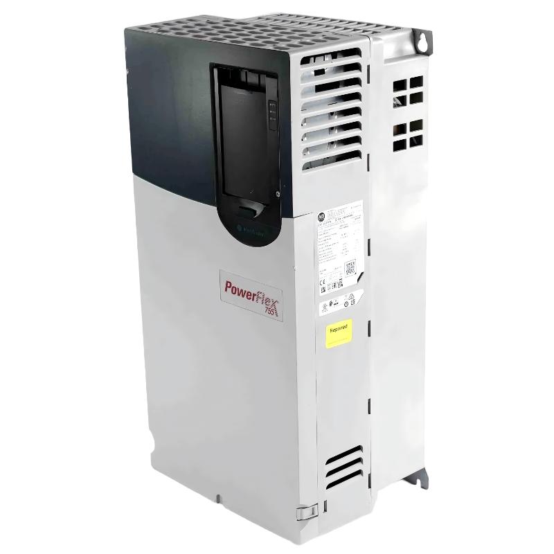
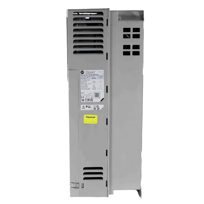
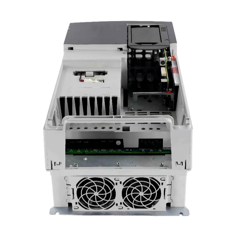
- Allen Bradley
- 20G14NF119JA0NNNNN
- PowerFlex AC Drive
- USA
- 665.5 × 308 × 346.4 mm
- 38.6kg
- Xiamen, China
- New & In Stock
- T/T, PayPal, Western Union
- 1 Year
- 1-3 Working Days
- DHL, UPS, TNT, FedEx and EMS.
- 24-Hour Service
- COO
- 32
Our advantage

Global Logistics
We have a 10-year logistics and express cooperation agreement, so our products can be shipped to any place in the world.

Brand new and original
Our products are imported in bulk from the place of origin. Because of the cooperative relationship, our products are all original and 100% new.

24-hour service
We provide 7*24 hours service to our customers. We will be there whenever you need us.

Price advantage
All our products are priced very favorably because we have our own warehouse and supply.
| Company Information | |||
| [email protected] | |||
| Mobile | +8615980777398 | ||
| +8615980777398 | |||
| 15980777398 |
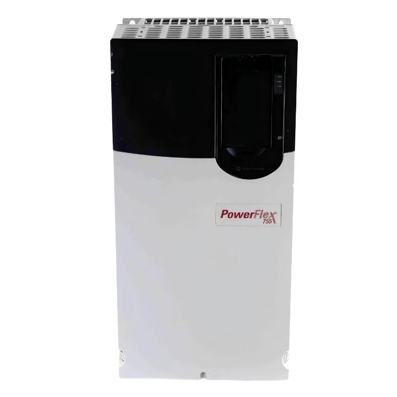
Allen-Bradley 20G14NF119JA0NNNNN – PowerFlex 755 Air-Cooled AC Drive
1. Product Overview
The Allen-Bradley 20G14NF119JA0NNNNN is a high-power PowerFlex 755 AC drive designed for demanding industrial motor-control applications. It is an air-cooled, open-type drive intended for three-phase 690 VAC systems and provides a 119 A Normal Duty output rating, corresponding to 110 kW Normal Duty power.
The drive is configured for DC input with precharge, making it particularly suitable for applications where the DC bus is supplied from a common DC system, regenerative power arrangement, or other DC-link architecture. The precharge arrangement helps control the initial charging of the DC bus and limits excessive inrush current during energization.
This particular configuration is a Frame 6 PowerFlex 755 drive. It includes an internal dynamic braking transistor, while the braking resistor itself is not included as an internal component. An external braking resistor can therefore be selected according to the application requirements and braking-energy calculation.
The unit is supplied as an open-type enclosure, with filtering and the CM jumper configuration already installed. It is also specified with embedded Ethernet communication capability, which makes it well suited to modern industrial automation systems where the drive needs to exchange commands, status information, diagnostics, and operating data with a controller or supervisory system.
The catalog number 20G14NF119JA0NNNNN represents a relatively high-capacity member of the PowerFlex 755 family. With its combination of 690 VAC operation, 119 A output current, 110 kW Normal Duty rating, 90 kW Heavy Duty rating, DC input, braking capability, and network integration, it is aimed at applications where a compact low-power inverter would not provide sufficient motor capacity or control capability.
2. Brand and Series
| Item | Specification |
|---|---|
| Brand | Allen-Bradley |
| Product Family | PowerFlex 750-Series |
| Product Series | PowerFlex 755 |
| Product Type | AC Drive / Variable Frequency Drive |
| Catalog Number | 20G14NF119JA0NNNNN |
| Drive Cooling | Air Cooled |
| Frame Size | Frame 6 |
| Input Configuration | DC Input with Precharge |
| Main Voltage Class | 690 VAC |
| Input Phase | 3 Phase |
| Enclosure Type | Open Type |
| Application Class | Industrial Motor Control |
The PowerFlex 755 series is intended for higher-performance industrial drive applications where motor speed, torque, acceleration, deceleration, process control, networking, and diagnostics are important.
Compared with compact general-purpose drives, the PowerFlex 755 platform is better suited to larger machines and more sophisticated automation systems. It is commonly considered for pumps, fans, conveyors, material-handling systems, compressors, mixers, process machinery, and other large motor applications.
3. Main Technical Parameters
| Parameter | Specification |
|---|---|
| Model / Part Number | 20G14NF119JA0NNNNN |
| Series | PowerFlex 755 |
| Brand | Allen-Bradley |
| Drive Type | AC Drive |
| Cooling Method | Air Cooled |
| Input Type | DC Input with Precharge |
| AC Voltage Class | 690 VAC |
| DC Voltage Rating | Approx. 932 VDC |
| Number of Input Phases | 3 Phase |
| Normal Duty Current | 119 A |
| Normal Duty Power | 110 kW |
| Heavy Duty Current | 98 A |
| Heavy Duty Power | 90 kW |
| Frame | Frame 6 |
| Enclosure | Open Type |
| Enclosure Protection | Open / IP00-type configuration |
| Dynamic Braking | Internal Braking Transistor |
| Internal Braking Resistor | Not Included |
| Filtering | Filtered |
| CM Jumper | Installed |
| HIM | Blank / No HIM |
| Communication | Embedded Ethernet capability |
| Cooling | Forced-air / air-cooled design |
| Operating Temperature | Approx. 0 to 50 °C |
| Relative Humidity | Approx. 5 to 95%, non-condensing |
| Storage Temperature | Approx. -40 to +70 °C |
| Approx. Dimensions | Approx. 665.5 H × 308 W × 346.4 D mm* |
| Approx. Weight | 14.51 kg* |
*Dimensions and weight should be treated as practical reference values for the drive configuration. Final cabinet layout, mounting clearance, shipping arrangement, and mechanical installation should be checked against the applicable dimensional drawing for the exact revision.
4. Electrical Rating
The most important electrical characteristic of the 20G14NF119JA0NNNNN is its high-current 690 VAC-class design.
The drive provides a 119 A Normal Duty rating and 110 kW Normal Duty power rating. This makes it appropriate for large motors and equipment where a lower-capacity PowerFlex unit would not provide enough continuous current.
For applications requiring a higher level of overload capability, the drive is rated at approximately 98 A and 90 kW in Heavy Duty operation.
| Duty Rating | Output Current | Power Rating | Typical Application Concept |
|---|---|---|---|
| Normal Duty | 119 A | 110 kW | Pumps, fans, conveyors and other variable-torque or normal-load machinery |
| Heavy Duty | 98 A | 90 kW | Higher-load machinery requiring greater overload capability |
The difference between Normal Duty and Heavy Duty ratings is important when selecting a drive. The motor nameplate current, load characteristics, acceleration requirements, overload requirements, operating cycle, and process conditions should all be considered rather than selecting the drive only by motor horsepower or kilowatt value.
For a 90 kW motor operating under demanding torque conditions, for example, the Heavy Duty rating can be more relevant than the 110 kW Normal Duty rating. Conversely, for a variable-torque pump or fan, the Normal Duty capacity can provide a larger usable motor range.
5. 690 VAC Three-Phase Design
The 20G14NF119JA0NNNNN is designed for a 690 VAC, three-phase industrial power system.
690 VAC is commonly encountered in larger industrial installations where higher system voltage is used to reduce current for a given power level. This can be useful for large motors because lower operating current can help reduce conductor size, voltage drop, and distribution losses when the electrical system is designed accordingly.
The 690 VAC rating also means that this drive should not be treated as a standard 400 VAC or 480 VAC drive. Motor voltage, transformer configuration, upstream protection, cable insulation, disconnect equipment, and the overall power-distribution system need to be compatible with the 690 VAC class.
The DC-side specification is approximately 932 VDC, which corresponds to the high-voltage DC-link environment associated with this class of drive.
6. DC Input with Precharge
One of the notable characteristics of this model is its DC input with precharge configuration.
Rather than relying on a conventional AC input arrangement alone, the drive is designed to operate from a DC bus. This can be particularly useful in systems where multiple drives share a common DC bus or where DC power is provided by a centralized front-end or other power-conversion equipment.
The precharge function is important because the DC bus contains significant capacitance. When the bus is first energized, the capacitors can otherwise draw a very large transient current. The precharge circuit controls this initial charging process before normal operation.
This type of configuration can be valuable in coordinated drive systems because a common DC architecture may allow energy to move between drives instead of treating every drive as an electrically isolated unit.
7. Internal Dynamic Braking Transistor
The JA0 configuration is important because it includes an internal dynamic braking transistor.
The braking transistor provides the switching function required to connect an external braking resistor to the DC bus when braking energy needs to be dissipated.
The resistor itself is not included internally. Instead, the braking resistor must be selected according to the required braking torque, stopping time, motor inertia, load inertia, duty cycle, and allowable braking energy.
| Braking Feature | 20G14NF119JA0NNNNN |
|---|---|
| Dynamic Braking Transistor | Included |
| Internal Braking Resistor | Not included |
| External Braking Resistor | Can be applied when required |
| Primary Purpose | Dissipation of regenerated braking energy |
| Typical Applications | Fast stopping, high-inertia loads, conveyors, hoists and other braking-intensive machinery |
This makes the JA0 configuration particularly interesting when the application needs controlled deceleration or rapid stopping.
It is important not to confuse the braking transistor with the braking resistor. The transistor is the electronic switching device inside the drive. The resistor is the external energy-dissipation component used to convert regenerated electrical energy into heat.
8. Air-Cooled Construction
The 20G14NF119JA0NNNNN uses an air-cooled architecture.
Air cooling is widely used for industrial variable-frequency drives because it provides a practical balance between thermal performance, maintenance, installation cost, and serviceability.
For a 110 kW-class drive, heat management is a major part of system design. The drive produces heat through semiconductor switching losses, conduction losses, control electronics, and other internal losses.
The cabinet or enclosure therefore needs to provide sufficient ventilation and clearance. Ambient temperature, airflow direction, cabinet arrangement, dust loading, altitude, and nearby heat-generating equipment can all influence actual thermal performance.
A drive that is electrically correctly sized can still experience thermal problems if the installation does not provide adequate ventilation.
9. Open-Type Enclosure
This model uses an open-type enclosure configuration.
An open-type drive is normally intended to be installed inside a suitable electrical cabinet, control enclosure, motor-control center, or other protected installation environment rather than being exposed directly to harsh industrial conditions.
The cabinet designer needs to provide suitable protection against dust, moisture, accidental contact, conductive contamination, and other environmental hazards.
The open construction also gives system designers more flexibility because the drive can be integrated into a larger electrical-control assembly with external disconnects, fuses or circuit breakers, contactors where appropriate, braking components, control equipment, PLC hardware, networking equipment, and other accessories.
10. Filtering and CM Jumper
The catalog configuration specifies filtering with the CM jumper installed.
Filtering is important in industrial drive systems because high-frequency switching from the power semiconductors can produce electrical noise. Proper filtering and grounding practices help manage electromagnetic interference and improve system compatibility.
The common-mode configuration is also relevant because drive systems can generate high-frequency common-mode currents through motor cables and motor bearings.
Correct cable selection, grounding, bonding, cabinet construction, motor-frame grounding, and installation practices should therefore be considered together with the drive’s internal filtering configuration.
11. HIM Configuration
The 20G14NF119JA0NNNNN is supplied with a blank configuration / no HIM.
HIM refers to the Human Interface Module normally used for local drive interaction.
A drive without a door-mounted HIM is often appropriate where the drive is controlled from a PLC, HMI, DCS, SCADA system, or other remote automation platform.
This configuration can also simplify a centralized control-panel design. Local control can be implemented through the automation system while the drive handles motor control, diagnostics, status information, and protection functions.
12. Embedded Ethernet Capability
The drive is configured with embedded Ethernet communication capability, providing a practical connection point for industrial automation networks.
This can be useful for applications in which the drive needs to communicate with a controller or supervisory system rather than being operated manually from the front of the drive.
Typical information exchanged in a networked drive system can include:
- Start and stop commands.
- Speed reference.
- Frequency reference.
- Motor current.
- Output frequency.
- Drive status.
- Fault information.
- Warning information.
- Diagnostic data.
- Acceleration and deceleration parameters.
- Process-related operating information.
The networking capability is especially useful when multiple drives are installed throughout a plant and operators need centralized visibility into machine operation.
13. Product Introduction
The 20G14NF119JA0NNNNN is best viewed as a high-capacity industrial motor-control solution rather than simply a frequency converter.
Its 119 A Normal Duty rating places it in a range suitable for large industrial motors. The 690 VAC operating class makes it appropriate for high-voltage industrial motor systems, while the 110 kW Normal Duty rating provides substantial power capacity.
The combination of DC input, precharge, internal braking transistor, embedded Ethernet capability, filtering, and air cooling gives the drive a configuration suitable for engineered automation systems.
This is particularly useful when the drive must become part of a larger machine or process rather than operate as an isolated motor controller.
14. Typical Applications
Large Pump Systems
The drive can be used for large pump systems where variable-speed operation is required.
Typical examples include:
- Water circulation.
- Industrial process pumps.
- Cooling-water pumps.
- Water-treatment systems.
- Irrigation systems.
- Large booster pumps.
Variable-speed control can allow the pump to match process demand more closely than a simple fixed-speed motor arrangement.
Large Fans and Blowers
Large fans and blowers are another natural application.
Examples include:
- Industrial ventilation.
- Furnace air systems.
- Cooling towers.
- Dust-extraction systems.
- Process-air systems.
- Large exhaust systems.
For variable-torque loads such as many fan applications, speed control can significantly change the operating point of the machine.
Conveyors
The drive is also suitable for large conveyor systems.
Conveyors may require controlled acceleration and deceleration to prevent:
- Mechanical shock.
- Belt slippage.
- Product movement.
- Excessive gearbox loading.
- Unnecessary current peaks.
The integrated braking transistor can also be useful when a conveyor requires controlled deceleration or additional braking capability.
Material Handling
Heavy material-handling machinery can benefit from the high current capability of this drive.
Potential applications include:
- Large transfer systems.
- Bulk-material conveyors.
- Processing equipment.
- Industrial lifting-related machinery.
- Large material-feeding systems.
The final drive selection should always consider the actual torque requirements and overload profile rather than simply matching the motor’s kW rating.
Compressors
Large industrial compressors can require significant starting torque and continuous motor current.
The PowerFlex 755 platform can provide adjustable acceleration, deceleration, speed control, monitoring, and integration with the plant automation system.
For compressor applications, the actual motor starting requirements, load profile, minimum and maximum speed, and process-control requirements should be evaluated carefully.
Mixers and Process Machinery
Large mixers, agitators, processing machines, and other rotating equipment can require both speed control and overload capability.
The 110 kW Normal Duty rating and 90 kW Heavy Duty rating provide flexibility for different load conditions.
Industrial Production Lines
The drive can also be integrated into larger production systems where several motors must operate together.
Ethernet communication can allow the drive to exchange operating data with the machine controller, while the drive itself manages the motor-control function.
15. Main Product Advantages
1. High Power Capacity
The first major advantage is the relatively high power capacity.
At 110 kW Normal Duty, the drive can handle large industrial motors that are beyond the practical range of many compact drive families.
2. 690 VAC Compatibility
The 690 VAC design allows the drive to be used in high-voltage industrial motor systems.
This is especially valuable in larger facilities where 690 VAC motor distribution is already part of the plant electrical architecture.
3. DC Bus Architecture
The DC-input configuration makes the drive suitable for applications using a common DC bus or other DC power architecture.
This can provide additional flexibility when several drives are coordinated within the same power system.
4. Built-In Dynamic Braking Transistor
The internal braking transistor is a significant advantage for applications requiring controlled braking.
An external braking resistor can be selected according to the actual braking-energy requirements instead of requiring the drive itself to contain a fixed internal resistor.
5. Network Integration
Embedded Ethernet capability allows the drive to fit naturally into a modern industrial automation system.
This reduces dependence on purely local drive operation and allows centralized monitoring and control.
6. Industrially Proven Drive Platform
The PowerFlex 755 platform is designed for industrial applications where motor control, diagnostics, networking, and configuration flexibility are important.
It is therefore more suitable for engineered machine systems than a simple low-cost variable-speed drive intended only for basic speed adjustment.
7. Open-Type Cabinet Integration
The open-type design makes it possible to integrate the drive into a larger electrical control system.
For OEMs and system integrators, this can be advantageous because the drive can be combined with other control and protection equipment inside a properly designed enclosure.
8. Air-Cooled Design
Air cooling avoids the complexity of liquid cooling and provides a practical solution for many industrial installations.
Proper cabinet ventilation and thermal management remain essential, especially for a high-power drive.
16. Installation Considerations
A drive of this capacity requires more attention to installation than a small 5 kW or 15 kW inverter.
The incoming DC supply must be compatible with the drive’s DC voltage requirements and precharge arrangement.
The motor must also be appropriate for the output voltage and current characteristics of the drive.
The cabinet must provide adequate ventilation, clearance, grounding, and protection.
The following points should be considered during engineering:
| Installation Item | Recommended Engineering Consideration |
|---|---|
| Incoming Power | Verify DC bus voltage and available fault current |
| Motor | Check motor voltage, current, frequency, power and duty |
| Drive Rating | Select according to actual Normal Duty or Heavy Duty requirements |
| Braking | Calculate braking energy and select external resistor if required |
| Cabinet | Provide appropriate enclosure and environmental protection |
| Cooling | Ensure sufficient airflow and heat dissipation |
| Grounding | Provide proper protective and high-frequency grounding |
| Motor Cable | Use suitable cable for the drive output and installation environment |
| Communication | Confirm Ethernet network architecture and control requirements |
| Maintenance | Provide adequate access for inspection and service |
| Clearance | Follow the applicable installation drawing and thermal-clearance requirements |
17. Dimensions and Weight
For planning purposes, the drive is a Frame 6 unit.
A practical reference envelope is approximately:
665.5 mm H × 308 mm W × 346.4 mm D
The approximate product weight is:
14.51 kg
| Mechanical Parameter | Approximate Value |
|---|---|
| Model / Part Number | 20G14NF119JA0NNNNN |
| Frame Size | Frame 6 |
| Height | Approx. 665.5 mm |
| Width | Approx. 308 mm |
| Depth | Approx. 346.4 mm |
| Weight | Approx. 14.51 kg |
| Installation Type | Cabinet / panel integration |
| Cooling | Air Cooled |
| Enclosure | Open Type |
For final mechanical fabrication, the exact dimensional drawing should be used rather than relying only on catalog-level dimensions. Mounting-hole positions, cable entry, terminal access, ventilation clearance, and service space are especially important when preparing a cabinet.
18. Recommended Same-Series Models
The following models are useful alternatives or comparison points within the PowerFlex 755 / 690 VAC DC-input family.
| Model / Part Number | Voltage | Normal Duty Current | Normal Duty Power | Heavy Duty Current | Heavy Duty Power | Typical Position |
|---|---|---|---|---|---|---|
| 20G14NF061JN0NNNNN | 690 VAC | 61 A | 55 kW | 50 A | 45 kW | Lower-power alternative |
| 20G14NF082JN0NNNNN | 690 VAC | 82 A | 75 kW | 61 A | 55 kW | Medium-power alternative |
| 20G14NF098JN0NNNNN | 690 VAC | 98 A | 90 kW | 82 A | 75 kW | Closest lower-current option |
| 20G14NF142JN0NNNNN | 690 VAC | 142 A | 132 kW | 119 A | 110 kW | Higher-power alternative |
| 20G14NF171JN0NNNNN | 690 VAC | 171 A | 160 kW | 142 A | 132 kW | Larger-capacity option |
These models are particularly useful when the motor current is close to the limit of the 119 A drive.
For example, if the motor’s actual operating current is comfortably below 98 A, the 20G14NF098JN0NNNNN may be worth considering.
If the motor requires more than the available 119 A Normal Duty capacity, moving upward to the 20G14NF142JN0NNNNN provides additional current and power capacity.
The 20G14NF061JN0NNNNN and 20G14NF082JN0NNNNN provide lower-capacity options when the 119 A drive would otherwise be oversized.
19. Same-Series Model Comparison
| Model / Part Number | Normal Duty Power | Heavy Duty Power | Normal Duty Current | Heavy Duty Current |
|---|---|---|---|---|
| 20G14NF061JN0NNNNN | 55 kW | 45 kW | 61 A | 50 A |
| 20G14NF082JN0NNNNN | 75 kW | 55 kW | 82 A | 61 A |
| 20G14NF098JN0NNNNN | 90 kW | 75 kW | 98 A | 82 A |
| 20G14NF119JA0NNNNN | 110 kW | 90 kW | 119 A | 98 A |
| 20G14NF142JN0NNNNN | 132 kW | 110 kW | 142 A | 119 A |
| 20G14NF171JN0NNNNN | 160 kW | 132 kW | 171 A | 142 A |
This comparison shows where the 20G14NF119JA0NNNNN sits within the larger 690 VAC PowerFlex 755 range.
It is positioned above the 98 A / 90 kW Normal Duty model and below the 142 A / 132 kW Normal Duty model.
That makes it a useful selection for installations where approximately 100–120 A of Normal Duty output is required.
20. JA0 Versus JN0 Configuration
One important point when comparing PowerFlex 755 catalog numbers is the difference between the JA0 and JN0 configurations.
| Feature | 20G14NF119JA0NNNNN | 20G14NF119JN0NNNNN |
|---|---|---|
| Model / Part Number | 20G14NF119JA0NNNNN | 20G14NF119JN0NNNNN |
| Voltage | 690 VAC | 690 VAC |
| Normal Duty Current | 119 A | 119 A |
| Normal Duty Power | 110 kW | 110 kW |
| Heavy Duty Current | 98 A | 98 A |
| Heavy Duty Power | 90 kW | 90 kW |
| Input | DC with Precharge | DC with Precharge |
| Frame | Frame 6 | Frame 6 |
| Cooling | Air Cooled | Air Cooled |
| Filtering | Filtered | Filtered |
| CM Jumper | Installed | Installed |
| HIM | Blank / No HIM | Blank / No HIM |
| Dynamic Braking Transistor | Included | Not included |
| Internal Braking Resistor | Not included | Not included |
The primary practical difference is the dynamic-braking configuration.
The JA0 version includes the internal braking transistor, making it the more appropriate choice when the application needs dynamic braking and an external braking resistor will be connected.
The JN0 version does not include that internal braking transistor.
Therefore, the catalog suffix should not be ignored when replacing an existing drive. A drive with the same current and voltage rating can still have a different functional configuration.
21. Five Popular Same-Brand Models
The following are useful popular models from the same Allen-Bradley product range and related drive families.
| Model / Part Number | Series | Voltage Class | Current Class | Approx. Power Class | Cooling | Typical Use |
|---|---|---|---|---|---|---|
| 25B-D017N114 | PowerFlex 525 | 480 VAC class | 17 A class | Approx. 7.5 kW class | Air Cooled | Pumps, conveyors, fans, machinery |
| 25B-D024N114 | PowerFlex 525 | 480 VAC class | 24 A class | Approx. 11 kW class | Air Cooled | General machine control |
| 25B-D030N114 | PowerFlex 525 | 480 VAC class | 30 A class | Approx. 15 kW class | Air Cooled | Industrial machinery and process equipment |
| 20G11NC5P0JA0NNNNN | PowerFlex 755 | 480 VAC class | 50 A class | Approx. 37–45 kW class | Air Cooled | Larger industrial motors |
| 20G11NC072JA0NNNNN | PowerFlex 755 | 480 VAC class | 72 A class | Approx. 55 kW class | Air Cooled | High-capacity industrial motor control |
These models cover a much wider power range than the 20G14NF119JA0NNNNN.
The PowerFlex 525 models are generally more appropriate for compact machines and lower-power applications.
The PowerFlex 755 models are more appropriate when the system requires higher power, greater control flexibility, larger motors, advanced networking, or more sophisticated industrial integration.
22. Popular Model Mechanical Reference
Exact dimensions and weights vary according to frame size, voltage class, configuration, options, and revision. For that reason, the following table is intended as a selection reference rather than a cabinet-fabrication drawing.
| Model / Part Number | Series | Frame / Size Class | Dimensions | Weight |
|---|---|---|---|---|
| 25B-D017N114 | PowerFlex 525 | Frame-dependent | Configuration dependent | Configuration dependent |
| 25B-D024N114 | PowerFlex 525 | Frame-dependent | Configuration dependent | Configuration dependent |
| 25B-D030N114 | PowerFlex 525 | Frame-dependent | Configuration dependent | Configuration dependent |
| 20G11NC5P0JA0NNNNN | PowerFlex 755 | Frame-dependent | Configuration dependent | Configuration dependent |
| 20G11NC072JA0NNNNN | PowerFlex 755 | Frame-dependent | Configuration dependent | Configuration dependent |
For engineering drawings, cabinet fabrication, shipping calculations, and mounting hardware selection, the exact model-specific dimensional data should always take priority over generalized frame information.
23. Selecting the Correct Model
When selecting between the related PowerFlex 755 models, motor current should normally be one of the first values checked.
For example:
| Motor Requirement | Possible Selection Direction |
|---|---|
| Up to approximately 55 kW ND | 20G14NF061JN0NNNNN class |
| Up to approximately 75 kW ND | 20G14NF082JN0NNNNN class |
| Up to approximately 90 kW ND | 20G14NF098JN0NNNNN class |
| Up to approximately 110 kW ND | 20G14NF119JA0NNNNN class |
| Up to approximately 132 kW ND | 20G14NF142JN0NNNNN class |
| Up to approximately 160 kW ND | 20G14NF171JN0NNNNN class |
However, motor kW alone should not determine the final selection.
Motor nameplate current, motor voltage, service factor, acceleration time, load inertia, speed range, overload requirements, braking requirements, ambient temperature, altitude, and operating cycle can all affect the appropriate drive size.
24. Maintenance Considerations
The air-cooled architecture means that cleanliness and airflow are important.
Dust accumulation around cooling paths can reduce heat transfer and eventually increase operating temperature.
Routine maintenance should therefore include:
- Inspection of cooling airflow.
- Inspection of ventilation openings.
- Checking for excessive dust accumulation.
- Inspection of electrical connections.
- Checking cabinet temperature.
- Inspecting motor cables.
- Checking grounding connections.
- Reviewing drive fault history.
- Inspecting braking components where installed.
- Checking cooling fans and associated airflow.
For high-power industrial drives, preventive maintenance is usually more economical than waiting for a thermal or electrical failure to interrupt production.
25. Why This Model Is a Good Choice for Large Industrial Systems
The 20G14NF119JA0NNNNN combines several characteristics that make it well suited to large industrial equipment.
Its 119 A Normal Duty rating provides substantial motor capacity.
Its 690 VAC rating allows it to work within higher-voltage industrial distribution systems.
Its DC-input configuration makes it useful for common-DC-bus architectures.
Its internal dynamic braking transistor provides additional flexibility for braking-intensive applications.
Its Ethernet capability makes it easier to integrate into centralized automation systems.
Its air-cooled Frame 6 construction provides a practical solution for cabinet-mounted industrial equipment.
The combination is particularly useful for machinery that needs more than basic speed control and where the drive is expected to participate actively in the overall machine-control architecture.
26. Technical Summary
| Category | Specification |
|---|---|
| Model / Part Number | 20G14NF119JA0NNNNN |
| Brand | Allen-Bradley |
| Series | PowerFlex 755 |
| Family | PowerFlex 750-Series |
| Product | PowerFlex 755 AC Drive |
| Cooling | Air Cooled |
| Input | DC Input with Precharge |
| Voltage | 690 VAC |
| DC Voltage Class | Approx. 932 VDC |
| Phases | 3 Phase |
| Normal Duty Current | 119 A |
| Normal Duty Power | 110 kW |
| Heavy Duty Current | 98 A |
| Heavy Duty Power | 90 kW |
| Frame | Frame 6 |
| Enclosure | Open Type |
| Filtering | Yes |
| CM Jumper | Installed |
| Dynamic Braking | Internal Transistor Included |
| Braking Resistor | External / Not Internally Included |
| HIM | Blank / No HIM |
| Communication | Embedded Ethernet capability |
| Operating Temperature | Approx. 0–50 °C |
| Humidity | Approx. 5–95%, non-condensing |
| Storage Temperature | Approx. -40 to +70 °C |
| Approx. Dimensions | 665.5 × 308 × 346.4 mm |
| Approx. Weight | 14.51 kg |
| Primary Application | Large industrial motor control |
27. Final Product Assessment
The Allen-Bradley 20G14NF119JA0NNNNN is a high-capacity PowerFlex 755 air-cooled AC drive intended for industrial motor-control applications where a combination of high power, 690 VAC operation, DC-bus capability, braking functionality, and network integration is required.
Its 119 A / 110 kW Normal Duty rating makes it suitable for large industrial motors, while its 98 A / 90 kW Heavy Duty rating provides a separate selection point for applications with more demanding load characteristics.
The JA0 configuration is especially relevant because it includes an internal dynamic braking transistor. When an application requires rapid or controlled deceleration, an appropriately sized external braking resistor can be incorporated into the system.
The DC input with precharge configuration is another important feature. It allows the drive to be considered for common-DC-bus and other engineered DC-link systems rather than limiting it to a conventional standalone AC-input arrangement.
The integrated Ethernet capability is also valuable in modern factories. The drive can be incorporated into a larger control architecture where motor speed, current, status, alarms, faults, and operating commands need to be monitored or exchanged through the automation network.
From a mechanical perspective, the Frame 6 air-cooled construction makes the unit suitable for cabinet-based industrial installations. Because the enclosure is open type, the surrounding cabinet must provide the required environmental protection, ventilation, clearance, grounding, and service access.
Overall, the 20G14NF119JA0NNNNN is best suited to large pumps, fans, blowers, conveyors, compressors, material-handling equipment, mixers, process machinery, and other high-power industrial systems where reliable variable-speed motor control and integration with a larger automation system are important.
For replacement work, the complete catalog number should be matched rather than selecting a drive only by kW or current. The difference between the JA0 and JN0 configurations is a good example: two drives can have the same 690 VAC, 119 A, and 110 kW ratings while having different dynamic-braking configurations.
In practical terms, the 20G14NF119JA0NNNNN is a strong choice when the project calls for a 690 VAC, 119 A, 110 kW Normal Duty PowerFlex 755 drive with DC input and precharge, air cooling, Frame 6 construction, embedded Ethernet capability, filtering, no HIM, and an internal dynamic braking transistor.