

ProductPRODUCT
Featured products








Contact Us
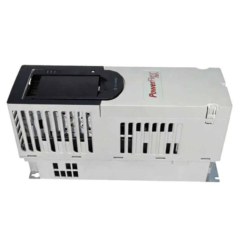
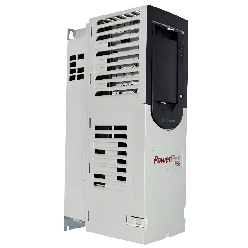
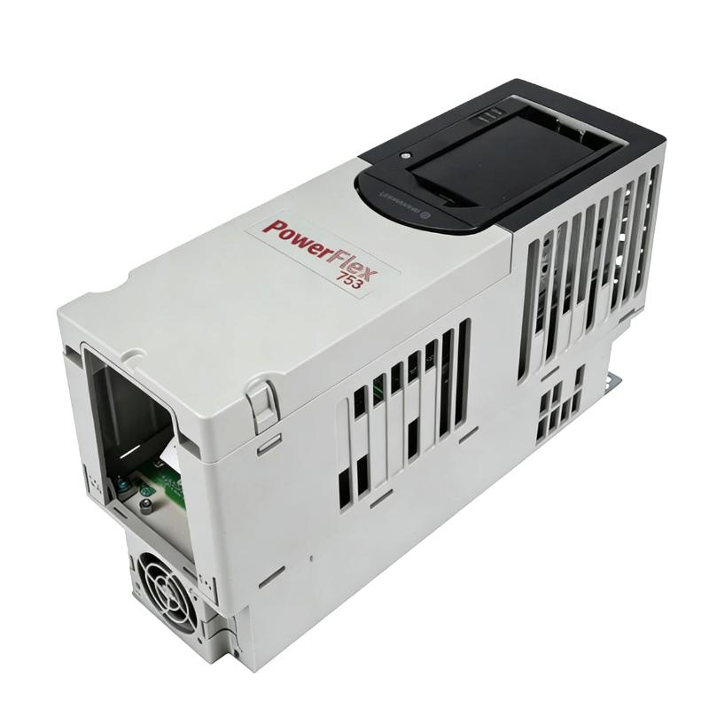
- Allen Bradley
- 20G11RC8P7AA0NNNNN
- PowerFlex AC Drive
- USA
- 400.5 × 110 × 211 mm
- 3.59kg
- Xiamen, China
- New & In Stock
- T/T, PayPal, Western Union
- 1 Year
- 1-3 Working Days
- DHL, UPS, TNT, FedEx and EMS.
- 24-Hour Service
- COO
- 69
Our advantage

Global Logistics
We have a 10-year logistics and express cooperation agreement, so our products can be shipped to any place in the world.

Brand new and original
Our products are imported in bulk from the place of origin. Because of the cooperative relationship, our products are all original and 100% new.

24-hour service
We provide 7*24 hours service to our customers. We will be there whenever you need us.

Price advantage
All our products are priced very favorably because we have our own warehouse and supply.
| Company Information | |||
| [email protected] | |||
| Mobile | +8615980777398 | ||
| +8615980777398 | |||
| 15980777398 |
1. Basic Product Information
| Parameter | Specification |
|---|---|
| Model | 20G11RC8P7AA0NNNNN |
| Brand | Allen-Bradley |
| Product family | PowerFlex |
| Product series | PowerFlex 755 |
| Series family | PowerFlex 750-Series |
| Product type | AC Variable Frequency Drive |
| Drive type | Industrial AC Drive |
| Voltage class | 400 VAC |
| Input phase | Three-phase |
| Rated output current | 8.7 A |
| Normal-duty power | 4.0 kW |
| Heavy-duty power | 2.2 kW |
| Frame | Frame 1 |
| Cooling method | Forced air |
| Enclosure | IP20 |
| Enclosure style | Open Type / NEMA/UL Open Type |
| Communication | Embedded EtherNet/IP |
| Dynamic braking | Internal dynamic braking transistor |
| HIM configuration | Blank / No HIM |
| Input arrangement | AC input with precharge and DC terminals |
| EMC filtering | Filtered |
| CM jumper | Configuration-dependent; catalog configuration uses the specified filter arrangement |
| Installation | Electrical cabinet / panel mounting |
| Main application | Industrial motor speed and torque control |
| Approx. dimensions | 400.5 × 110 × 211 mm |
| Approx. weight | 3.59 kg |
| Mounting orientation | Vertical |
2. Product Introduction
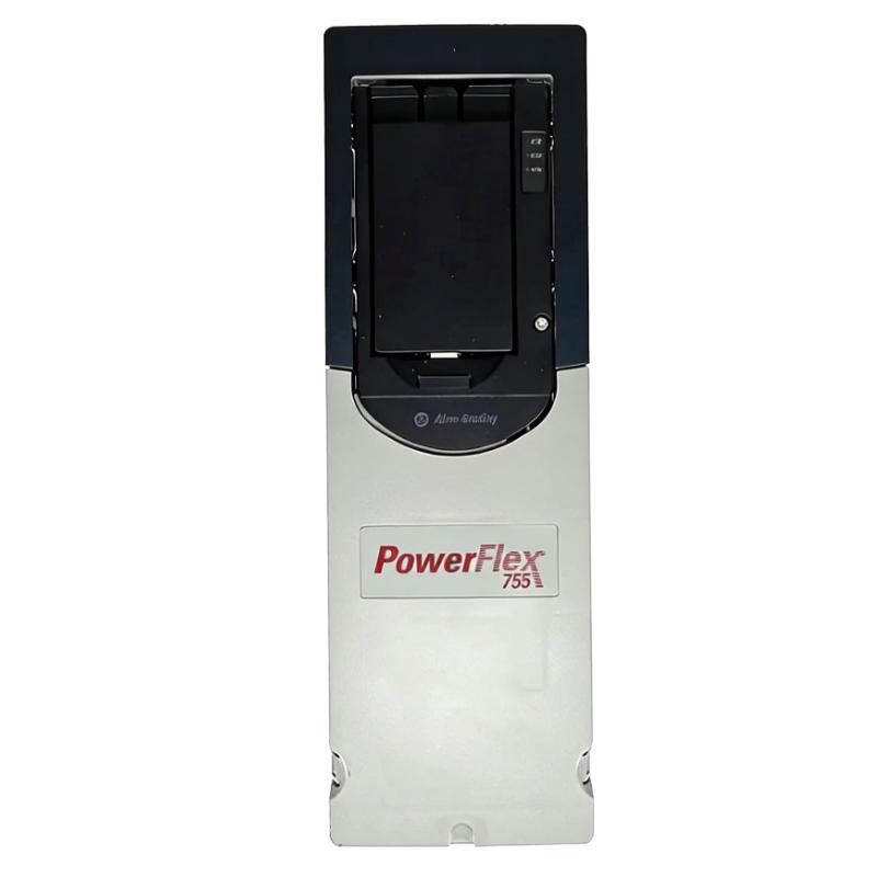
The 20G11RC8P7AA0NNNNN is a PowerFlex 755 AC variable frequency drive designed for industrial three-phase motor control.
It belongs to the PowerFlex 755 family, a high-performance drive platform intended for applications where motor speed, torque, acceleration, deceleration, process control, communications, diagnostics and system integration are important.
This particular model is configured for a 400 VAC three-phase supply and provides an output current rating of approximately 8.7 A.
Its normal-duty motor capacity is approximately 4.0 kW, while the heavy-duty rating is approximately 2.2 kW.
The drive uses a Frame 1 construction and forced-air cooling, making it suitable for installation inside an industrial control cabinet.
The compact frame size is useful when the machine builder needs advanced drive functionality without using a larger physical drive enclosure.
The model also incorporates embedded EtherNet/IP communication, allowing the drive to participate directly in an industrial automation network.
This is especially useful in modern production machinery where the motor drive needs to exchange commands, speed references, operating status, faults and diagnostic information with the machine control system.
3. Brand and Series
| Item | Description |
|---|---|
| Brand | Allen-Bradley |
| Product family | PowerFlex |
| Series | PowerFlex 755 |
| Series group | PowerFlex 750-Series |
| Product category | AC Variable Frequency Drives |
| Application level | Industrial / high-performance drive |
| Typical control system | Automated industrial machinery |
| Typical motor type | Three-phase AC motor |
The PowerFlex 755 series is designed for applications requiring more functionality than a basic variable-speed drive.
It is particularly suitable when the drive is expected to communicate with a controller, provide detailed diagnostics, support advanced motor-control methods, and adapt to different machine operating requirements.
4. Detailed Technical Parameters
| Technical Parameter | Specification |
|---|---|
| Model | 20G11RC8P7AA0NNNNN |
| Brand | Allen-Bradley |
| Series | PowerFlex 755 |
| Voltage class | 400 VAC |
| Input voltage | 400 VAC class |
| Input phase | 3-phase AC |
| Input frequency | 50/60 Hz |
| Output phase | 3-phase AC |
| Output current | 8.7 A |
| Normal-duty rating | 4.0 kW |
| Heavy-duty rating | 2.2 kW |
| Frame size | Frame 1 |
| Cooling | Forced air |
| Enclosure | IP20 |
| Enclosure classification | NEMA/UL Open Type |
| Input precharge | Yes |
| DC bus terminals | Yes |
| Dynamic braking transistor | Yes |
| EMC filter | Yes |
| Communication | Embedded EtherNet/IP |
| Human interface module | Blank / No HIM |
| V/Hz control | Supported |
| Sensorless vector control | Supported |
| Advanced vector control | Supported |
| PID control | Supported |
| Auto tuning | Supported |
| Flying start | Supported |
| Acceleration control | Programmable |
| Deceleration control | Programmable |
| Electronic overload protection | Supported |
| Motor protection | Supported |
| Fault diagnostics | Supported |
| Network monitoring | Supported |
| Approx. height | 400.5 mm |
| Approx. width | 110 mm |
| Approx. depth | 211 mm |
| Approx. dimensions | 400.5 × 110 × 211 mm |
| Approx. weight | 3.59 kg |
| Installation | Vertical |
| Cooling airflow | Forced air |
| Typical mounting | Cabinet / panel |
| Main application | Industrial motor control |
5. Electrical Rating
The most important electrical characteristic of the 20G11RC8P7AA0NNNNN is its approximately 8.7 A output current rating.
For normal-duty applications, the drive is generally associated with a motor capacity of approximately 4.0 kW.
For heavy-duty applications, the applicable motor rating is approximately 2.2 kW.
The distinction between normal duty and heavy duty is important.
A motor may have a relatively low nominal power rating but still require high starting torque or frequent overload capability.
For this reason, the motor’s actual rated current should always be considered during drive selection.
| Electrical Item | Value |
|---|---|
| Model | 20G11RC8P7AA0NNNNN |
| Voltage class | 400 VAC |
| Input | 3-phase |
| Frequency | 50/60 Hz |
| Output current | 8.7 A |
| Normal-duty motor rating | 4.0 kW |
| Heavy-duty motor rating | 2.2 kW |
| Output | Variable-frequency 3-phase AC |
| Motor speed | Adjustable |
| Acceleration | Programmable |
| Deceleration | Programmable |
| Dynamic braking | Available through internal braking transistor |
6. Normal-Duty Operation
The normal-duty rating of approximately 4.0 kW makes this model suitable for a broad range of general industrial machinery.
Typical normal-duty loads include:
- Conveyors
- Fans
- Pumps
- Rollers
- Feeders
- Packaging machinery
- Material-handling equipment
- Small processing machines
- General rotating machinery
In these applications, the drive can adjust motor speed according to the machine’s operating requirements.
For example, a conveyor can operate at a low speed during setup and increase speed during normal production.
A fan can reduce speed when less airflow is required.
A pump can change speed according to pressure or flow requirements.
7. Heavy-Duty Operation
The heavy-duty rating is approximately 2.2 kW.
Heavy-duty operation is relevant when the motor or machine experiences demanding operating conditions.
Examples include:
- Frequent acceleration
- Frequent deceleration
- High starting torque
- High mechanical inertia
- Sudden changes in load
- Repetitive start/stop cycles
- Material-handling systems
- Loaded conveyors
- Feed mechanisms
In these cases, the drive should be selected according to the actual motor current and overload requirements rather than simply matching the motor’s kW rating.
8. Physical Dimensions
The drive uses a Frame 1 mechanical configuration.
A practical reference for the drive dimensions is approximately:
400.5 mm × 110 mm × 211 mm
This corresponds to approximately:
15.77 in × 4.33 in × 8.31 in
| Mechanical Parameter | Specification |
|---|---|
| Model | 20G11RC8P7AA0NNNNN |
| Frame | Frame 1 |
| Height | Approx. 400.5 mm |
| Width | Approx. 110 mm |
| Depth | Approx. 211 mm |
| Overall size | Approx. 400.5 × 110 × 211 mm |
| Approx. height | 15.77 in |
| Approx. width | 4.33 in |
| Approx. depth | 8.31 in |
| Approx. weight | 3.59 kg |
| Cooling | Forced air |
| Mounting | Vertical cabinet mounting |
The cabinet should not be designed with exactly the same dimensions as the drive.
Additional space is required for wiring, airflow, maintenance and connection access.
The actual cabinet dimensions should also account for circuit protection equipment, terminals, controllers, contactors, communication equipment and other devices installed in the same enclosure.
9. Weight
The approximate product weight is:
3.59 kg
This figure should be treated as an approximate drive-unit weight.
Shipping weight can be higher because it may include:
- Packaging
- Protective materials
- Documentation
- Mounting accessories
- Carton
For cabinet design and equipment handling, the drive-unit weight is the more useful value.
10. Enclosure and Installation
The drive has an IP20 / NEMA/UL Open Type configuration.
This means it is intended for installation in a suitable protected environment.
It is not designed to be directly exposed to:
- Rain
- Water spray
- Outdoor weather
- Heavy dust
- Conductive particles
- Aggressive chemical environments
A properly selected electrical enclosure should therefore be used when the surrounding environment does not meet the drive’s environmental requirements.
The enclosure should also provide sufficient ventilation.
11. Cooling System
The drive uses forced-air cooling.
During operation, electrical power is converted from the incoming AC supply into controlled electrical output for the motor.
Some energy is lost as heat inside the drive.
The cooling system removes this heat.
Good airflow is therefore essential.
The control cabinet should provide adequate air circulation and should not block the drive’s cooling path.
When several drives are installed in the same cabinet, the total heat generated by all devices should be considered.
12. Embedded EtherNet/IP Communication
One of the most useful characteristics of this model is its embedded EtherNet/IP communication capability.
The drive can be integrated into an industrial automation network.
This allows a controller to exchange information with the drive.
Typical information includes:
| Data | Typical Function |
|---|---|
| Start command | Starts motor operation |
| Stop command | Stops motor operation |
| Speed reference | Sets motor speed |
| Direction command | Controls motor direction |
| Actual speed | Monitors motor speed |
| Output current | Monitors motor load |
| Drive status | Determines operating state |
| Warning status | Monitors potential problems |
| Fault status | Identifies drive faults |
| Diagnostic information | Supports maintenance |
| Parameter information | Supports configuration |
This network integration is particularly valuable in automated manufacturing equipment.
Instead of relying entirely on individual hardwired control signals, the automation system can exchange drive data through the network.
13. Motor Control
The PowerFlex 755 platform supports multiple motor-control methods.
This flexibility allows the same drive family to be used in different applications.
V/Hz Control
V/Hz control is suitable for relatively simple motor applications.
Typical examples include:
- Fans
- Pumps
- Basic conveyors
- Simple rotating equipment
It is straightforward and appropriate where advanced torque control is not required.
Sensorless Vector Control
Sensorless vector control provides improved motor performance compared with basic V/Hz control.
It can provide better torque characteristics at lower speeds and is useful for applications such as:
- Conveyors
- Feeders
- Material handling
- Machine machinery
- Variable-load systems
Advanced Vector Control
More advanced vector-control functions can be used when the machine requires better torque and speed regulation.
Potential applications include:
- High-performance conveyors
- Processing machinery
- Material handling
- High-inertia machinery
- Machinery requiring controlled torque
The actual performance depends on motor characteristics, drive configuration and application setup.
14. PID Process Control
The drive can also be used in process-control applications through PID functions.
A typical example is a pump system.
A pressure sensor measures actual system pressure.
The drive compares the measured pressure with the desired setpoint.
If the pressure is too low, motor speed can increase.
If the pressure is too high, motor speed can decrease.
This creates an automatic control loop.
Typical applications include:
- Pressure control
- Flow control
- Water circulation
- Cooling systems
- Airflow control
- Process pumping
15. Dynamic Braking
The model includes an internal dynamic braking transistor.
Dynamic braking can be useful when the motor needs to decelerate quickly.
During motor deceleration, mechanical energy can be transferred into the drive’s DC bus.
A suitable braking resistor can dissipate this energy as heat.
This can provide improved stopping performance for machines with high inertia.
Typical applications include:
- Conveyors
- Rollers
- Material-handling machines
- High-inertia rotating equipment
- Repetitive start/stop machinery
- Feed systems
The braking resistor must be correctly selected for the machine’s actual braking energy and duty cycle.
16. Product Applications
Conveyor Systems
The drive is well suited to conveyor systems where speed control and smooth acceleration are important.
A conveyor can be programmed to accelerate gradually.
This reduces mechanical shock to:
- Belts
- Gearboxes
- Couplings
- Rollers
- Bearings
- Mechanical drive components
The motor speed can also be adjusted according to production requirements.
Pump Systems
The drive can regulate pump speed according to pressure or flow requirements.
Instead of running the pump continuously at maximum speed, the motor can operate at a lower speed when demand decreases.
This is especially useful for variable-flow applications.
Fan Systems
Industrial ventilation systems often require variable airflow.
The drive can control fan speed according to demand.
This can be useful in:
- Factory ventilation
- Exhaust systems
- Cooling systems
- Air-handling equipment
- Industrial ventilation
Packaging Machinery
Packaging machines frequently use several motors that must operate at coordinated speeds.
The drive can control:
- Feed rollers
- Product conveyors
- Material rollers
- Auxiliary mechanisms
- Small rotating systems
The network interface can allow the machine controller to coordinate the motor with other equipment.
Material Handling
Material-handling equipment often requires smooth movement.
The drive can control acceleration, deceleration and operating speed.
This can help reduce product movement and mechanical shock.
Applications may include:
- Transfer conveyors
- Roller systems
- Feed systems
- Sorting equipment
- Production-line material handling
Feeders
Feeders require stable and adjustable motor speed.
The drive can receive a speed reference and adjust motor speed according to production requirements.
This makes it suitable for various industrial feeding systems.
Mixers
The drive may also be used for smaller industrial mixers.
Mixer applications should be evaluated carefully because starting torque can be considerably higher than steady-state torque.
The motor current and application duty should therefore be checked before final selection.
17. Product Advantages
17.1 8.7 A Output Capacity
The approximately 8.7 A output rating provides more capacity than the smaller 3.5 A and 5.0 A versions in the same general range.
This makes the model suitable for applications requiring approximately 4.0 kW normal-duty capacity.
17.2 4.0 kW Normal-Duty Rating
The 4.0 kW normal-duty rating makes the drive suitable for a broad range of industrial machines.
It provides a useful capacity for:
- Conveyors
- Pumps
- Fans
- Feeders
- Rollers
- Packaging machinery
17.3 Compact Frame 1 Design
Despite its advanced functions, the drive uses a Frame 1 construction.
The approximate dimensions are:
400.5 × 110 × 211 mm
This helps reduce the amount of cabinet space required compared with larger drive frames.
17.4 Embedded Communication
Embedded EtherNet/IP makes integration with an automation system easier.
The controller can exchange commands and operating data with the drive.
17.5 Dynamic Braking Capability
The internal braking transistor provides additional flexibility for stopping applications.
17.6 Flexible Motor Control
The drive supports multiple motor-control approaches.
This makes it suitable for both straightforward and more demanding applications.
17.7 PID Functionality
PID functionality expands the drive’s use beyond simple speed control.
It can be used in pressure, flow and other process-control applications.
17.8 Diagnostics
Drive status and fault information can help maintenance personnel identify problems more quickly.
This can reduce troubleshooting time.
17.9 Programmable Acceleration and Deceleration
The drive allows the machine designer to adjust acceleration and deceleration characteristics.
This is useful when the machine requires smooth motion.
18. Five Same-Series or Closely Related Models
The following models are useful for comparison within the same PowerFlex 755 range.
| Model | Voltage Class | Output Current | Normal-Duty Power | Heavy-Duty Power | Frame | Approx. Dimensions | Weight (kg) |
|---|---|---|---|---|---|---|---|
| 20G11RC3P5AA0NNNNN | 400 VAC | 3.5 A | 1.5 kW | 0.75 kW | 1 | Approx. 400.5 × 110 × 211 mm | Approx. 3.6 kg |
| 20G11RC5P0AA0NNNNN | 400 VAC | 5.0 A | 2.2 kW | 1.5 kW | 1 | Approx. 400.5 × 110 × 211 mm | Approx. 3.6 kg |
| 20G11RC5P0JA0NNNNN | 400 VAC | 5.0 A | 2.2 kW | 1.5 kW | 1 | Approx. 400.5 × 110 × 211 mm | Approx. 3.6 kg |
| 20G11RC8P7JA0NNNNN | 400 VAC | 8.7 A | 4.0 kW | 2.2 kW | 1 | Approx. 400.5 × 110 × 211 mm | Approx. 3.6 kg |
| 20G11RC011AA0NNNNN | 400 VAC | 11.5 A | 5.5 kW | 4.0 kW | 1 | Approx. 400.5 × 110 × 211 mm | Approx. 3.6 kg |
The closest electrical alternatives to the target model are the 5.0 A and 11.5 A versions.
The 5.0 A versions are useful when the motor requirement is lower.
The 11.5 A version provides additional current capacity when a larger motor is required.
19. Same-Series Comparison Table
| Parameter | 20G11RC3P5AA0NNNNN | 20G11RC5P0AA0NNNNN | 20G11RC5P0JA0NNNNN | 20G11RC8P7AA0NNNNN | 20G11RC011AA0NNNNN |
|---|---|---|---|---|---|
| Series | PowerFlex 755 | PowerFlex 755 | PowerFlex 755 | PowerFlex 755 | PowerFlex 755 |
| Voltage | 400 VAC | 400 VAC | 400 VAC | 400 VAC | 400 VAC |
| Output current | 3.5 A | 5.0 A | 5.0 A | 8.7 A | 11.5 A |
| Normal-duty | 1.5 kW | 2.2 kW | 2.2 kW | 4.0 kW | 5.5 kW |
| Heavy-duty | 0.75 kW | 1.5 kW | 1.5 kW | 2.2 kW | 4.0 kW |
| Frame | 1 | 1 | 1 | 1 | 1 |
| Cooling | Forced air | Forced air | Forced air | Forced air | Forced air |
| Enclosure | IP20 | IP20 | IP20 | IP20 | IP20 |
| Dynamic braking | Yes | Yes | Yes | Yes | Yes |
| EtherNet/IP | Embedded | Embedded | Embedded | Embedded | Embedded |
| Approx. height | 400.5 mm | 400.5 mm | 400.5 mm | 400.5 mm | 400.5 mm |
| Approx. width | 110 mm | 110 mm | 110 mm | 110 mm | 110 mm |
| Approx. depth | 211 mm | 211 mm | 211 mm | 211 mm | 211 mm |
| Approx. weight (kg) | 3.6 kg | 3.6 kg | 3.6 kg | 3.59 kg | 3.6 kg |
20. Five Popular Models from the Same Brand
The following products represent other commonly used drive models from the same brand portfolio.
They are not all direct replacements for the target model.
The appropriate model depends on the motor size, control requirements, cabinet space and application.
| Model | Product Series | Voltage Class | Current Class | Typical Power Class | Main Application | Approx. Dimensions | Weight (kg) |
|---|---|---|---|---|---|---|---|
| 25B-D2P3N104 | PowerFlex 525 | 400 VAC class | 2.3 A | 0.75 kW | Small machines | Approx. 200 × 90 × 180 mm | Approx. 2 kg |
| 25B-D4P0N104 | PowerFlex 525 | 400 VAC class | 4.0 A | 1.5 kW | Pumps, fans, conveyors | Approx. 200 × 90 × 180 mm | Approx. 2–3 kg |
| 25B-D6P0N104 | PowerFlex 525 | 400 VAC class | 6.0 A | 2.2 kW | General machinery | Approx. 200 × 90 × 180 mm | Approx. 2–3 kg |
| 25C-D2P3N104 | PowerFlex 523 | 400 VAC class | 2.3 A | 0.75 kW | Basic motor control | Approx. 200 × 90 × 180 mm | Approx. 2 kg |
| 25C-D4P0N104 | PowerFlex 523 | 400 VAC class | 4.0 A | 1.5 kW | Compact machinery | Approx. 200 × 90 × 180 mm | Approx. 2–3 kg |
21. Comparison with Compact Drive Families
| Feature | PowerFlex 755 | PowerFlex 525 | PowerFlex 523 |
|---|---|---|---|
| Product positioning | High-performance industrial | Compact industrial | General-purpose compact |
| Control capability | Advanced | Advanced compact control | Basic/general-purpose |
| Network capability | High | High | More basic |
| Expansion capability | High | Moderate | Limited |
| Feedback options | Extensive | More limited | Basic |
| Diagnostics | Advanced | Good | Standard |
| Complex machinery | Excellent | Good | Moderate |
| Simple machinery | Yes | Excellent | Excellent |
| Cabinet space | Larger | Smaller | Smaller |
| Typical application | Machine/process systems | Compact machinery | Basic motor control |
22. Conveyor System Application
The 20G11RC8P7AA0NNNNN is suitable for conveyor applications where the motor falls within the drive’s current and duty rating.
A conveyor motor can be started using a controlled acceleration ramp.
This avoids applying the full operating speed immediately.
The machine can also be stopped using a controlled deceleration ramp.
If the conveyor has significant inertia, dynamic braking can be considered.
Typical benefits include:
- Smooth starting
- Reduced belt shock
- Controlled stopping
- Adjustable production speed
- Better synchronization
- Motor protection
- Network monitoring
- Fault diagnostics
23. Pump Application
A pump can use the drive to regulate speed according to process demand.
For example, when pressure requirements are low, the motor can run at a lower speed.
When pressure requirements increase, the motor speed can increase.
This provides a more flexible operating system than fixed-speed motor operation.
Typical pump applications include:
- Water circulation
- Industrial cooling
- Process fluid transfer
- Pressure systems
- Utility systems
- Industrial pumping
24. Fan and Blower Application
The drive can adjust fan or blower speed according to airflow requirements.
For example, during low production demand, the fan can operate at a reduced speed.
When ventilation requirements increase, the motor speed can increase.
Typical applications include:
- Factory ventilation
- Exhaust systems
- Cooling systems
- Air circulation
- Process ventilation
- Industrial blower systems
25. Packaging Application
Packaging machines often require motors to operate at controlled and coordinated speeds.
The drive can be used for:
- Conveyor motors
- Feeding mechanisms
- Rollers
- Material handling
- Film-handling mechanisms
- Auxiliary rotating equipment
Network communication allows the machine controller to exchange speed commands and status information with the drive.
26. Material-Handling Application
Material-handling systems can benefit significantly from controlled acceleration and deceleration.
A loaded conveyor may have considerable mechanical inertia.
Starting too aggressively can cause unnecessary stress.
Stopping too aggressively can also create mechanical shock.
The drive can provide adjustable acceleration and deceleration ramps.
Dynamic braking can provide additional stopping capability when required.
27. Feeder Application
Feeders require stable motor operation.
The drive can adjust speed according to the production process.
This makes it useful for:
- Material feeders
- Product feeders
- Packaging feeders
- Processing feeders
- Dosing equipment
- Production-line feed systems
28. Machine Builder Advantages
The PowerFlex 755 platform provides a consistent industrial drive architecture.
For machine builders, this can simplify equipment design.
Potential benefits include:
- Standardized programming
- Consistent drive architecture
- Network integration
- Flexible motor control
- Diagnostic information
- Reusable control concepts
- Multiple drive ratings
- Expansion possibilities
- Easier commissioning
- Easier maintenance
A machine builder can therefore use different drive sizes while maintaining a similar overall control concept.
29. End-User Advantages
For the final machine user, the drive can provide practical operational benefits.
Adjustable Speed
The machine can operate at different speeds according to production requirements.
Smooth Acceleration
The motor can accelerate gradually.
Smooth Deceleration
The motor can decelerate according to a programmed ramp.
Motor Protection
Electronic protection functions can monitor motor operating conditions.
Network Monitoring
Operating conditions can be monitored through the automation network.
Fault Diagnostics
Fault information can help maintenance personnel identify problems.
Process Control
PID functions can be used in process-related applications.
Braking Capability
The dynamic braking transistor provides additional stopping flexibility.
30. Important Selection Parameters
Before selecting or replacing this drive, the following information should be checked.
| Selection Parameter | Importance |
|---|---|
| Motor voltage | Critical |
| Motor current | Critical |
| Motor power | Important |
| Motor frequency | Critical |
| Motor speed | Important |
| Motor type | Important |
| Starting torque | Important |
| Load inertia | Important |
| Duty cycle | Critical |
| Acceleration time | Important |
| Deceleration time | Important |
| Braking requirement | Important |
| Communication requirement | Important |
| Cabinet dimensions | Important |
| Cooling arrangement | Important |
| Ambient temperature | Important |
| Dust/moisture exposure | Important |
| Motor cable length | Application dependent |
| Encoder requirement | Application dependent |
The motor nameplate current should be one of the primary selection criteria.
The nominal motor kW rating should be used together with the current and duty requirements.
31. Cabinet Design Considerations
Because the drive uses an IP20 enclosure, it should normally be installed inside an appropriate electrical cabinet.
The cabinet should provide:
- Adequate ventilation
- Sufficient clearance
- Suitable power distribution
- Proper grounding
- Appropriate cable routing
- Separation between power and control wiring
- Access for maintenance
- Adequate network cable routing
The approximate drive dimensions are:
400.5 mm height × 110 mm width × 211 mm depth
The cabinet should provide additional space beyond the physical drive dimensions.
32. Installation Environment
| Environmental Item | General Requirement |
|---|---|
| Installation | Indoor/protected environment |
| Enclosure | IP20 |
| Cooling | Forced air |
| Mounting | Vertical |
| Water exposure | Avoid direct exposure |
| Dust | Controlled environment recommended |
| Conductive dust | Requires additional protection |
| Corrosive atmosphere | Additional protection may be necessary |
| Cabinet ventilation | Required |
| Heat accumulation | Must be avoided |
| Maintenance access | Required |
| Cable clearance | Required |
The drive should not be installed in an environment where water or contaminants can directly enter the enclosure.
If the machine operates in a harsh environment, a suitable external enclosure and environmental protection system should be considered.
33. Product Strengths at a Glance
| Advantage | Practical Benefit |
|---|---|
| 8.7 A output | Supports higher motor capacity than smaller versions |
| 4.0 kW normal-duty | Suitable for many industrial machines |
| 2.2 kW heavy-duty | Provides higher overload-oriented application capability |
| 400 VAC | Suitable for industrial three-phase systems |
| Frame 1 | Compact mechanical design |
| IP20 | Suitable for cabinet installation |
| Forced air | Effective thermal management |
| Embedded EtherNet/IP | Direct network integration |
| Dynamic braking transistor | Better stopping flexibility |
| Vector control | Improved motor performance |
| PID | Process-control capability |
| Diagnostics | Easier maintenance |
| Programmable ramps | Smooth acceleration/deceleration |
| Flexible configuration | Suitable for different machine types |
34. Five Recommended Same-Series Models
| Model | Output Current | Normal Duty | Heavy Duty | Voltage | Frame | Cooling | Dimensions | Weight (kg) |
|---|---|---|---|---|---|---|---|---|
| 20G11RC3P5AA0NNNNN | 3.5 A | 1.5 kW | 0.75 kW | 400 VAC | 1 | Forced air | 400.5 × 110 × 211 mm | Approx. 3.6 kg |
| 20G11RC5P0AA0NNNNN | 5.0 A | 2.2 kW | 1.5 kW | 400 VAC | 1 | Forced air | 400.5 × 110 × 211 mm | Approx. 3.6 kg |
| 20G11RC5P0JA0NNNNN | 5.0 A | 2.2 kW | 1.5 kW | 400 VAC | 1 | Forced air | 400.5 × 110 × 211 mm | Approx. 3.6 kg |
| 20G11RC8P7JA0NNNNN | 8.7 A | 4.0 kW | 2.2 kW | 400 VAC | 1 | Forced air | 400.5 × 110 × 211 mm | Approx. 3.6 kg |
| 20G11RC011AA0NNNNN | 11.5 A | 5.5 kW | 4.0 kW | 400 VAC | 1 | Forced air | 400.5 × 110 × 211 mm | Approx. 3.6 kg |
35. Five Popular Models from the Same Brand
| Model | Series | Voltage Class | Output Current | Power Class | Main Application | Dimensions | Weight (kg) |
|---|---|---|---|---|---|---|---|
| 25B-D2P3N104 | PowerFlex 525 | 400 VAC class | 2.3 A | 0.75 kW | Small machinery | Approx. 200 × 90 × 180 mm | Approx. 2 kg |
| 25B-D4P0N104 | PowerFlex 525 | 400 VAC class | 4.0 A | 1.5 kW | Pumps / fans / conveyors | Approx. 200 × 90 × 180 mm | Approx. 2–3 kg |
| 25B-D6P0N104 | PowerFlex 525 | 400 VAC class | 6.0 A | 2.2 kW | Industrial machinery | Approx. 200 × 90 × 180 mm | Approx. 2–3 kg |
| 25C-D2P3N104 | PowerFlex 523 | 400 VAC class | 2.3 A | 0.75 kW | Basic motor control | Approx. 200 × 90 × 180 mm | Approx. 2 kg |
| 25C-D4P0N104 | PowerFlex 523 | 400 VAC class | 4.0 A | 1.5 kW | Compact machinery | Approx. 200 × 90 × 180 mm | Approx. 2–3 kg |
36. Model Selection by Application
| Application | Recommended Model Class | Reason |
|---|---|---|
| Small fan | 20G11RC3P5 class | Lower current requirement |
| Small pump | 20G11RC3P5 class | Suitable for lower motor power |
| 2.2 kW conveyor | 20G11RC5P0 class | Good match for normal-duty application |
| 4.0 kW conveyor | 20G11RC8P7 class | Higher output current |
| 4.0 kW general machine | 20G11RC8P7 class | Suitable normal-duty capacity |
| 5.5 kW machine | 20G11RC011 class | Higher current capacity |
| Compact 0.75 kW machine | 25B-D2P3N104 class | Compact alternative |
| Compact 1.5 kW machine | 25B-D4P0N104 class | Compact alternative |
| Compact 2.2 kW machine | 25B-D6P0N104 class | Higher compact-drive capacity |
These recommendations are intended as general product-selection guidance.
The final drive should be selected according to the actual motor nameplate current, duty cycle, load characteristics and application requirements.
37. Typical Motor-Control Sequence
A typical application can operate as follows:
Step 1 — Power-up
The drive receives the incoming three-phase AC supply.
Step 2 — Initialization
The drive checks internal operating conditions.
Step 3 — Communication
The automation system establishes communication with the drive.
Step 4 — Start command
The controller sends a start command.
Step 5 — Acceleration
The drive increases output frequency according to the programmed acceleration ramp.
Step 6 — Normal operation
The motor operates at the required speed.
Step 7 — Speed adjustment
The controller can modify the speed reference.
Step 8 — Deceleration
When a stop command is received, the drive reduces output frequency according to the programmed deceleration ramp.
Step 9 — Braking
Where required, the dynamic braking function can assist with stopping.
Step 10 — Diagnostics
Drive status and fault information can be monitored by the automation system.
38. Maintenance Considerations
Regular maintenance can help maintain reliable operation.
Important areas include:
- Cooling fan condition
- Airflow
- Cabinet cleanliness
- Electrical connections
- Power terminals
- Grounding
- Motor cables
- Network connections
- Fault history
- Drive temperature
- Environmental conditions
Dust accumulation should be avoided.
Blocked ventilation openings can increase operating temperature.
Loose electrical connections can increase electrical resistance and produce additional heat.
The drive should also be inspected for unusual noise, abnormal temperature, repeated fault conditions or visible component damage.
39. Troubleshooting Considerations
If the motor does not operate correctly, several areas should be checked.
| Symptom | Possible Area to Check |
|---|---|
| Motor does not start | Start command, enable signal, fault status |
| Motor runs too slowly | Speed reference, frequency limits |
| Motor trips on overcurrent | Load, acceleration time, motor parameters |
| Motor overheats | Load, motor cooling, drive configuration |
| Drive overheats | Cabinet temperature, airflow, fan |
| Motor stops unexpectedly | Fault history, control commands |
| Communication fails | Network wiring, configuration |
| Braking is insufficient | Braking resistor and deceleration requirements |
| Speed is unstable | Motor data, tuning, control mode |
| Process pressure fluctuates | PID parameters and sensor feedback |
Correct commissioning is important.
The motor’s actual nameplate information should be entered accurately.
40. Final Technical Summary
| Category | Specification |
|---|---|
| Model | 20G11RC8P7AA0NNNNN |
| Brand | Allen-Bradley |
| Series | PowerFlex 755 |
| Family | PowerFlex 750-Series |
| Product type | AC Variable Frequency Drive |
| Voltage | 400 VAC |
| Phase | 3-phase |
| Output current | 8.7 A |
| Normal-duty rating | 4.0 kW |
| Heavy-duty rating | 2.2 kW |
| Frame | Frame 1 |
| Cooling | Forced air |
| Enclosure | IP20 |
| Enclosure type | NEMA/UL Open Type |
| Communication | Embedded EtherNet/IP |
| Dynamic braking transistor | Yes |
| AC input precharge | Yes |
| DC bus terminals | Yes |
| EMC filtering | Yes |
| HIM | Blank / No HIM |
| V/Hz control | Yes |
| Sensorless vector | Yes |
| Advanced vector control | Yes |
| PID | Yes |
| Auto tuning | Yes |
| Flying start | Yes |
| Motor protection | Yes |
| Electronic overload protection | Yes |
| Programmable acceleration | Yes |
| Programmable deceleration | Yes |
| Approx. height | 400.5 mm |
| Approx. width | 110 mm |
| Approx. depth | 211 mm |
| Approx. dimensions | 400.5 × 110 × 211 mm |
| Approx. weight (kg) | 3.59 kg |
| Mounting | Vertical |
| Typical installation | Electrical control cabinet |
| Typical applications | Conveyors, pumps, fans, feeders, packaging and material handling |
41. Overall Product Assessment
The 20G11RC8P7AA0NNNNN is a high-function industrial AC drive intended for applications where adjustable motor speed, controlled acceleration, controlled deceleration, network communication and motor protection are required.
Its 8.7 A output rating provides a higher capacity than the smaller 3.5 A and 5.0 A models in the same range.
Its approximately 4.0 kW normal-duty rating makes it suitable for many medium-small industrial machines.
The approximately 2.2 kW heavy-duty rating is appropriate for applications where the duty profile is more demanding and higher overload capability is required.
The 400 VAC three-phase configuration makes it suitable for industrial electrical systems based on this voltage class.
The Frame 1 mechanical construction provides a relatively compact package.
The approximate dimensions of 400.5 × 110 × 211 mm allow the drive to be installed in a wide range of industrial control cabinets.
The approximate unit weight of 3.59 kg also makes physical handling and panel installation relatively straightforward.
The embedded EtherNet/IP capability is particularly valuable for automated machinery.
The drive can exchange operating information with the machine controller and can provide speed references, commands, status information, warnings and fault information.
The internal dynamic braking transistor adds flexibility for applications where stopping performance is important.
The multiple motor-control methods allow the drive to be applied to simple fans and pumps as well as more demanding conveyors, feeders and material-handling systems.
PID functionality extends the application range into process-control equipment.
For a lower-power application, the 20G11RC3P5 and 20G11RC5P0 models can be considered.
For a higher-power application, the 20G11RC011 class provides additional current capacity.
For compact machinery where physical size and simple installation are priorities, the PowerFlex 525 and PowerFlex 523 families provide alternative options.
Overall, the 20G11RC8P7AA0NNNNN is best suited to industrial applications that need a combination of 4.0 kW-class normal-duty motor capacity, 8.7 A output current, 400 VAC three-phase operation, advanced motor control, network communication, braking capability and industrial diagnostics.
For final engineering selection, the most important checks are the motor nameplate current, motor voltage, load type, normal-duty or heavy-duty operating profile, acceleration and deceleration requirements, braking requirements, cabinet conditions, communication requirements and environmental conditions.