

ProductPRODUCT
Featured products








Contact Us

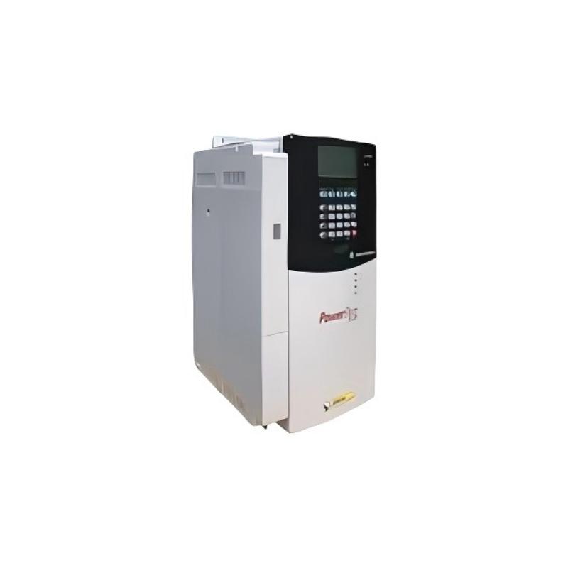
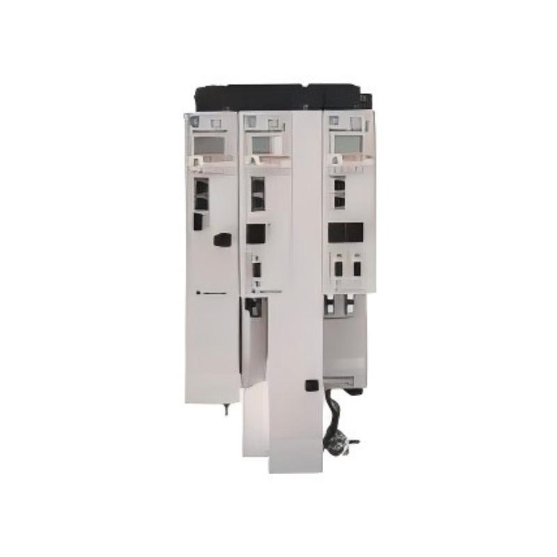
- Allen Bradley
- 20G11JF795JN0NNNNN
- PowerFlex AC Drive
- USA
- 2477 × 1200 × 800 mm
- 1287kg
- Xiamen, China
- New & In Stock
- T/T, PayPal, Western Union
- 1 Year
- 1-3 Working Days
- DHL, UPS, TNT, FedEx and EMS.
- 24-Hour Service
- COO
- 89
Our advantage

Global Logistics
We have a 10-year logistics and express cooperation agreement, so our products can be shipped to any place in the world.

Brand new and original
Our products are imported in bulk from the place of origin. Because of the cooperative relationship, our products are all original and 100% new.

24-hour service
We provide 7*24 hours service to our customers. We will be there whenever you need us.

Price advantage
All our products are priced very favorably because we have our own warehouse and supply.
| Company Information | |||
| [email protected] | |||
| Mobile | +8615980777398 | ||
| +8615980777398 | |||
| 15980777398 |
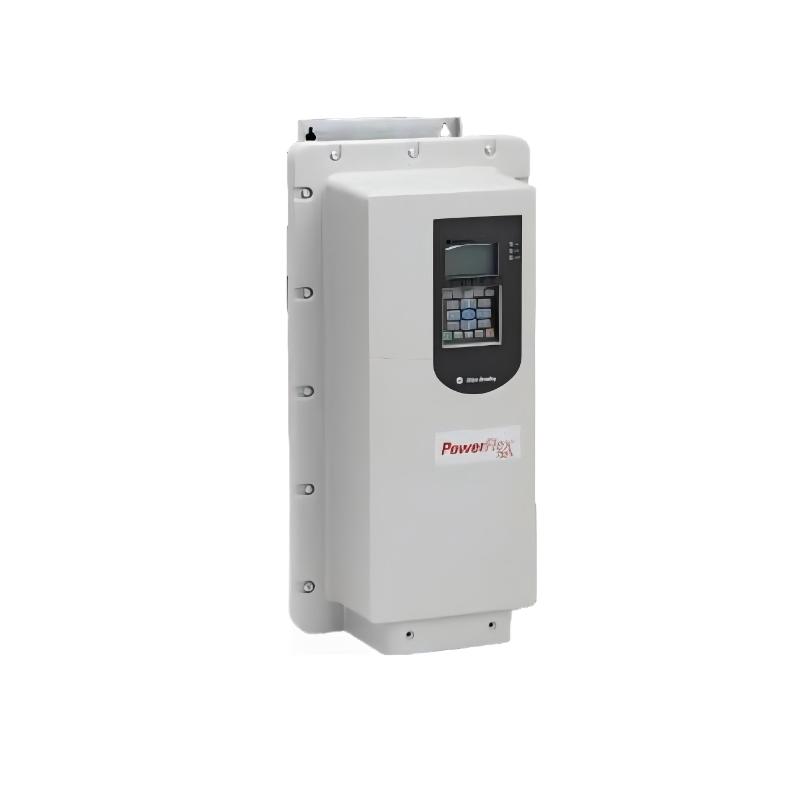
Allen-Bradley 20G11JF795JN0NNNNN PowerFlex 755 AC Drive
1. Product Overview
The 20G11JF795JN0NNNNN is a high-power AC variable-frequency drive from the Allen-Bradley PowerFlex 755 series. It is designed for large industrial motors and demanding variable-speed applications where high output power, reliable motor control, industrial protection, communication capability and flexible application control are required.
This model is a 690 VAC, three-phase, air-cooled PowerFlex 755 AC drive with a rated output current of 795 A. Its principal rating is 800 kW under Normal Duty, while its Heavy Duty rating is approximately 710 kW.
The drive uses a Frame 9 construction and an IP54 / NEMA Type 12 enclosure arrangement. The catalog configuration is an approximately 800 mm deep MCC-style packaged drive, with forced-air cooling, embedded EtherNet/IP communication, AC input with precharge and DC terminals, filtering, CM jumper installed, no internal dynamic-braking transistor and no door-mounted HIM.
The combination of a 795 A current rating and 800 kW Normal Duty rating places this model firmly in the high-power industrial drive category. It is intended for applications such as large pumps, fans, conveyors, material-handling equipment, process machinery, mining equipment, large ventilation systems and other heavy industrial rotating equipment.
The product is not simply a high-current motor inverter. It is designed as part of an industrial automation system, where motor speed, process variables, operating status, alarms and control commands can be exchanged between the drive and the plant control system.
2. Brand and Product Series
| Item | Specification |
|---|---|
| Brand | Allen-Bradley |
| Product Family | PowerFlex |
| Product Series | PowerFlex 755 |
| Product Type | AC Variable Frequency Drive |
| Product Classification | High-power industrial AC drive |
| Model | 20G11JF795JN0NNNNN |
| Cooling | Forced air / air cooled |
| Frame | Frame 9 |
| Enclosure | IP54 / NEMA Type 12 |
| Installation Style | MCC-style packaged drive |
| Voltage Class | 690 VAC |
| Input | Three-phase AC |
| Output Current | 795 A |
| Normal Duty Rating | 800 kW |
| Heavy Duty Rating | 710 kW |
| Communication | Embedded EtherNet/IP |
| Dynamic Braking | No internal dynamic-braking transistor |
| HIM | No door-mounted HIM |
| EMC / Filtering | Filtered |
| CM Jumper | Installed |
| Input Configuration | AC input with precharge and DC terminals |
3. Model Identification
The catalog number 20G11JF795JN0NNNNN contains a number of configuration elements that distinguish this drive from other PowerFlex 755 versions.
The most significant characteristics are the PowerFlex 755 platform, air-cooled construction, 690 VAC voltage class, Frame 9 architecture, 795 A current rating, IP54 / Type 12 enclosure, filtered configuration, CM jumper arrangement, absence of an internal dynamic-braking transistor and absence of a door-mounted HIM.
A simplified interpretation is shown below.
| Configuration | Meaning |
|---|---|
| 20G | PowerFlex 755 family |
| 11 | Packaged-drive configuration |
| JF | 690 VAC / IP54 packaged configuration family |
| 795 | 795 A drive rating |
| J | Filtered configuration with CM jumper installed |
| N | No internal dynamic-braking transistor |
| 0 | No door-mounted HIM |
| NNNNN | Remaining standard configuration positions / factory options |
The complete catalog number should always be used when ordering or replacing the drive because two PowerFlex 755 drives with similar current and power ratings can have different input arrangements, enclosure types, braking configurations, filtering options or control interfaces.
4. Detailed Technical Parameters
| Parameter | Specification |
|---|---|
| Model | 20G11JF795JN0NNNNN |
| Brand | Allen-Bradley |
| Series | PowerFlex 755 |
| Drive Type | AC Variable Frequency Drive |
| Input Voltage | 690 VAC |
| Input Phase | 3 Phase |
| Frequency | 50 / 60 Hz class |
| Output Current | 795 A |
| Normal Duty Power | 800 kW |
| Heavy Duty Power | 710 kW |
| Light Duty Power | Approximately 900 kW class |
| Frame Size | Frame 9 |
| Cooling | Forced Air |
| Enclosure Rating | IP54 |
| Enclosure Type | NEMA / UL Type 12 |
| Construction | MCC-style packaged drive |
| Depth Designation | 800 mm class |
| AC Input | Yes |
| Precharge | Included |
| DC Terminals | Included |
| EMC Filtering | Filtered |
| CM Jumper | Installed |
| Dynamic Braking Transistor | Not included |
| Embedded EtherNet/IP | Yes |
| HIM | No door-mounted HIM |
| PID Control | Available |
| Safety Functions | Supported with appropriate system configuration |
| Operating Environment | Industrial |
| Storage Temperature | Approximately -40°C to +70°C |
| Approx. Overall Dimensions | Approximately 2453 × 1200 × 600 mm in one listed dimensional configuration |
| Enclosure Depth Designation | 800 mm MCC-style class |
| Approx. Weight | Approximately 200 kg as a listed equipment value; verify final configured package |
| Cooling Airflow | Approximately 1,805 m³/h |
| Cooling Fan Type | Backward-curved centrifugal |
| Fan Electrical Input | Approximately 0.45 kW |
| Main Applications | Pumps, fans, conveyors, mining, material handling, process machinery |
| Installation | Industrial electrical room / MCC / appropriately engineered enclosure |
5. Important Note About Dimensions and Weight
The physical size of this drive needs particular attention because it is a Frame 9 high-power packaged drive, rather than a small wall-mounted VFD.
The enclosure is identified as an approximately 800 mm deep MCC-style construction. A dimensional listing for this particular configuration gives approximately 2453 mm height × 1200 mm width × 600 mm depth.
Because packaged high-power drives can have different cabinet and connection arrangements, the dimensional designation and the externally measured cabinet dimensions should not automatically be treated as identical values. For actual panel fabrication, transportation, lifting and installation, the final mechanical drawing for the exact configuration should be used.
For weight, approximately 200 kg is a useful listed reference value for this model, but the final shipping or installed weight can vary depending on the complete package, accessories and cabinet arrangement.
Therefore, for engineering work, the recommended presentation is:
Dimensions: approximately 2453 × 1200 × 600 mm; MCC enclosure depth class approximately 800 mm; weight approximately 200 kg, subject to final configuration.
This is particularly important for a Frame 9 drive because cabinet floor loading, lifting access, door clearance, ventilation and maintenance space all need to be considered before installation.
6. Electrical Rating
The 20G11JF795JN0NNNNN is designed for a 690 VAC three-phase industrial power system.
Its nominal output current is 795 A, making it suitable for very large motors.
The normal-duty rating is approximately 800 kW, while the heavy-duty rating is approximately 710 kW.
This difference is important because motor selection should not be based solely on the motor’s nameplate kW value.
For example, a large fan or centrifugal pump may operate primarily as a variable-torque load and therefore be suitable for a Normal Duty rating.
A crusher, conveyor or other high-inertia machine may require greater overload capability during acceleration. In such a case, the Heavy Duty rating becomes more important.
For this reason, the 800 kW figure should not be interpreted as meaning that every 800 kW motor is automatically suitable for this drive.
7. Normal Duty, Heavy Duty and Light Duty
The PowerFlex 755 family uses different duty classifications to allow the drive to be selected according to the actual load profile.
| Duty Classification | Approx. Rating for 20G11JF795JN0NNNNN | Typical Load |
|---|---|---|
| Light Duty | Approx. 900 kW class | Lower overload / lighter process loads |
| Normal Duty | 800 kW | Pumps, fans and moderate-load applications |
| Heavy Duty | 710 kW | High torque, high inertia and demanding acceleration |
The 800 kW Normal Duty rating is one of the defining characteristics of this model.
The 710 kW Heavy Duty rating is more appropriate when the application requires greater overload performance.
The 900 kW Light Duty class should be treated as a specialized rating and should not be used as a general substitute for the Heavy Duty rating.
The actual motor current, overload profile, acceleration time, inertia and speed range should be checked before final selection.
8. Product Introduction
The PowerFlex 755 is an architecture-level AC drive platform designed for applications where the drive must perform more than simple speed adjustment.
The 20G11JF795JN0NNNNN extends this concept into the high-power range.
With a 795 A current rating and 800 kW Normal Duty capacity, it can control very large motors while remaining part of a modern industrial control network.
The integrated EtherNet/IP interface allows the drive to exchange operating information with the control system.
For example, a controller can provide a speed reference while the drive reports actual speed, current, operating state, warnings and fault information.
This makes the drive particularly useful in automated production lines, process plants and large material-handling systems.
9. Main Product Features
9.1 High-Power Output
The most obvious feature is its high output capacity.
At 795 A, the drive is designed for motors that would be far beyond the range of compact industrial VFDs.
The approximately 800 kW Normal Duty rating makes it suitable for very large rotating equipment.
This allows variable-speed operation to be introduced into large industrial machines that might otherwise rely on fixed-speed motor starters.
9.2 690 VAC Operation
The 690 VAC voltage class is suitable for high-power motor systems.
Using a higher voltage for large motors helps keep current within a practical range for power distribution.
This is especially useful in large factories, mining operations, processing facilities and other industrial environments where many high-power motors may operate simultaneously.
9.3 Embedded EtherNet/IP
The embedded EtherNet/IP function is an important advantage for automation integration.
The drive can participate in a networked control architecture rather than operating as an isolated motor controller.
Typical information may include:
- Start command
- Stop command
- Speed reference
- Actual speed
- Output frequency
- Output current
- Drive status
- Fault status
- Warning status
- Process reference
- Feedback values
9.4 IP54 / Type 12 Construction
The IP54 / NEMA Type 12 arrangement provides a level of protection suitable for many industrial environments.
It is more protective than an open-frame drive and can be used in appropriately designed industrial electrical areas.
The protection rating should not be interpreted as universal protection against every environmental condition. Severe humidity, corrosive gases, conductive dust, salt spray and direct washdown may require additional engineering.
9.5 Forced-Air Cooling
High-power semiconductor equipment generates significant heat.
The 20G11JF795JN0NNNNN therefore uses forced-air cooling.
The cooling arrangement is based on a backward-curved centrifugal fan, with an airflow value of approximately 1,805 m³/h for the referenced configuration.
Adequate airflow is essential.
If ventilation passages are blocked or the surrounding temperature is too high, the drive can operate at elevated temperatures, potentially reducing component life and increasing thermal protection events.
10. Product Applications
10.1 Large Pump Systems
Large pumps are one of the most practical applications for this drive.
A fixed-speed pump often operates at one speed even when process demand changes.
With a variable-speed drive, the motor can operate at a lower speed when full flow is unnecessary.
This can improve process control and may reduce energy consumption.
Typical applications include:
- Industrial water supply
- Cooling-water circulation
- Process water
- Water treatment
- Mining water systems
- Large pumping stations
- Chemical process pumping
- Utility pumping systems
10.2 Large Fans and Blowers
Large fans and blowers can also benefit from variable-speed operation.
Industrial ventilation requirements are rarely constant.
For example, a ventilation system may require full airflow during a production phase but substantially less airflow during standby operation.
The drive can adjust motor speed to match the actual process requirement.
Typical applications include:
- Industrial ventilation
- Furnace exhaust
- Dust collection
- Process air
- Large HVAC systems
- Mine ventilation
- Exhaust systems
- Combustion air systems
10.3 Conveyor Systems
Large conveyors are another important application.
High-power conveyors can have significant inertia, especially when carrying large quantities of material.
The drive can provide controlled acceleration and deceleration.
This can reduce mechanical shock to belts, gearboxes, couplings and drive pulleys.
Typical applications include:
- Mining conveyors
- Cement plants
- Aggregate handling
- Port terminals
- Bulk material handling
- Steel plants
- Warehouse material handling
- Long-distance conveyors
10.4 Mining Equipment
The high power rating makes this model relevant to mining applications.
Possible uses include:
- Ore conveyors
- Large pumps
- Ventilation systems
- Crushers
- Material-processing equipment
- Slurry systems
- Large fans
Mining environments can have additional requirements concerning dust, temperature, hazardous areas and environmental protection. Those requirements must be evaluated separately.
10.5 Metals and Processing Equipment
Large metal-processing equipment often uses motors with substantial power requirements.
Variable-speed control can be useful for controlling:
- Large fans
- Pumps
- Conveyors
- Roll systems
- Material-handling equipment
- Process machinery
The drive’s communication capabilities can also help integrate motor control with the larger production system.
10.6 Oil, Gas and Process Facilities
Large process facilities frequently use pumps, fans and compressors.
Variable-speed control can help match motor output to process demand.
The drive can also provide operating information to the control system, which is useful for plant monitoring and maintenance.
The exact certification and environmental requirements must be evaluated for each installation because process industries can have specialized requirements.
11. Product Advantages
11.1 High Motor Power Capability
The first major advantage is the ability to control very large motors.
The approximately 800 kW Normal Duty rating provides substantial capacity for large industrial equipment.
This makes the product suitable for applications where smaller VFDs cannot provide the required current or power.
11.2 Better Process Control
A fixed-speed motor generally provides one operating speed.
A VFD provides a variable-speed output.
This allows the motor to follow changing process requirements.
For pumps and fans, this can improve pressure and flow regulation.
For conveyors, it can improve material handling.
For process machines, it can allow the operating speed to be coordinated with other equipment.
11.3 Controlled Acceleration
Large motors can create substantial mechanical stress during starting.
The drive can gradually increase motor speed rather than applying full operating conditions immediately.
This can reduce mechanical shock and improve the starting behavior of high-inertia equipment.
11.4 Controlled Deceleration
The same principle applies during stopping.
Controlled deceleration can reduce sudden mechanical loading.
However, because this particular configuration does not include an internal dynamic-braking transistor, applications requiring rapid deceleration or substantial regenerative energy need to be engineered with the appropriate braking or regenerative solution.
11.5 Network Integration
Embedded EtherNet/IP makes the drive suitable for networked automation.
The motor controller can exchange information with the plant control system without requiring the drive to function as a standalone device.
This is particularly useful when many drives are operating as part of one production system.
11.6 Diagnostic Capability
Drive-level monitoring can provide useful information during operation.
Examples include:
- Current
- Frequency
- Speed
- Status
- Warning conditions
- Fault conditions
- Operating state
This can simplify troubleshooting and help maintenance personnel identify abnormal conditions.
11.7 Energy-Saving Potential
The drive can reduce motor speed when the process does not require full output.
This can be particularly valuable for centrifugal pumps and fans.
Actual energy savings depend on the application, motor efficiency, load profile, operating hours and process requirements.
The presence of a VFD alone should therefore not be interpreted as a guaranteed percentage of energy savings.
12. Advantages for Large Pump Applications
A large pump may spend considerable time operating below maximum process demand.
A variable-speed drive allows the pump to respond to the actual requirement instead of operating continuously at full speed.
For example, a process may require high pressure during one production stage and lower pressure during another.
The drive can adjust motor speed accordingly.
The result can be a more flexible pumping system with improved process control and potential electrical-energy savings.
13. Advantages for Large Fan Applications
Fan systems are especially suitable for variable-speed operation because airflow demand frequently changes.
Instead of using mechanical dampers to restrict airflow while keeping the motor near full speed, the drive can reduce motor speed.
This can provide a more direct way of matching motor output to the required airflow.
For large industrial ventilation systems, even a moderate reduction in motor operating speed can produce a meaningful reduction in energy demand, depending on the fan system and operating point.
14. Advantages for Conveyor Applications
Conveyor starting can be mechanically demanding.
A large belt may have significant mass, and the material being transported adds additional inertia.
Controlled acceleration allows the conveyor to reach operating speed gradually.
This can reduce stress on:
- Belts
- Gearboxes
- Couplings
- Shafts
- Bearings
- Drive pulleys
- Mechanical frames
The same control capability can also be used to coordinate multiple conveyor sections.
15. Advantages for Automated Production Lines
A modern production line often requires motors to respond to commands from a central control system.
The drive can receive commands over the industrial network and return operating information.
This makes it possible to build a control architecture in which the drive becomes an active part of the production process.
For example:
PLC / Controller → EtherNet/IP → PowerFlex 755 → Motor → Mechanical Process
The controller can determine the required speed while the drive handles the motor-control function.
16. Installation Requirements
A 795 A, 690 VAC drive requires careful engineering.
Important installation considerations include:
- Incoming voltage
- Motor voltage
- Motor current
- Motor power
- Short-circuit current
- Upstream protection
- Grounding
- Cable size
- Motor cable length
- EMC requirements
- Cabinet ventilation
- Ambient temperature
- Cooling airflow
- Maintenance clearance
- Network architecture
- Safety circuit design
- Braking requirements
- Motor insulation compatibility
- Mechanical support
- Lifting requirements
The equipment should be installed and commissioned by personnel qualified for the relevant high-voltage industrial electrical system.
17. Cooling and Ventilation
Cooling is particularly important for this model.
The drive uses forced-air cooling, and the cooling fan is a backward-curved centrifugal type.
The approximate airflow is 1,805 m³/h.
This means that the installation area must allow sufficient air movement.
The following conditions should be avoided:
- Blocked ventilation openings
- Excessive ambient temperature
- Heavy dust accumulation
- Restricted exhaust airflow
- Poor cabinet ventilation
- Recirculation of hot air
- Installation close to significant heat sources
Cooling performance is directly related to reliability and service life.
18. Dynamic Braking
The catalog configuration 20G11JF795JN0NNNNN does not include an internal dynamic-braking transistor.
This is an important consideration when selecting the drive for high-inertia machinery.
If the motor needs to decelerate rapidly, mechanical energy may return toward the DC bus.
The correct braking solution depends on the application.
Possible system approaches can include an appropriately engineered external braking arrangement or a regenerative solution where the application requires repeated energy return.
Therefore, if the drive is intended for a crane, high-inertia conveyor, rapid-cycle machine or another application requiring frequent fast stopping, braking requirements should be evaluated before selecting this particular configuration.
19. Communication and Automation
The embedded EtherNet/IP interface is one of the strongest features of the PowerFlex 755 platform.
A networked drive can provide both control and diagnostic information.
Typical control data can include:
| Control / Monitoring Item | Typical Function |
|---|---|
| Start | Starts the motor |
| Stop | Stops the motor |
| Speed Reference | Determines target speed |
| Actual Speed | Reports current motor speed |
| Output Frequency | Reports operating frequency |
| Output Current | Indicates motor loading |
| Drive Status | Indicates operating condition |
| Fault Code | Identifies drive fault |
| Warning | Indicates abnormal condition |
| Process Reference | Used for process control |
| Feedback | Used for PID or closed-loop control |
20. PID Process Control
PID control is useful in process applications.
For example, a pump may need to maintain a particular pressure.
The drive can compare the actual feedback value with the desired setpoint and adjust motor speed accordingly.
The same basic concept can be applied to:
- Pressure
- Flow
- Temperature-related process control
- Airflow
- Liquid level
- Other process variables
This allows the motor to respond continuously to process conditions rather than simply running at a fixed speed.
21. Mechanical Installation
The 20G11JF795JN0NNNNN is substantially larger than compact VFDs.
A useful physical reference is approximately:
Height: 2453 mm
Width: 1200 mm
Depth: 600 mm in one listed dimensional configuration
MCC-style enclosure depth class: approximately 800 mm
Weight: approximately 200 kg as a listed reference value
The dimensional information should be considered an engineering reference rather than a replacement for the final mechanical drawing.
The installation should provide sufficient space for:
- Door opening
- Power-cable routing
- Control-cable routing
- Cooling-air circulation
- Maintenance
- Fan replacement
- Inspection
- Safe electrical access
- Equipment lifting and removal
22. Recommended Same-Series Models
The following five models are useful related choices within the PowerFlex 755 family.
They are arranged around the 795 A target model so that the selection can be adjusted according to motor current and required duty.
| Model | Voltage | Current | Normal Duty | Heavy Duty | Frame | Enclosure | Approx. Dimensions | Weight (kg) |
|---|---|---|---|---|---|---|---|---|
| 20G11JF650JN0NNNNN | 690 VAC | 650 A | 710 kW | 500 kW | 9 | IP54 / Type 12 | Approx. 710 × 1200 × 600 mm class* | Configuration-dependent |
| 20G11JF710JN0NNNNN | 690 VAC | 710 A | 800 kW | 590 kW | 9 | IP54 / Type 12 | Approx. 790 × 1200 × 600 mm class* | Configuration-dependent |
| 20G11JF765JN0NNNNN | 690 VAC | 765 A | 750 kW | 630 kW | 9 | IP54 / Type 12 | Approx. 860 × 1200 × 600 mm class* | Configuration-dependent |
| 20G11JF795JN0NNNNN | 690 VAC | 795 A | 800 kW | 710 kW | 9 | IP54 / Type 12 | Approx. 2453 × 1200 × 600 mm** | Approx. 200 |
| 20G11JF960JN0NNNNN | 690 VAC | 960 A | 1000 kW | 800 kW | 10 | IP54 / Type 12 | Configuration-dependent | Configuration-dependent |
* The first dimension shown in the same-series comparison is not intended to replace the complete cabinet dimensional drawing. Frame and cabinet configurations can change the final external dimensions.
** A complete dimensional listing for the target configuration gives approximately 2453 mm height × 1200 mm width × 600 mm depth, while the catalog description identifies an 800 mm-deep MCC-style configuration. Final mechanical documentation should control installation.
23. Same-Series Model Comparison
| Model | Main Difference from Target | Recommended Use |
|---|---|---|
| 20G11JF650JN0NNNNN | Lower 650 A current rating | Large pumps, fans and moderate-power conveyors |
| 20G11JF710JN0NNNNN | Lower 710 A current rating | Applications around the 800 kW Normal Duty class |
| 20G11JF765JN0NNNNN | Slightly lower 765 A current rating | Large 690 VAC motors below the 795 A range |
| 20G11JF795JN0NNNNN | Target 795 A configuration | High-power 690 VAC industrial motors |
| 20G11JF960JN0NNNNN | Higher 960 A current rating | Larger high-power motors and heavier installations |
The 20G11JF710JN0NNNNN and 20G11JF765JN0NNNNN are particularly useful when the required motor current is close to the target model but does not require the full 795 A capacity.
The 20G11JF960JN0NNNNN is more appropriate when the motor current or process power exceeds the practical operating range of the 795 A model.
24. Five Related / Popular Allen-Bradley Models
The following five models are useful examples from the broader Allen-Bradley variable-frequency-drive portfolio. They cover a much wider application range than the 795 A PowerFlex 755.
| Model | Series | Voltage | Output Current | Power Rating | Frame | Enclosure | Braking | Dimensions | Weight (kg) |
|---|---|---|---|---|---|---|---|---|---|
| 25B-D017N114 | PowerFlex 525 | 380–480 VAC, 3 Ph | 17.5 A | 7.5 kW ND / 7.5 kW HD | C | IP20 | Internal brake transistor | Compact Frame C; final dimensions configuration-dependent | Approx. 3–4 |
| 20F11NC043JA0NNNNN | PowerFlex 753 | 400 VAC, 3 Ph | 43 A | 22 kW ND / 18.5 kW HD | 3 | IP20/IP00 | Internal DB transistor | Compact Frame 3; final dimensions configuration-dependent | Approx. 20 |
| 20GE1ND027JA0NNNNN | PowerFlex 755TS | 480 VAC, 3 Ph | 27 A | 20 HP ND / 15 HP HD | 3 | IP20/IP00 | DB transistor | Frame 3; configuration-dependent | Configuration-dependent |
| 20GE1ND096JA0NNNNN | PowerFlex 755TS | 480 VAC, 3 Ph | 96 A | 75 HP ND / 60 HP HD | 5 | IP20/IP00 | DB transistor | Frame 5; configuration-dependent | Configuration-dependent |
| 20G2AND477JA0NNNNN | PowerFlex 755TS | 480 VAC, 3 Ph | 477 A | 400 HP ND / 300 HP HD | 7 | IP20/IP00 | DB transistor | Frame 7; configuration-dependent | Configuration-dependent |
The five models above are not direct substitutes for the 20G11JF795JN0NNNNN.
They represent different points in the product range.
The PowerFlex 525 is more appropriate for compact machine-level applications.
The PowerFlex 753 is aimed at general architecture-level industrial motor control.
The PowerFlex 755TS provides a newer high-performance drive architecture with dual embedded EtherNet/IP and additional control capabilities.
The 795 A PowerFlex 755 remains the more appropriate choice when the application specifically requires a 690 VAC, approximately 800 kW-class industrial drive.
25. PowerFlex 525 — 25B-D017N114
The 25B-D017N114 is a much smaller drive than the 20G11JF795JN0NNNNN.
It is a 380–480 VAC three-phase PowerFlex 525 with an output current of approximately 17.5 A and a power rating around 7.5 kW / 10 HP.
It is suitable for smaller machines, pumps, fans, conveyors and general-purpose motor applications.
Compared with the 795 A PowerFlex 755, its main advantages are compact size, simpler installation and suitability for lower-power machines.
| Parameter | 25B-D017N114 |
|---|---|
| Series | PowerFlex 525 |
| Input | 380–480 VAC |
| Phase | 3 Phase |
| Output Current | Approx. 17.5 A |
| Normal Duty | 7.5 kW |
| Heavy Duty | 7.5 kW |
| Frame | C |
| Enclosure | IP20 |
| EtherNet/IP | Embedded |
| Safety | Integrated safety capability |
| Braking | Internal brake transistor |
| Keypad | Integrated keypad |
| Dimensions | Compact Frame C configuration |
| Weight | Approx. 3–4 kg |
26. PowerFlex 753 — 20F11NC043JA0NNNNN
The 20F11NC043JA0NNNNN is a PowerFlex 753 AC drive.
It is rated for 400 VAC three-phase input, approximately 43 A output current, 22 kW Normal Duty and 18.5 kW Heavy Duty.
This model is much smaller than the target drive but belongs to the same broader 750-series architecture.
Its integrated I/O and dynamic-braking transistor make it useful for general industrial machinery where flexible motor control and local I/O are required.
| Parameter | 20F11NC043JA0NNNNN |
|---|---|
| Series | PowerFlex 753 |
| Input | 400 VAC |
| Phase | 3 Phase |
| Output Current | 43 A |
| Normal Duty | 22 kW |
| Heavy Duty | 18.5 kW |
| Frame | 3 |
| Enclosure | IP20/IP00 |
| Cooling | Forced Air |
| Dynamic Braking | Internal DB transistor |
| DC Terminals | Yes |
| Filtering | Yes |
| CM Jumper | Installed |
| HIM | No door-mounted HIM |
| Dimensions | Frame 3, compact industrial configuration |
| Weight | Approx. 20 kg |
27. PowerFlex 755TS — 20GE1ND027JA0NNNNN
The 20GE1ND027JA0NNNNN represents the PowerFlex 755TS family.
It is a 480 VAC three-phase drive with approximately 27 A output current and a rating of 20 HP Normal Duty / 15 HP Heavy Duty.
The 755TS platform is aimed at higher-performance applications where advanced control, networking and modern drive architecture are important.
| Parameter | 20GE1ND027JA0NNNNN |
|---|---|
| Series | PowerFlex 755TS |
| Input | 480 VAC |
| Phase | 3 Phase |
| Output Current | 27 A |
| Normal Duty | 20 HP |
| Heavy Duty | 15 HP |
| Frame | 3 |
| Enclosure | IP20/IP00 |
| Network | Dual embedded EtherNet/IP |
| Braking | DB transistor |
| Cooling | Air cooled |
| DC Terminals | Included |
| CM Jumper | Installed |
| Dimensions | Frame 3, configuration-dependent |
| Weight | Configuration-dependent |
28. PowerFlex 755TS — 20GE1ND096JA0NNNNN
The 20GE1ND096JA0NNNNN is a larger 755TS model with approximately 96 A output current.
Its approximate rating is 75 HP Normal Duty and 60 HP Heavy Duty.
This makes it appropriate for larger industrial machines than the 27 A model while retaining the 755TS architecture.
| Parameter | 20GE1ND096JA0NNNNN |
|---|---|
| Series | PowerFlex 755TS |
| Input | 480 VAC |
| Phase | 3 Phase |
| Output Current | 96 A |
| Normal Duty | 75 HP |
| Heavy Duty | 60 HP |
| Frame | 5 |
| Enclosure | IP20/IP00 |
| Network | Dual embedded EtherNet/IP |
| Braking | DB transistor |
| Cooling | Air cooled |
| DC Terminals | Included |
| CM Jumper | Installed |
| Dimensions | Frame 5, configuration-dependent |
| Weight | Configuration-dependent |
29. PowerFlex 755TS — 20G2AND477JA0NNNNN
The 20G2AND477JA0NNNNN is a much larger PowerFlex 755TS configuration.
It provides approximately 477 A output current, with a rating of approximately 400 HP Normal Duty and 300 HP Heavy Duty at 480 VAC.
Although its power level is below the 795 A target model, it is useful as a related high-performance drive for large industrial machines.
| Parameter | 20G2AND477JA0NNNNN |
|---|---|
| Series | PowerFlex 755TS |
| Input | 480 VAC |
| Phase | 3 Phase |
| Output Current | 477 A |
| Normal Duty | 400 HP |
| Heavy Duty | 300 HP |
| Frame | 7 |
| Enclosure | IP20/IP00 |
| Network | Dual embedded EtherNet/IP |
| Braking | DB transistor |
| Cooling | Forced Air |
| DC Terminals | No DC terminals in this configuration |
| CM Jumper | Installed |
| Dimensions | Frame 7, configuration-dependent |
| Weight | Configuration-dependent |
30. Target Model vs. Related Products
| Feature | 20G11JF795JN0NNNNN | 20G11JF710JN0NNNNN | 20G11JF765JN0NNNNN | 20G11JF650JN0NNNNN | 20G2AND477JA0NNNNN |
|---|---|---|---|---|---|
| Series | PowerFlex 755 | PowerFlex 755 | PowerFlex 755 | PowerFlex 755 | PowerFlex 755TS |
| Voltage | 690 VAC | 690 VAC | 690 VAC | 690 VAC | 480 VAC |
| Current | 795 A | 710 A | 765 A | 650 A | 477 A |
| Normal Duty | 800 kW | 800 kW | 750 kW | 710 kW | 400 HP |
| Heavy Duty | 710 kW | 590 kW | 630 kW | 500 kW | 300 HP |
| Frame | 9 | 9 | 9 | 9 | 7 |
| Enclosure | IP54 | IP54 | IP54 | IP54 | IP20/IP00 |
| EtherNet/IP | Yes | Yes | Yes | Yes | Dual embedded |
| Dynamic Braking | No internal transistor | No internal transistor | No internal transistor | No internal transistor | DB transistor |
| Cooling | Forced Air | Forced Air | Forced Air | Forced Air | Forced Air |
| Typical Use | Very large motors | Large motors | Large motors | Large motors | High-performance medium/large motors |
31. Advantages of the 20G11JF795JN0NNNNN Over Smaller Drives
The primary advantage is capacity.
A 795 A drive can operate with motor systems that would be far beyond the range of small and medium drives.
Another advantage is the 690 VAC architecture.
For high-power motors, using a higher motor voltage can make the power-distribution design more manageable.
The IP54 / Type 12 construction also makes this configuration more suitable for industrial electrical environments than a basic open-frame VFD.
The embedded EtherNet/IP capability is another major advantage because the drive can be integrated into a plant-wide automation system.
Finally, the PowerFlex 755 architecture provides a broad set of control functions, making the product useful in applications where the drive needs to interact with process-control logic rather than simply generate a variable-frequency output.
32. Limitations and Selection Points
The product is powerful, but it is not automatically the best solution for every application.
Its large physical size can be a disadvantage for small installations.
Its 690 VAC voltage class also means that it cannot simply be substituted into a 400 VAC or 480 VAC system.
The 795 A current rating may also be unnecessarily large for a motor that only requires a few hundred amperes.
The absence of an internal dynamic-braking transistor is another selection consideration for applications with frequent rapid deceleration.
The lack of a door-mounted HIM means that the local operator interface needs to be considered separately if local keypad operation is required.
The forced-air cooling arrangement also means that ventilation and maintenance of the cooling system are important.
33. Recommended Application Matching
| Application | Suitability | Reason |
|---|---|---|
| Large centrifugal pump | Excellent | High power, variable-speed control and PID |
| Large fan | Excellent | Variable speed and energy-management potential |
| Large conveyor | Excellent | Controlled acceleration and speed control |
| Mining conveyor | Excellent | High-power motor control and industrial networking |
| Large ventilation system | Excellent | High power and variable airflow |
| Material handling | Excellent | Speed control and automation integration |
| Crusher | Good | High power, but Heavy Duty and torque requirements must be checked |
| High-inertia machine | Good | Requires careful braking and acceleration analysis |
| Small pump | Poor | Drive is substantially oversized |
| Small fan | Poor | Lower-power drive would be more practical |
| Residential HVAC | Poor | Excessively large industrial architecture |
| Rapid regenerative machine | Requires special evaluation | No internal dynamic-braking transistor |
34. Recommended Selection Procedure
For a new project, the following sequence is recommended.
Step 1 — Determine Motor Voltage
Confirm that the motor is appropriate for a 690 VAC-class drive system.
Step 2 — Determine Motor Current
Motor full-load current is more important than simply comparing kW values.
Step 3 — Determine Load Type
Identify whether the application is:
- Variable torque
- Constant torque
- High inertia
- High overload
- Rapid acceleration
- Rapid deceleration
Step 4 — Select Duty Rating
Determine whether Normal Duty or Heavy Duty is required.
Step 5 — Check Braking
If rapid stopping is required, determine whether an external braking or regenerative solution is needed.
Step 6 — Check Environmental Conditions
Consider:
- Temperature
- Humidity
- Dust
- Corrosive atmosphere
- Altitude
- Ventilation
Step 7 — Check Communications
Determine whether EtherNet/IP integration is required.
Step 8 — Check Mechanical Installation
Verify:
- Height
- Width
- Depth
- Cable-entry space
- Door clearance
- Maintenance access
- Floor loading
- Lifting access
Step 9 — Check Thermal Requirements
Verify that the electrical room or enclosure can provide adequate cooling airflow.
Step 10 — Check Safety Requirements
The machine-level safety architecture should be evaluated independently of the basic motor-control function.
35. Practical Buying and Replacement Considerations
When replacing an existing PowerFlex 755 drive, the replacement should not be selected based only on the number 795 in the catalog number.
The replacement should match or improve the following characteristics:
| Replacement Check | Importance |
|---|---|
| Input voltage | Critical |
| Motor current | Critical |
| Duty classification | Critical |
| Enclosure | High |
| Frame | High |
| Dynamic braking | High |
| DC terminals | High |
| Filtering | High |
| Communication | High |
| HIM configuration | Medium / High |
| Cooling | Critical |
| Mechanical dimensions | Critical |
| Weight | High |
| Motor cable arrangement | High |
| Safety functions | High |
| Existing controller compatibility | High |
36. Overall Technical Assessment
The Allen-Bradley 20G11JF795JN0NNNNN is a high-power PowerFlex 755 AC drive intended for large industrial motor-control systems.
Its most important specifications are:
690 VAC
Three-phase
795 A output
800 kW Normal Duty
710 kW Heavy Duty
Frame 9
IP54 / NEMA Type 12
Forced-air cooling
Embedded EtherNet/IP
AC input with precharge and DC terminals
Filtered configuration
CM jumper installed
No internal dynamic-braking transistor
No door-mounted HIM
The product is especially well suited to large pumps, fans, conveyors, mining equipment, process machinery, material-handling systems and other industrial machines where motor power is measured in hundreds of kilowatts.
37. Final Product Summary
| Category | Final Specification |
|---|---|
| Product Model | 20G11JF795JN0NNNNN |
| Brand | Allen-Bradley |
| Product Series | PowerFlex 755 |
| Product Type | High-Power AC Variable Frequency Drive |
| Input Voltage | 690 VAC |
| Input | 3 Phase |
| Output Current | 795 A |
| Light Duty | Approx. 900 kW class |
| Normal Duty | 800 kW |
| Heavy Duty | 710 kW |
| Frame | 9 |
| Cooling | Forced Air |
| Enclosure | IP54 |
| Enclosure Standard | NEMA / UL Type 12 |
| Construction | MCC-style packaged drive |
| Depth Class | Approximately 800 mm |
| Dimensions | Approx. 2453 × 1200 × 600 mm in a listed dimensional configuration |
| Weight | Approx. 200 kg listed reference value; verify final configuration |
| Communication | Embedded EtherNet/IP |
| Dynamic Braking | No internal braking transistor |
| Filtering | Filtered |
| CM Jumper | Installed |
| Input Type | AC input with precharge and DC terminals |
| HIM | No door-mounted HIM |
| Cooling Airflow | Approx. 1,805 m³/h |
| Main Applications | Pumps, fans, conveyors, mining, process machinery, material handling |
| Main Advantage | High-power motor control with industrial automation integration |
| Main Selection Concern | Duty rating, braking requirement, mechanical dimensions and cooling must be checked carefully |
38. Conclusion
The 20G11JF795JN0NNNNN is a substantial high-power variable-frequency drive designed for industrial applications where a conventional small or medium-size VFD is no longer sufficient.
Its 795 A output capability and 800 kW Normal Duty rating make it suitable for large motors used in pumps, fans, conveyors, mining systems, ventilation equipment, material handling and industrial process machinery.
The 690 VAC architecture is particularly useful for large motor installations because it provides a practical voltage level for high-power industrial equipment.
The PowerFlex 755 platform also gives the drive a strong automation advantage. Embedded EtherNet/IP allows the motor controller to exchange commands, operating values, warnings and fault information with a plant control system.
The IP54 / Type 12 construction adds practical industrial protection, while forced-air cooling allows the drive to handle the thermal requirements associated with its high power rating.
The main point that should be kept in mind is that 795 A and 800 kW do not by themselves determine whether this is the correct drive.
The final selection must consider motor current, motor voltage, duty cycle, overload requirement, acceleration, deceleration, braking, environmental conditions, cooling, communications and mechanical installation.
For applications below the 795 A range, the 20G11JF650JN0NNNNN, 20G11JF710JN0NNNNN and 20G11JF765JN0NNNNN provide useful alternatives within the same PowerFlex 755 family.
For higher-power applications, the 20G11JF960JN0NNNNN is a logical step upward.
For smaller or more general industrial machines, the PowerFlex 525, PowerFlex 753 and PowerFlex 755TS families provide more appropriately sized alternatives.
In practical terms, the 20G11JF795JN0NNNNN can be summarized as a 690 VAC, 795 A, 800 kW-class, Frame 9, IP54 industrial AC drive designed for large motor applications and networked automation systems.
For engineering, procurement and replacement work, the most important rule is to match the complete catalog configuration rather than matching only the current rating. This is especially important for high-power drives because enclosure construction, braking, filtering, DC terminals, communication, cooling and mechanical dimensions can materially affect whether a replacement will actually fit and operate correctly.