

ProductPRODUCT
Featured products








Contact Us
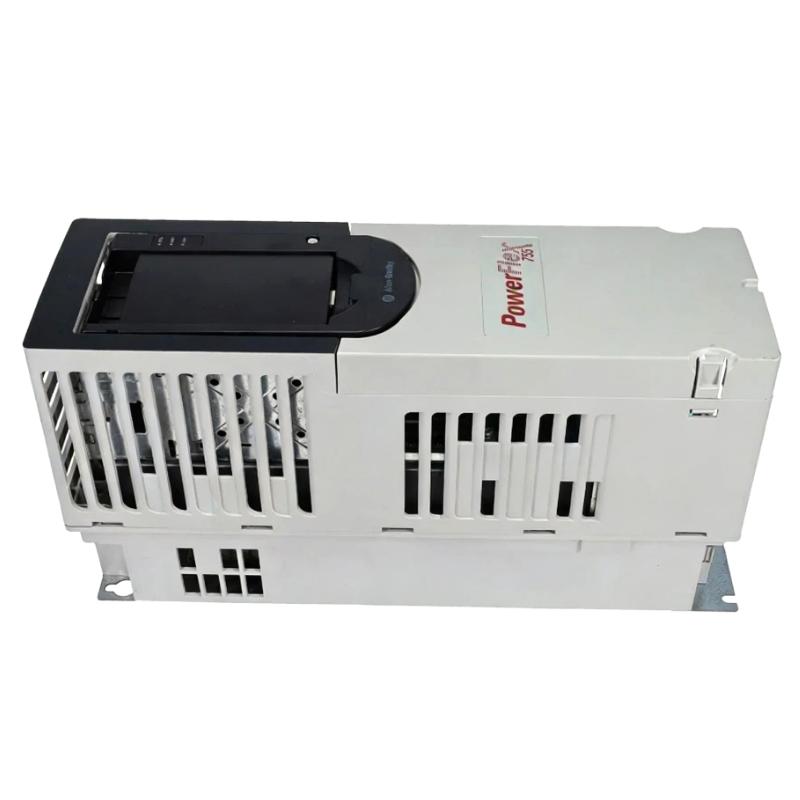
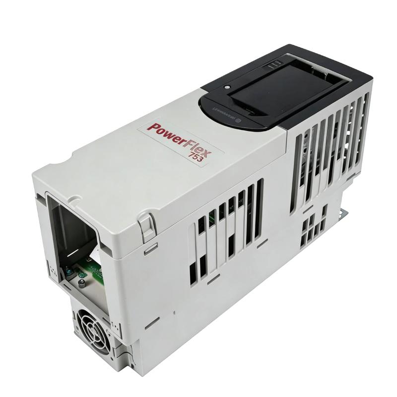
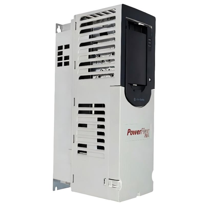
- Allen Bradley
- 20G11FC030JA0NNNNN
- PowerFlex AC Drive
- USA
- 500–560 × 250–270 × 230–260 mm
- 16kg
- Xiamen, China
- New & In Stock
- T/T, PayPal, Western Union
- 1 Year
- 1-3 Working Days
- DHL, UPS, TNT, FedEx and EMS.
- 24-Hour Service
- COO
- 54
Our advantage

Global Logistics
We have a 10-year logistics and express cooperation agreement, so our products can be shipped to any place in the world.

Brand new and original
Our products are imported in bulk from the place of origin. Because of the cooperative relationship, our products are all original and 100% new.

24-hour service
We provide 7*24 hours service to our customers. We will be there whenever you need us.

Price advantage
All our products are priced very favorably because we have our own warehouse and supply.
| Company Information | |||
| [email protected] | |||
| Mobile | +8615980777398 | ||
| +8615980777398 | |||
| 15980777398 |
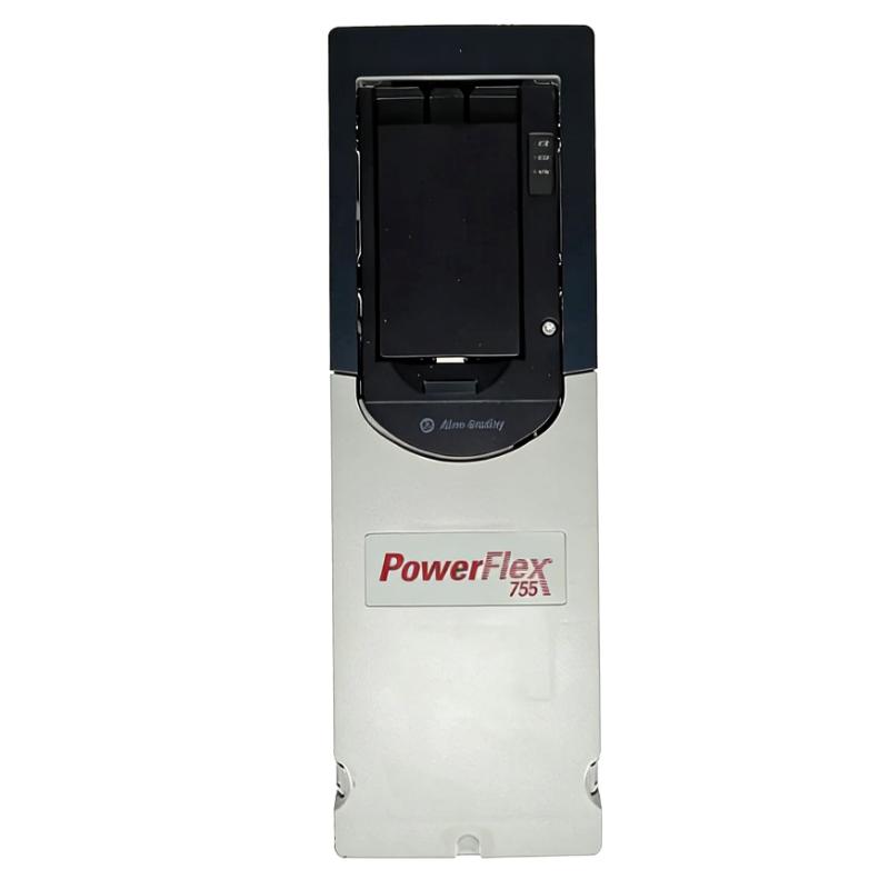
20G11FC030JA0NNNNN — Detailed Product Information, Technical Parameters, Applications, Advantages and Related Models
1. Product Overview
The 20G11FC030JA0NNNNN is an industrial AC variable-frequency drive from the PowerFlex 755 series. It is designed for controlling the speed, torque and operating characteristics of three-phase AC motors in industrial automation and machinery applications.
This model is a 400 VAC, three-phase, 30 A class drive, with a normal-duty power rating of approximately 15 kW. It uses a Frame 3 mechanical configuration and a flange-type installation arrangement.
The drive is intended for applications where adjustable motor speed, controlled acceleration and deceleration, process regulation, network communication and flexible industrial motor control are required.
Typical applications include pumps, fans, conveyors, material-handling systems, processing machinery, mixers, production equipment and other industrial machines that fall within the drive’s electrical and thermal ratings.
The 20G11FC030JA0NNNNN is also a logical step up from the smaller 11 kW class configuration. It provides additional current capacity while retaining the same general PowerFlex 755 platform and industrial-control concept.
2. Brand and Product Series
| Item | Specification |
|---|---|
| Model | 20G11FC030JA0NNNNN |
| Brand | Allen-Bradley |
| Product Family | PowerFlex 750-Series |
| Product Series | PowerFlex 755 |
| Product Type | AC Variable Frequency Drive |
| Drive Type | Industrial AC Drive |
| Mounting Type | Flange Mount |
| Cooling | Forced Air |
| Frame Size | Frame 3 |
| Input Voltage | 400 VAC |
| Input Phase | Three Phase |
| Normal-Duty Current | Approximately 30 A |
| Normal-Duty Power | Approximately 15 kW |
| Heavy-Duty Power Class | Approximately 11 kW |
| Dynamic Braking | Internal Braking Transistor |
| Communication | Embedded EtherNet/IP |
| Input Arrangement | AC Input with Precharge |
| DC Terminals | Yes |
| EMC Configuration | Filtered |
| CM Jumper | Installed |
| HIM Configuration | Blank / No HIM |
| Front Protection | IP20 |
| Mounting Orientation | Vertical |
| Cooling Method | Air Cooled |
3. Basic Technical Parameters
| Parameter | Specification |
|---|---|
| Catalog Number | 20G11FC030JA0NNNNN |
| Product Family | PowerFlex 750-Series |
| Product Series | PowerFlex 755 |
| Product Type | Variable Frequency AC Drive |
| Input Voltage | 400 VAC class |
| Input Phase | 3 Phase |
| Input Frequency | 50/60 Hz |
| Normal-Duty Output Current | Approximately 30 A |
| Normal-Duty Power | Approximately 15 kW |
| Heavy-Duty Power | Approximately 11 kW |
| Normal-Duty Horsepower | Approximately 20 HP |
| Heavy-Duty Horsepower | Approximately 15 HP |
| Frame Size | Frame 3 |
| Cooling | Forced Air |
| Mounting | Flange Mount |
| Dynamic Braking | Internal DB Transistor |
| Input Precharge | Yes |
| DC Bus Terminals | Yes |
| EMC Filter | Filtered Configuration |
| CM Jumper | Installed |
| Communication | Embedded EtherNet/IP |
| HIM | Blank / No HIM |
| Front Enclosure Rating | IP20 |
| Control Architecture | Digital AC Drive |
| Motor Type | Three-Phase AC Motor |
| Process Control | PID Capability |
| Approx. Dimensions | Frame 3 configuration; approximately 500–560 × 250–270 × 230–260 mm, depending on exact mechanical configuration |
| Approx. Weight | Approximately 12–16 kg, depending on exact configuration |
| Installation | Vertical |
| Main Function | Variable-Speed Motor Control |
Important: The physical dimensions and weight of this particular Frame 3 configuration can vary with the exact mechanical arrangement and option configuration. For engineering drawings, panel fabrication or replacement work, the exact mechanical drawing should be checked before the cabinet cutout is finalized.
4. Product Introduction
The 20G11FC030JA0NNNNN is designed to regulate the operating speed of three-phase AC motors.
In a conventional fixed-speed motor system, the motor is connected to a fixed-frequency electrical supply and normally operates close to its designed speed.
A variable-frequency drive provides much greater flexibility.
The drive controls the electrical conditions delivered to the motor, allowing the motor to accelerate, operate and decelerate according to the requirements of the machine.
This makes the drive suitable for processes where motor speed needs to change during production.
For example, a conveyor may need a slow speed during loading and a higher speed during normal transportation.
A pump may need different speeds depending on flow or pressure requirements.
A fan may need to adjust its speed according to ventilation demand.
A mixer may need different speeds during different stages of the production process.
The 20G11FC030JA0NNNNN provides the electrical and control platform required for these types of applications.
5. Electrical Rating
The most important electrical characteristic of this model is its approximately 30 A normal-duty output rating.
This places it above the 22 A / 11 kW class model and makes it appropriate for motors in approximately the 15 kW normal-duty range, depending on the actual motor nameplate current and application duty.
The drive should not be selected solely because the motor is labeled “15 kW.”
Motor current is an especially important selection parameter.
Two motors with the same nominal power can have different rated currents depending on their voltage, efficiency, power factor and construction.
Therefore, when selecting this drive, the motor’s actual nameplate current should be compared with the drive’s applicable output-current rating.
6. Normal-Duty and Heavy-Duty Operation
| Operating Category | Approx. Rating | Typical Application |
|---|---|---|
| Normal Duty | 30 A / 15 kW | Pumps, fans, conveyors and general machinery |
| Heavy Duty | Approx. 22 A / 11 kW class | Higher-torque and more demanding loads |
| Input Supply | 400 VAC | Three-phase industrial supply |
| Input Frequency | 50/60 Hz | Industrial power systems |
The normal-duty rating is generally suitable for applications where the motor load is relatively predictable and the overload requirement is moderate.
Heavy-duty operation is more relevant to machines that require greater torque or experience more severe acceleration and overload conditions.
When a machine has high starting torque, repeated acceleration, high inertia or frequent stopping, the heavy-duty rating should be considered carefully.
7. Frame 3 Construction
The 20G11FC030JA0NNNNN uses a Frame 3 construction.
Compared with smaller Frame 1 and Frame 2 drives, Frame 3 provides additional electrical capacity while maintaining a relatively compact industrial form factor.
The Frame 3 design is particularly useful for applications where an 11 kW class drive is too small but a substantially larger drive would be unnecessary.
This makes the model attractive for medium-power industrial machinery.
The frame size also affects:
- Cabinet space
- Cooling requirements
- Mounting arrangement
- Weight
- Cable routing
- Service access
- Thermal management
When designing a panel, the complete mechanical envelope should therefore be considered rather than only the drive’s electrical rating.
8. Dimensions and Weight
Because the model uses a Frame 3 configuration, its mechanical envelope is larger than the smaller 20G11FC022JA0NNNNN Frame 2 configuration.
| Physical Parameter | Approximate Specification |
|---|---|
| Height | Approximately 500–560 mm |
| Width | Approximately 250–270 mm |
| Depth | Approximately 230–260 mm |
| Overall Dimensions | Approximately 500–560 × 250–270 × 230–260 mm |
| Weight | Approximately 12–16 kg |
| Frame | Frame 3 |
| Mounting | Flange Mount |
| Cooling | Forced Air |
| Installation | Vertical |
The dimensions and weight above should be treated as engineering-level approximate values, not as final cabinet-fabrication dimensions.
The actual installation should use the mechanical drawing associated with the complete catalog configuration, particularly when the drive is being installed as a direct replacement.
9. Flange-Mount Configuration
The flange mounting arrangement is one of the important features of this model.
In a conventional installation, the complete drive is positioned inside the electrical cabinet.
With flange mounting, the mounting surface can separate the power section from the control-cabinet interior.
This provides an alternative method of managing heat.
The heat-producing section can be positioned toward the external side of the enclosure while the control portion remains within the protected cabinet space.
For machine builders, this can provide several advantages.
Improved Thermal Management
The power section of an AC drive produces heat during operation.
Flange mounting can help keep a portion of that heat outside the main control enclosure.
Better Cabinet Utilization
The arrangement can make it easier to allocate space to controllers, terminal blocks, contactors, relays and other components.
Flexible Machine Integration
The drive can be integrated into custom machinery where cabinet space is limited.
10. Cooling System
The drive uses forced-air cooling.
The cooling system is important because power electronics generate heat during operation.
Heat generation increases with factors such as:
- Output current
- Ambient temperature
- Switching conditions
- Motor load
- Operating duty
- Installation environment
Adequate airflow should therefore be maintained around the cooling system.
Dust and debris should also be prevented from accumulating around cooling passages.
For long-term reliability, the installation environment should remain within the applicable temperature and humidity limits.
11. Dynamic Braking
The 20G11FC030JA0NNNNN includes an internal dynamic-braking transistor.
This feature is useful for applications where the motor needs to decelerate more quickly or where the load contains significant stored mechanical energy.
During deceleration, energy can be returned from the motor to the drive’s DC bus.
If the DC-bus voltage rises sufficiently, the drive can use the braking circuit to direct energy toward an external braking resistor.
Typical applications include:
- Conveyors
- Material-handling equipment
- Rollers
- Machine tools
- Cutting machinery
- High-inertia equipment
- Positioning equipment
- Production machinery requiring frequent stopping
The braking resistor must be selected according to the actual braking energy, resistance requirements and duty cycle.
12. Embedded EtherNet/IP Communication
The model includes an embedded EtherNet/IP communication interface.
This allows the drive to become part of a networked automation system.
Instead of using the drive as an isolated motor controller, a controller can communicate with it and exchange operating information.
Typical information can include:
| Information | Function |
|---|---|
| Start command | Initiates motor operation |
| Stop command | Stops motor operation |
| Speed reference | Sets desired motor speed |
| Actual speed | Provides operating feedback |
| Output current | Monitors motor loading |
| Drive status | Shows operating condition |
| Fault information | Indicates abnormal conditions |
| Alarm information | Provides warning information |
| Torque information | Supports load monitoring |
| Diagnostic data | Helps maintenance |
| Parameter information | Supports configuration |
This communication capability can be particularly useful in automated production lines where multiple drives need to operate under coordinated control.
13. PID Control Capability
PID control is useful in process applications where a measured variable needs to be maintained around a target value.
Typical examples include:
- Pump pressure
- Flow control
- Air pressure
- Ventilation
- Cooling systems
- Process circulation
For example, if the drive controls a pump maintaining a pressure setpoint, the motor speed can be increased when pressure falls and reduced when pressure rises.
This allows the drive to participate directly in process regulation.
14. Product Applications
14.1 Pump Applications
The 20G11FC030JA0NNNNN is well suited to medium-size industrial pump applications.
Potential applications include:
- Water circulation
- Cooling-water systems
- Process pumps
- Booster pumps
- Industrial fluid handling
- Water-treatment systems
- Cooling systems
- Pressure-control systems
The variable-speed function allows the motor to operate according to the actual process requirement.
This can provide smoother operation compared with repeatedly switching a fixed-speed motor on and off.
15. Fan and Blower Applications
Fans and blowers are another common application area.
The drive can be used in:
- Industrial ventilation
- Exhaust systems
- Factory ventilation
- Cooling systems
- Dust collection
- Air-handling equipment
- Furnace ventilation
- Equipment cooling
The motor speed can be adjusted according to airflow requirements.
This can also reduce unnecessary operation at maximum speed when the process does not require full airflow.
16. Conveyor Applications
The 20G11FC030JA0NNNNN is suitable for many medium-size conveyor systems.
Examples include:
- Production conveyors
- Packaging conveyors
- Assembly conveyors
- Roller conveyors
- Material-transfer systems
- Warehouse conveyors
- Processing lines
The drive can provide controlled acceleration and deceleration.
This can help reduce sudden mechanical stress on belts, gearboxes, couplings and rollers.
Dynamic braking is also useful when the conveyor needs controlled stopping.
17. Packaging Machinery
Packaging machinery frequently requires controlled speed.
The drive can be used for:
- Feed conveyors
- Rollers
- Material handling
- Product positioning
- Packaging lines
- Transfer systems
- Wrapping equipment
The network communication capability can allow the drive to exchange speed and status information with the machine-control system.
18. Mixer and Agitator Applications
Mixers and agitators often need different motor speeds depending on the production process.
The drive can provide:
- Adjustable speed
- Controlled acceleration
- Controlled deceleration
- Process regulation
- Network control
- Motor monitoring
For example, a mixer may operate slowly during material loading, increase speed during mixing and then reduce speed during discharge.
The drive can accommodate this type of operating sequence when correctly programmed.
19. Material-Handling Equipment
Material-handling machinery can benefit from precise speed control.
Potential applications include:
- Feed systems
- Transfer mechanisms
- Roller systems
- Small lifting-related machinery
- Production-line material handling
- Automated transportation equipment
The dynamic-braking capability can be valuable when the load needs to decelerate quickly.
20. Machine Tools and Processing Equipment
The drive can also be used in various processing machines.
Potential applications include:
- Rollers
- Cutting machinery
- Grinding equipment
- Processing equipment
- Machine tools
- Production machinery
- Auxiliary machine drives
The exact suitability depends on motor speed, torque, overload and braking requirements.
21. Product Advantages
| Advantage | Practical Benefit |
|---|---|
| 30 A class output | Suitable for medium-power industrial motors |
| 15 kW normal-duty capacity | Covers applications above the 11 kW class |
| Approx. 11 kW heavy-duty capacity | Supports more demanding load conditions |
| 400 VAC three-phase | Suitable for common industrial systems |
| Frame 3 | Provides greater capacity than smaller frames |
| Flange mounting | Helps with cabinet thermal management |
| Forced-air cooling | Supports continuous industrial operation |
| Dynamic-braking transistor | Provides controlled deceleration capability |
| Embedded EtherNet/IP | Supports networked automation |
| PID control | Useful for process applications |
| Filtered configuration | Helps manage EMC considerations |
| Industrial construction | Suitable for demanding machinery |
| Flexible control architecture | Supports a wide range of applications |
22. Main Advantage Compared with the 11 kW Class Model
One of the most obvious reasons to select the 20G11FC030JA0NNNNN instead of a smaller 11 kW class model is its greater output-current capability.
The approximate comparison is:
| Parameter | 20G11FC022JA0NNNNN | 20G11FC030JA0NNNNN |
|---|---|---|
| Frame | Frame 2 | Frame 3 |
| Normal-Duty Current | 22 A | Approximately 30 A |
| Normal-Duty Power | 11 kW | Approximately 15 kW |
| Heavy-Duty Power | Approximately 7.5 kW | Approximately 11 kW |
| Mounting | Flange | Flange |
| Cooling | Forced Air | Forced Air |
| Dynamic Braking | Yes | Yes |
| Network Communication | Embedded EtherNet/IP | Embedded EtherNet/IP |
| Physical Size | Smaller | Larger |
| Weight | Approximately 8 kg | Approximately 12–16 kg |
The 30 A class model therefore provides a useful increase in motor capacity.
The trade-off is that the Frame 3 drive requires more cabinet space and has a greater physical weight.
23. Why Choose the 20G11FC030JA0NNNNN?
This model is particularly attractive when an application is too demanding for a smaller 11 kW drive but does not justify moving to a much larger power class.
It offers a balanced combination of:
- Medium-power output
- Industrial networking
- Dynamic braking
- Flange mounting
- Process control
- Forced-air cooling
- Flexible installation
- Industrial motor-control functions
For machine builders, this makes it a practical option for medium-size automated machinery.
24. Five Recommended Same-Series or Closely Related Models
The following models are useful comparison choices within the same product family.
| Model | Series | Voltage Class | Normal-Duty Current | Normal-Duty Power | Heavy-Duty Power | Frame | Approx. Dimensions | Approx. Weight |
|---|---|---|---|---|---|---|---|---|
| 20G11FC022JA0NNNNN | PowerFlex 755 | 400 V | 22 A | 11 kW | 7.5 kW | 2 | 481.8 × 206.2 × 212 mm | 8 kg |
| 20G11FC030JA0NNNNN | PowerFlex 755 | 400 V | Approx. 30 A | 15 kW | Approx. 11 kW | 3 | Approx. 500–560 × 250–270 × 230–260 mm | Approx. 12–16 kg |
| 20G11FC037JA0NNNNN | PowerFlex 755 | 400 V | Approx. 37 A | 18.5 kW | Approx. 15 kW | 3 | Frame 3 class | Approx. 12–16 kg |
| 20G11FC043JA0NNNNN | PowerFlex 755 | 400 V | Approx. 43 A | 22 kW | Approx. 18.5 kW | 3 | Frame 3 class | Approx. 12–16 kg |
| 20G11FC052JA0NNNNN | PowerFlex 755 | 400 V | Approx. 52 A | 30 kW class | Higher-power duty | Larger frame | Larger Frame configuration | Higher than Frame 3 |
Among these choices, the 20G11FC022JA0NNNNN is the closest lower-power alternative, while the 20G11FC037JA0NNNNN and 20G11FC043JA0NNNNN provide additional capacity for larger motors.
The larger models should be considered when the motor current, torque or overload requirement exceeds the capability of the 30 A class drive.
25. Five Related Models — Quick Selection Table
| Model | Approx. Normal-Duty Power | Approx. Current Class | Recommended Use |
|---|---|---|---|
| 20G11FC022JA0NNNNN | 11 kW | 22 A | Smaller pumps, fans and machinery |
| 20G11FC030JA0NNNNN | 15 kW | 30 A | Medium industrial machinery |
| 20G11FC037JA0NNNNN | 18.5 kW | 37 A | Larger conveyors, pumps and fans |
| 20G11FC043JA0NNNNN | 22 kW | 43 A | Higher-capacity industrial machinery |
| 20G11FC052JA0NNNNN | Around 30 kW class | 50 A class | Larger industrial applications |
26. Five Popular Models From the Same Brand
The following are useful models from the same brand’s broader industrial-drive portfolio.
| Model | Product Series | Voltage Class | Approx. Power / Current Class | Typical Application | Cooling | Approx. Dimensions | Approx. Weight |
|---|---|---|---|---|---|---|---|
| 25B-D017N104 | PowerFlex 525 | 400/480 V class | 17 A class | Pumps, fans, conveyors and general machinery | Air cooled | Compact frame | Approx. 5 kg |
| 25B-D024N104 | PowerFlex 525 | 400/480 V class | 24 A class | General industrial machinery | Air cooled | Compact/medium frame | Approx. 6–8 kg |
| 20F11NC030JA0NNNNN | PowerFlex 753 | 400/480 V class | 30 A class | Pumps, fans and conveyors | Air cooled | Frame dependent | Configuration dependent |
| 20G11FC022JA0NNNNN | PowerFlex 755 | 400 V | 22 A | Pumps, fans and general machinery | Air cooled | 481.8 × 206.2 × 212 mm | 8 kg |
| 20G11FC030JA0NNNNN | PowerFlex 755 | 400 V | 30 A | Medium industrial machinery | Air cooled | Frame 3 class | Approx. 12–16 kg |
These models are not all direct substitutes.
The PowerFlex 525 models are generally more suitable where compact size and general-purpose motor control are the main priorities.
The PowerFlex 753 family is appropriate for industrial applications requiring a broader control platform.
The PowerFlex 755 family is better suited to applications where advanced drive functionality, networking, configurable options and industrial integration are important.
27. Comparison With Other Drive Classes
| Feature | Compact General-Purpose Drive | PowerFlex 753 Class | 20G11FC030JA0NNNNN |
|---|---|---|---|
| Target Application | General machinery | Industrial machinery | Medium industrial machinery |
| Power Range | Small to medium | Medium to large | Approximately 15 kW |
| Network Capability | Model dependent | Advanced | Embedded EtherNet/IP |
| Dynamic Braking | Model dependent | Available | Internal braking transistor |
| PID | Available | Available | Available |
| Flange Mounting | Model dependent | Available | Yes |
| Industrial Integration | Moderate | High | High |
| Cabinet Requirements | Smaller | Larger | Medium |
| Physical Weight | Lower | Higher | Approximately 12–16 kg |
28. Applications Where This Model Is Particularly Suitable
| Application | Suitability | Main Reason |
|---|---|---|
| Water Pump | Excellent | Variable-speed control |
| Cooling Pump | Excellent | Adjustable flow and pressure |
| Industrial Fan | Excellent | Adjustable airflow |
| Exhaust Fan | Excellent | Speed regulation |
| Medium Conveyor | Excellent | Controlled acceleration and braking |
| Packaging Equipment | Very Good | Network integration and speed control |
| Material Handling | Very Good | Adjustable speed and deceleration |
| Mixer | Very Good | Variable process speed |
| Agitator | Very Good | Adjustable motor operation |
| Roller Equipment | Very Good | Speed control |
| Processing Machine | Good | Flexible motor control |
| Machine Tool | Good | Controlled motor speed |
| Large Crusher | Limited | May require higher overload capacity |
| Large Mining Conveyor | Limited | Usually requires substantially more power |
| Large Compressor | Application dependent | Torque and overload must be checked |
29. Cabinet Design Considerations
The physical size of the Frame 3 drive should be considered during cabinet design.
The designer should allow space for:
- Drive installation
- Cable entry
- Power connections
- Motor connections
- Grounding
- Cooling airflow
- Service access
- Network connections
- Control wiring
- Braking components
- Maintenance
Flange mounting can provide additional flexibility because the power section can be arranged through the cabinet wall.
However, the exact mounting cutout should always be based on the appropriate mechanical drawing for the specific catalog configuration.
30. Motor Selection Considerations
The drive is intended for three-phase AC motors.
When matching the motor to this model, check:
| Motor Parameter | Why It Matters |
|---|---|
| Rated Voltage | Must match the drive output range |
| Rated Current | Critical for drive sizing |
| Rated Power | Determines approximate drive class |
| Frequency | Determines operating range |
| Rated Speed | Important for speed control |
| Power Factor | Affects current |
| Efficiency | Affects actual motor loading |
| Starting Torque | Important for demanding machinery |
| Continuous Torque | Important for constant-torque applications |
| Overload Requirement | Determines duty classification |
| Inertia | Important for acceleration/deceleration |
| Braking Requirement | Determines braking-system design |
31. Product Advantages for Pumps
For pump applications, the main advantages are adjustable speed and process integration.
The motor does not have to run continuously at a single fixed speed.
The drive can adjust speed according to process requirements.
This is useful in:
- Pressure-control systems
- Water circulation
- Cooling systems
- Process-fluid systems
- Booster systems
The integrated control functions also make the drive suitable for systems where pressure or flow feedback is used.
32. Product Advantages for Fans
For fans, variable-speed control allows the airflow to follow actual demand.
This can be useful in:
- Factory ventilation
- Cooling
- Exhaust
- Air handling
- Dust extraction
The ability to start and stop the motor gradually can also reduce mechanical shock.
33. Product Advantages for Conveyors
For conveyors, controlled acceleration and deceleration can improve the overall mechanical behavior of the machine.
The drive can reduce abrupt changes in motor torque.
This can help protect:
- Belts
- Couplings
- Gearboxes
- Bearings
- Rollers
- Mechanical transmission components
When a rapid stop is necessary, the dynamic-braking capability provides additional flexibility.
34. Product Advantages for Automated Machinery
For automated equipment, the embedded network communication capability is particularly useful.
The drive can become an integrated part of the machine rather than a separate motor-control device.
The controller can send commands and receive operating information.
This makes it easier to implement:
- Automatic speed control
- Machine sequencing
- Alarm monitoring
- Fault handling
- Production monitoring
- Remote diagnostics
- Process control
35. Maintenance and Reliability
The drive should be installed in an environment appropriate for industrial electronic equipment.
Regular inspection should include:
- Cooling airflow
- Cooling fan condition
- Electrical connections
- Grounding
- Motor cables
- Cabinet ventilation
- Dust accumulation
- Drive alarms
- Communication status
- Braking components
- Mounting hardware
Excessive dust, high ambient temperature and poor airflow can increase thermal stress.
Keeping the cooling system clean and maintaining proper electrical connections are therefore important for long-term reliability.
36. Important Selection Notes
The 20G11FC030JA0NNNNN should be selected based on the actual application rather than simply choosing the same kW rating as the motor.
The most important checks are:
- Motor voltage.
- Motor nameplate current.
- Normal-duty or heavy-duty operation.
- Required starting torque.
- Required overload capacity.
- Acceleration time.
- Deceleration time.
- Load inertia.
- Braking requirements.
- Ambient temperature.
- Cabinet cooling.
- Motor cable length.
- Communication requirements.
- Physical dimensions.
- Mounting requirements.
37. Complete Parameter Summary
| Category | Specification |
|---|---|
| Model | 20G11FC030JA0NNNNN |
| Brand | Allen-Bradley |
| Product Family | PowerFlex 750-Series |
| Product Series | PowerFlex 755 |
| Product Type | AC Variable Frequency Drive |
| Input Voltage | 400 VAC class |
| Input Phase | 3 Phase |
| Input Frequency | 50/60 Hz |
| Normal-Duty Current | Approximately 30 A |
| Normal-Duty Power | Approximately 15 kW |
| Heavy-Duty Power | Approximately 11 kW |
| Normal-Duty HP | Approximately 20 HP |
| Heavy-Duty HP | Approximately 15 HP |
| Frame Size | Frame 3 |
| Mounting Type | Flange |
| Cooling | Forced Air |
| Dynamic Braking | Internal DB Transistor |
| Input Precharge | Yes |
| DC Terminals | Yes |
| EMC Filter | Filtered |
| CM Jumper | Installed |
| Embedded EtherNet/IP | Yes |
| PID Control | Yes |
| HIM | Blank / No HIM |
| Front Protection | IP20 |
| Approx. Height | 500–560 mm class |
| Approx. Width | 250–270 mm class |
| Approx. Depth | 230–260 mm class |
| Approx. Dimensions | 500–560 × 250–270 × 230–260 mm |
| Approx. Weight | 12–16 kg |
| Installation | Vertical |
| Motor Type | Three-Phase AC Motor |
| Main Applications | Pumps, fans, conveyors, mixers, packaging and industrial machinery |
38. Final Product Evaluation
The 20G11FC030JA0NNNNN is a medium-power PowerFlex 755 AC drive designed for industrial three-phase motor control.
Its approximately 30 A normal-duty output capacity and 15 kW normal-duty power class make it a suitable choice for applications that require more capacity than an 11 kW class drive can provide.
The Frame 3 construction gives the product additional electrical capacity while maintaining a practical form factor for industrial machinery.
The flange-mount design is particularly useful for machine builders because it can provide more flexibility in cabinet thermal management.
The embedded EtherNet/IP capability is another major advantage for automated machinery.
It allows the drive to communicate with the machine’s control architecture and provides access to operating status, speed references, actual values, alarms and diagnostic information.
The internal dynamic-braking transistor is useful for machinery requiring controlled deceleration.
This makes the drive especially attractive for conveyors, rollers, material-handling equipment and other applications where stopping performance is important.
The product’s main strengths can therefore be summarized as:
- Approximately 15 kW normal-duty capacity
- Approximately 30 A output-current class
- 400 VAC three-phase operation
- Frame 3 construction
- Flange mounting
- Forced-air cooling
- Internal dynamic-braking transistor
- Embedded EtherNet/IP communication
- PID process-control capability
- Filtered configuration
- Industrial machine integration
- Suitable for pumps, fans, conveyors and general machinery
For a new installation, the drive should be matched to the actual motor nameplate current and load characteristics.
For replacement work, the complete catalog number should be matched carefully, because apparently similar models can differ in mounting, filtering, braking, communication, enclosure and other configuration details.
The physical dimensions and weight given above should be regarded as approximate Frame 3 values for planning purposes. For final panel fabrication, use the exact mechanical dimensions applicable to the complete 20G11FC030JA0NNNNN configuration.