

ProductPRODUCT
Featured products



Contact Us
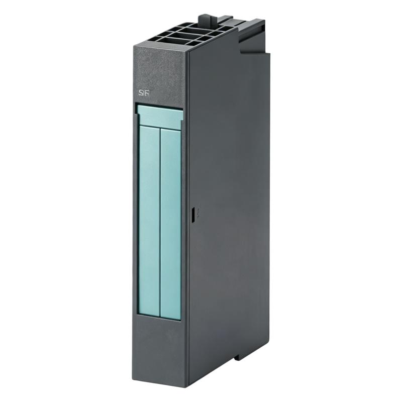
- Siemens
- 6AG1134-4FB01-2AB0
- Analog Input Module
- Germany
- 15 × 81 × 52 mm
- 0.04 kg
- Xiamen, China
- New & In Stock
- T/T, PayPal, Western Union
- 1 Year
- 1-3 Working Days
- DHL, UPS, TNT, FedEx and EMS.
- 24-Hour Service
- COO
- 80
Our advantage

Global Logistics
We have a 10-year logistics and express cooperation agreement, so our products can be shipped to any place in the world.

Brand new and original
Our products are imported in bulk from the place of origin. Because of the cooperative relationship, our products are all original and 100% new.

24-hour service
We provide 7*24 hours service to our customers. We will be there whenever you need us.

Price advantage
All our products are priced very favorably because we have our own warehouse and supply.
| Company Information | |||
| [email protected] | |||
| Mobile | +8615980777398 | ||
| +8615980777398 | |||
| 15980777398 |
Product Overview
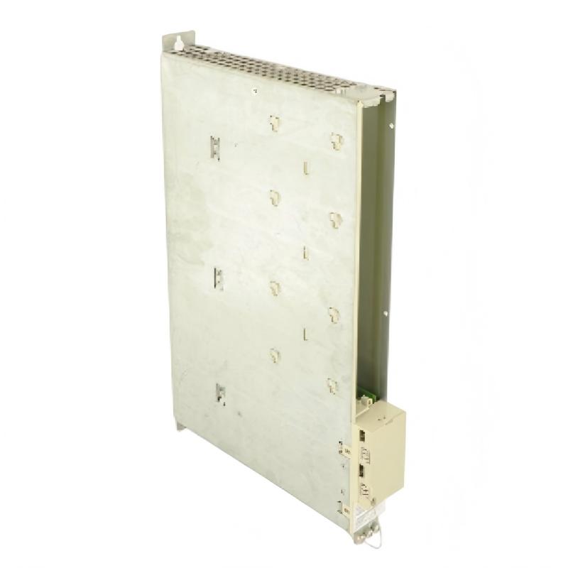
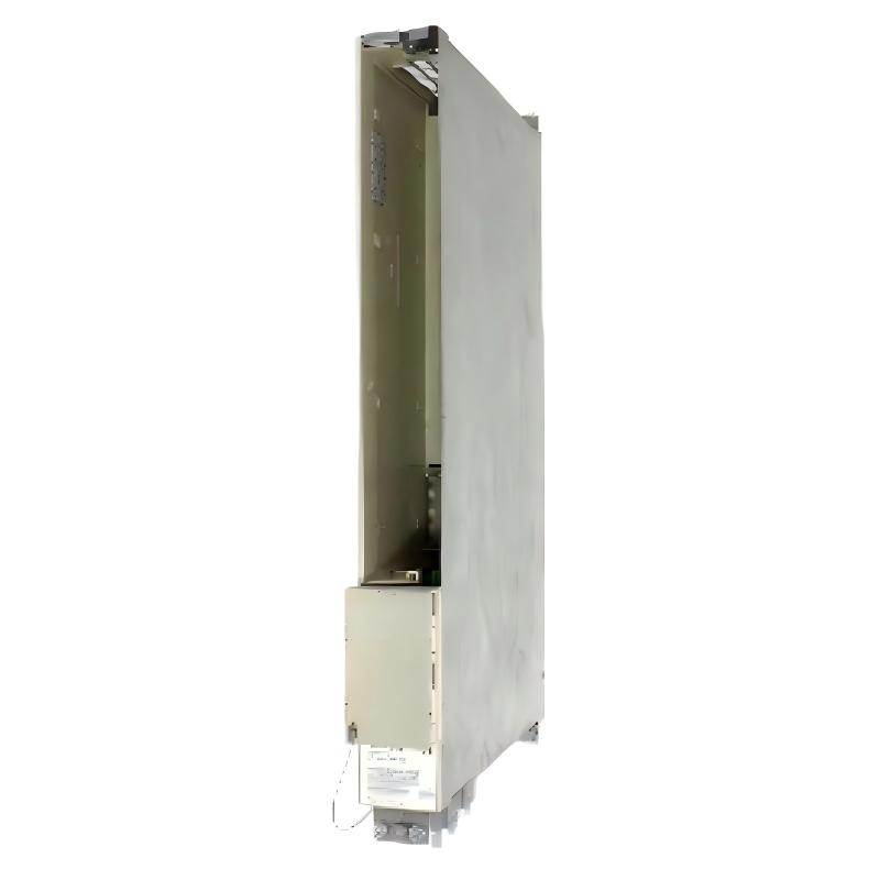
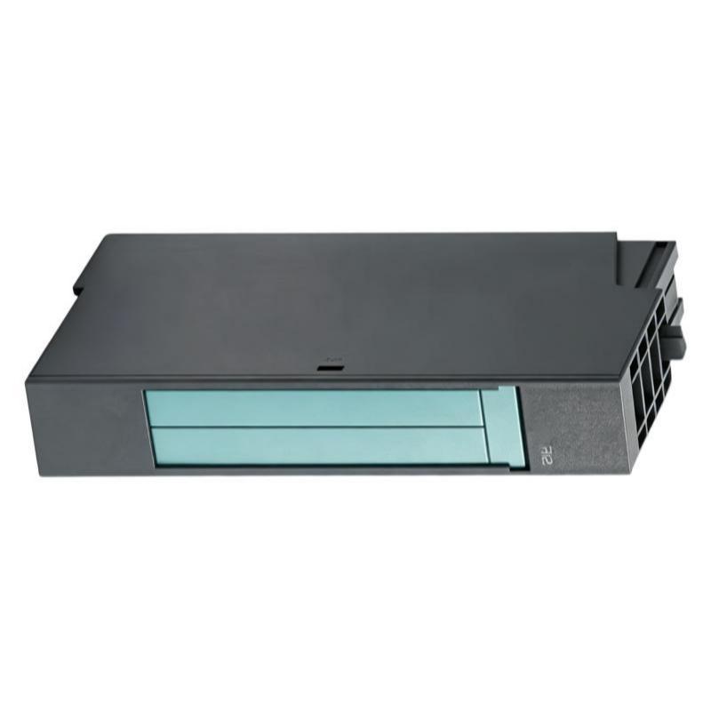
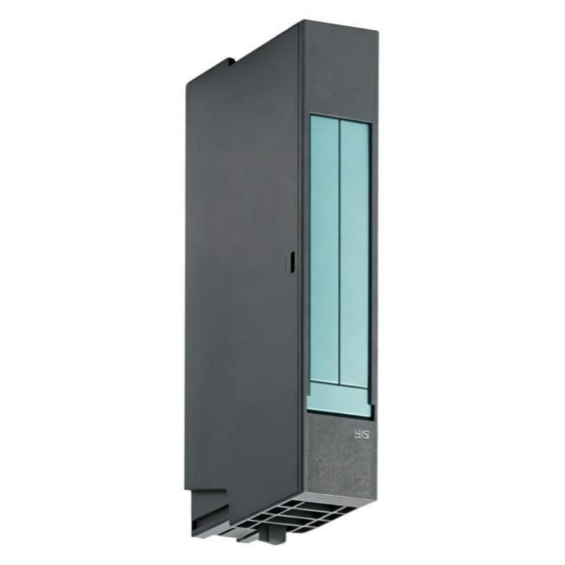
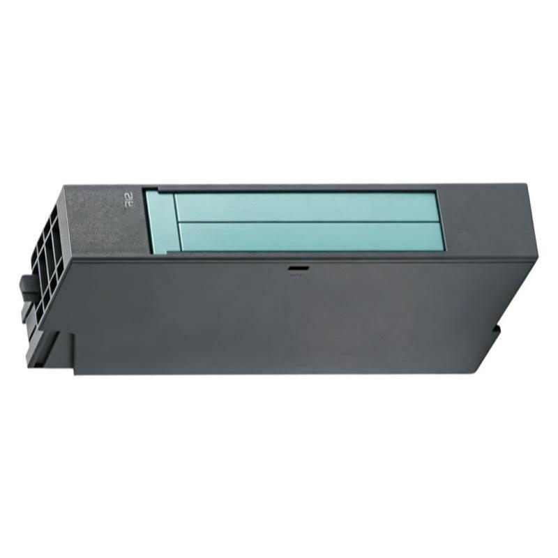
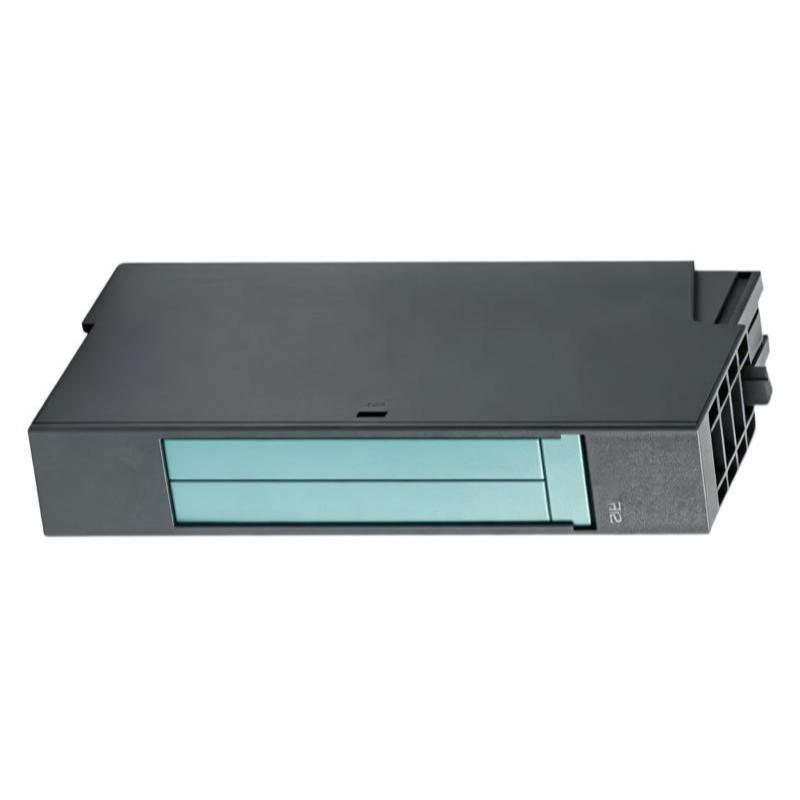
The Siemens 6AG1134-4FB01-2AB0 Analog Input Module is an industrial automation signal-acquisition module designed to interface analog field signals with a Siemens control system. It converts electrical process signals into digital values that can be evaluated by a PLC or automation controller.
Analog input modules are essential when a control system needs to monitor continuously varying process parameters rather than simple ON/OFF states. Typical field signals can represent temperature, pressure, flow, level, position, speed, or other measured process variables.
The 6AG1134-4FB01-2AB0 has a compact form factor of 15 × 81 × 52 mm and a supplied weight of 0.04 kg, making it suitable for compact industrial control cabinets where installation density is important.
The module operates as part of an automation system rather than as an independent measurement instrument. Proper signal wiring, sensor compatibility, grounding, shielding, configuration, and scaling are essential for accurate analog measurement.
Product Information
- Manufacturer: Siemens
- Model: 6AG1134-4FB01-2AB0
- Product Type: Analog Input Module
- Application: Industrial Automation
- Dimensions: 15 × 81 × 52 mm
- Weight: 0.04 kg
- Primary Function: Analog Signal Acquisition
- System Role: Field Signal Interface
Technical Specifications
| Parameter | Specification |
|---|---|
| Manufacturer | Siemens |
| Model | 6AG1134-4FB01-2AB0 |
| Product Type | Analog Input Module |
| Application | PLC / Industrial Automation |
| Primary Function | Analog Signal Acquisition |
| Dimensions | 15 × 81 × 52 mm |
| Weight | 0.04 kg |
| Installation | Control System / Modular I/O Station |
| Signal Type | Analog Field Signals |
| System Function | Measurement and Process Monitoring |
| Typical Signals | Sensor and Transducer Signals |
| Wiring | Field Signal Wiring |
| Maintenance | Periodic inspection recommended |
The exact number of channels, signal ranges, resolution, electrical isolation, diagnostic functions, and supported sensor types should be verified against the configuration of the specific automation system before commissioning.
Function and Working Principle
The main purpose of the 6AG1134-4FB01-2AB0 is to acquire analog signals from field devices and make those measurements available to the automation controller.
A simplified signal path is:
Field Sensor
↓
Analog Signal
↓
6AG1134-4FB01-2AB0
↓
A/D Conversion
↓
Digital Process Value
↓
PLC / Controller
↓
Control Program
For example, a pressure transmitter may generate an analog electrical signal corresponding to the measured pressure.
The analog input module receives the signal, processes it through its input circuitry, converts it into a digital representation, and transfers the resulting process value to the PLC.
The controller can then:
- Display the measurement
- Compare it with alarm limits
- Calculate process values
- Control valves
- Adjust motor speed
- Trigger alarms
- Record process information
- Execute closed-loop control
Role in Industrial Control Systems
Analog input modules provide the connection between physical processes and digital control logic.
A typical system may contain:
Temperature Sensor
↓
Analog Input
↓
PLC
↓
Control Logic
↓
Heating Controller
The same architecture can be used for:
- Pressure monitoring
- Flow measurement
- Tank level monitoring
- Temperature control
- Position feedback
- Speed feedback
- Current measurement
- Voltage measurement
Without a correctly configured analog input module, the PLC cannot reliably interpret continuously varying field signals.
Analog Signal Acquisition
An analog input system normally performs several functions:
1. Signal Reception
The module receives the electrical signal from the field transmitter or sensor.
2. Signal Conditioning
The input circuitry prepares the signal for accurate measurement.
3. Analog-to-Digital Conversion
The electrical signal is converted into a numerical representation.
4. Data Transfer
The resulting digital value is made available to the automation controller.
5. Scaling
The PLC program converts the raw numerical value into an engineering value.
For example:
Raw Input Value
↓
Scaling Function
↓
0–100 bar
The operator can therefore see a meaningful engineering value instead of an internal numerical representation.
Typical Industrial Applications
Process Measurement
The module can be used as part of systems monitoring:
- Pressure
- Temperature
- Flow
- Level
- Humidity
- Position
- Speed
Machine Automation
Analog feedback is frequently required for:
- Servo systems
- Hydraulic systems
- Pneumatic systems
- Motor monitoring
- Machine positioning
- Force measurement
Water and Wastewater
Analog measurements can be used for:
- Tank level
- Flow rate
- Pressure
- Pump monitoring
- Chemical dosing
- Process instrumentation
Manufacturing Lines
The module can acquire signals from:
- Pressure transmitters
- Temperature transmitters
- Position sensors
- Load measurement devices
- Process transducers
- Monitoring instruments
Installation Guide
1. Verify the Product
Before installation, confirm the module identification:
Siemens 6AG1134-4FB01-2AB0
Inspect the module for:
- Cracks
- Damaged terminals
- Bent connectors
- Contamination
- Broken housing
- Signs of overheating
Do not install a damaged module.
2. Switch Off System Power
Before inserting or wiring the module, follow the machine’s approved electrical safety procedure.
Remove power from the relevant system section before performing electrical work.
This reduces the risk of:
- Electrical shock
- Short circuits
- Module damage
- Unexpected machine movement
3. Verify Module Compatibility
Confirm that the controller and I/O station support the module.
Check:
- Hardware configuration
- Module type
- Firmware compatibility
- Bus configuration
- Signal type
- Input range
- Sensor type
- Wiring arrangement
Incorrect configuration can produce inaccurate measurements even when the hardware itself is functioning correctly.
4. Install the Module
Install the module in its designated position within the compatible Siemens automation system.
Ensure that:
- The module is correctly aligned.
- The connector is fully seated.
- Mechanical locking is secure.
- Adjacent modules are correctly positioned.
- No excessive force is applied.
5. Connect the Analog Sensors
Connect the field devices according to the approved electrical drawings.
Before connecting, identify:
- Signal positive
- Signal negative
- Sensor supply
- Shield
- Reference/common connection
Incorrect wiring can result in:
- Zero readings
- Maximum readings
- Unstable readings
- Diagnostic faults
- Sensor damage
6. Check Shielding
Analog signals are more sensitive to electrical interference than many digital signals.
Where shielded instrumentation cable is required, ensure that the shielding arrangement follows the plant grounding design.
Keep analog signal wiring away from:
- Variable-frequency drive cables
- Motor power cables
- Contactor wiring
- High-current conductors
- Switching power supplies
This reduces electromagnetic interference.
7. Configure the Input
The PLC hardware configuration should match the actual field device.
Verify:
- Input channel
- Signal type
- Measurement range
- Diagnostic settings
- Engineering units
- Scaling
- Filtering
For example, a transmitter configured for one signal range should not be interpreted by the PLC using a different range.
8. Perform Commissioning
After wiring and configuration:
- Power the system.
- Check module diagnostics.
- Confirm that the input channel is recognized.
- Apply a known field signal.
- Compare the PLC value with the expected value.
- Verify scaling.
- Check signal stability.
- Confirm alarm limits.
- Record the commissioning result.
Commissioning Example
Suppose an analog transmitter represents a process measurement over a defined input range.
The commissioning procedure should verify:
Minimum Input
↓
PLC Minimum Process Value
and
Maximum Input
↓
PLC Maximum Process Value
A midpoint test should also be performed where practical.
For example:
| Test Point | Expected Result |
|---|---|
| Minimum signal | Minimum engineering value |
| Approximately 25% | Approximately 25% process value |
| Approximately 50% | Approximately 50% process value |
| Approximately 75% | Approximately 75% process value |
| Maximum signal | Maximum engineering value |
This helps identify incorrect scaling and wiring errors.
Troubleshooting Guide
Problem 1: Analog Input Shows Zero
Possible causes:
- Broken signal wire
- Incorrect terminal connection
- Sensor not powered
- Incorrect input configuration
- Open circuit
- Incorrect signal type
- Module fault
Recommended Checks
- Check the field transmitter.
- Check sensor power.
- Check wiring continuity.
- Verify terminal assignment.
- Verify the configured input range.
- Check module diagnostics.
Problem 2: Analog Input Shows Maximum Value
Possible causes include:
- Incorrect signal polarity
- Open-circuit detection
- Incorrect scaling
- Wrong sensor range
- Short circuit or wiring problem
- Configuration mismatch
Check the actual field signal with an appropriate measuring instrument before replacing the module.
Problem 3: Analog Value Fluctuates
Possible causes:
- Electrical interference
- Poor shielding
- Grounding problem
- Loose terminal
- Unstable transmitter
- Long signal cable
- Cable routed near high-power wiring
- Incorrect filtering
Recommended Solution
Inspect the complete signal path from the sensor to the PLC.
Pay particular attention to:
- Shielding
- Grounding
- Cable routing
- Terminal tightness
- Sensor power quality
Problem 4: Analog Value Is Incorrect but Stable
This is often a scaling or configuration problem.
Possible causes:
- Wrong input range
- Incorrect engineering-unit scaling
- Wrong sensor configuration
- Incorrect PLC conversion formula
- Offset error
- Sensor calibration problem
Compare the actual electrical input with the PLC’s calculated engineering value.
Problem 5: Input Value Has a Constant Offset
Possible causes:
- Sensor calibration error
- Incorrect scaling
- Incorrect zero point
- Wiring resistance
- Signal conditioning issue
- Incorrect transmitter configuration
Determine whether the offset originates in the field instrument or the PLC input channel.
Problem 6: Module Reports a Diagnostic Fault
Possible causes:
- Hardware configuration mismatch
- Wiring problem
- Signal outside the permitted range
- Module communication problem
- Power-supply issue
- Hardware fault
Start with the diagnostic information before replacing hardware.
Problem 7: Multiple Analog Channels Fail
If several channels fail simultaneously, do not immediately assume that all sensors have failed.
Possible common causes include:
- Module power problem
- Backplane problem
- Common wiring fault
- Shared sensor supply failure
- Grounding problem
- Configuration problem
- Communication fault
A common failure affecting several channels usually indicates a shared system issue.
Problem 8: Only One Channel Is Incorrect
If all other channels operate normally, investigate:
- Individual sensor
- Individual wiring
- Terminal connection
- Channel configuration
- Channel-specific fault
Comparing the problematic channel with a known-good channel can significantly speed up troubleshooting.
Analog Signal Fault Diagnosis
A systematic diagnostic path is recommended:
Field Sensor
↓
Sensor Power
↓
Signal Cable
↓
Terminal Connection
↓
6AG1134-4FB01-2AB0
↓
I/O Communication
↓
PLC Raw Value
↓
Scaling
↓
Engineering Value
↓
HMI / Control Logic
This method prevents technicians from replacing the analog module before checking simpler causes such as wiring, configuration, or sensor problems.
Preventive Maintenance
| Inspection Item | Recommended Check |
|---|---|
| Module Housing | Check for damage |
| Terminals | Check tightness |
| Field Wiring | Inspect insulation |
| Shielding | Check grounding arrangement |
| Sensor | Verify operating condition |
| Input Values | Compare with reference |
| Configuration | Verify periodically |
| Diagnostics | Review system alarms |
| Cable Routing | Check for interference |
| Scaling | Verify engineering values |
Common Installation Mistakes
Incorrect Signal Range
One of the most common causes of incorrect analog readings is configuring the input differently from the actual transmitter.
Always make sure:
Field Signal Range = Module Configuration = PLC Scaling
Poor Shielding
Long analog cables can pick up electrical noise.
Avoid routing instrumentation wiring together with high-current motor cables whenever possible.
Incorrect Grounding
Improper grounding can create:
- Signal offsets
- Noise
- Ground loops
- Unstable readings
The grounding arrangement should be designed consistently across the entire instrumentation system.
Loose Terminals
A slightly loose analog terminal can cause intermittent readings that are difficult to diagnose.
Inspect terminals during commissioning and preventive maintenance.
Incorrect Scaling
A correctly measured electrical signal can still display an incorrect engineering value if the PLC scaling formula is wrong.
Always test at multiple points.
Advanced Troubleshooting Strategy
When diagnosing an analog measurement problem, divide the system into four sections.
Section 1 — Field Instrument
Check:
- Sensor supply
- Sensor output
- Calibration
- Instrument status
Section 2 — Wiring
Check:
- Continuity
- Polarity
- Shielding
- Grounding
- Terminal connections
Section 3 — Analog Input Module
Check:
- Module recognition
- Diagnostics
- Channel configuration
- Input value
Section 4 — PLC Program
Check:
- Raw value
- Scaling
- Offset
- Engineering units
- Alarm thresholds
This structured approach is generally more efficient than replacing modules one by one.
Key Advantages
- Compact 15 × 81 × 52 mm design
- Lightweight 0.04 kg construction
- Designed for Siemens industrial automation systems
- Provides analog field signal acquisition
- Suitable for process monitoring
- Supports integration of continuous-variable sensors
- Enables PLC-based measurement and control
- Suitable for compact control cabinets
- Supports systematic process instrumentation
- Can be integrated into machine and process automation architectures
Technical FAQs
What is the Siemens 6AG1134-4FB01-2AB0?
The 6AG1134-4FB01-2AB0 is a Siemens analog input module used to acquire analog signals from field devices and transfer measurement data to an industrial control system.
What is its primary function?
Its primary function is to receive analog field signals, convert them into digital process values, and make those values available to the PLC or automation controller.
What types of equipment can provide signals to an analog input module?
Depending on the module’s supported electrical characteristics, typical sources include:
- Temperature transmitters
- Pressure transmitters
- Flow transmitters
- Level transmitters
- Position sensors
- Current-output instruments
- Voltage-output instruments
The actual compatible signal types must be verified for the specific hardware configuration.
What are the dimensions?
The supplied dimensions are 15 × 81 × 52 mm.
What is the weight?
The supplied weight is 0.04 kg.
Why does an analog input show zero?
Possible causes include broken wiring, incorrect terminal connections, missing sensor power, incorrect configuration, an open circuit, or a field-device fault.
Why does the analog value fluctuate?
Electrical interference, poor shielding, grounding problems, loose terminals, unstable sensors, or incorrect cable routing can cause fluctuating readings.
Why is the analog value stable but incorrect?
A stable incorrect value often indicates incorrect scaling, configuration, sensor calibration, or an offset problem.
Why do several analog channels fail at the same time?
A common power, communication, configuration, grounding, or module-level problem may affect multiple channels simultaneously.
Why does only one analog channel fail?
If other channels operate normally, investigate the individual sensor, field wiring, terminal, channel configuration, and channel-specific hardware.
How can I troubleshoot an analog signal efficiently?
Follow the signal path from the field sensor → wiring → terminal → analog input module → PLC raw value → scaling → engineering value.
Is shielding important for analog signals?
Yes. Analog signals can be sensitive to electromagnetic interference, particularly when long cables are used or cables run close to motors and variable-frequency drives.
Can I replace the module without checking the sensor?
Replacing the module should generally not be the first troubleshooting step. Verify the field signal, wiring, configuration, and diagnostics first.
Conclusion
The Siemens 6AG1134-4FB01-2AB0 Analog Input Module provides the interface between analog field instrumentation and a Siemens industrial automation system. With a compact 15 × 81 × 52 mm footprint and a supplied weight of 0.04 kg, it is suitable for applications where control cabinet space and efficient I/O integration are important.
The module can form an important part of a measurement chain involving sensors, transmitters, PLC hardware, engineering-unit scaling, HMI visualization, and control logic. Reliable measurement depends not only on the module itself but also on correct sensor selection, wiring, shielding, grounding, configuration, and PLC programming.
During installation, technicians should verify the complete signal path before commissioning. During troubleshooting, the most effective approach is to isolate the problem between the field instrument, wiring, input module, and PLC software rather than immediately replacing hardware.
For long-term reliability, periodic inspection of terminals, field wiring, shielding, module diagnostics, sensor performance, and scaling is recommended. Proper commissioning and preventive maintenance can significantly reduce intermittent analog-signal faults and improve the stability of industrial measurement and control systems.