

ProductPRODUCT
Featured products



Contact Us
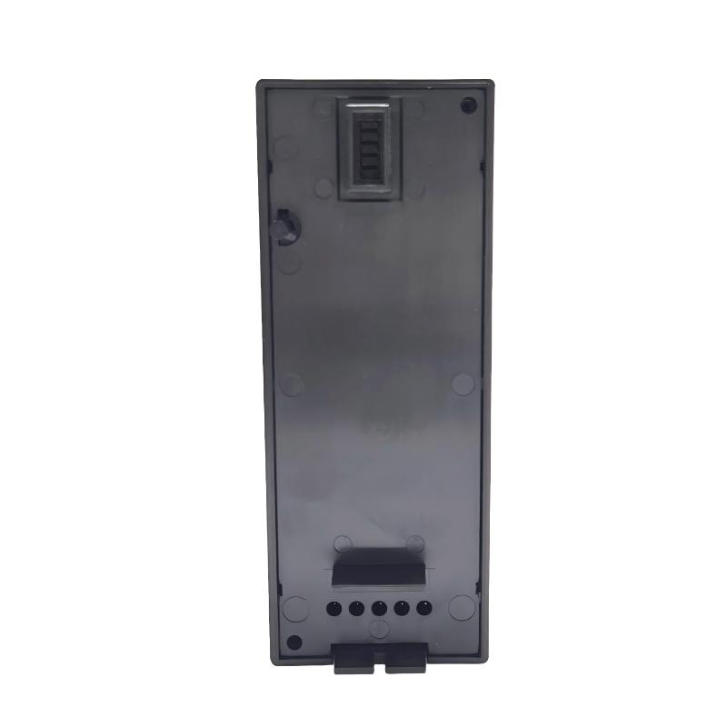
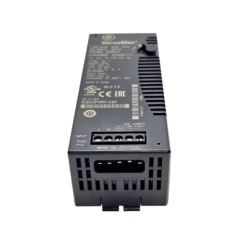
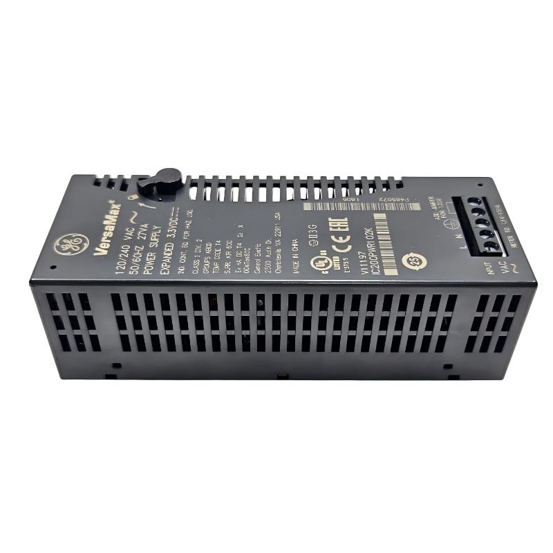
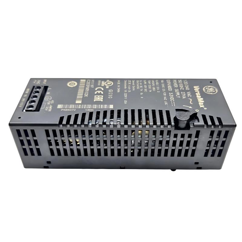
- GE
- IC200PER102
- Power Supply
- USA
- 127 × 64 × 51 mm
- 0.42 kg
- Xiamen, China
- New & In Stock
- T/T, PayPal, Western Union
- 1 Year
- 1-3 Working Days
- DHL, UPS, TNT, FedEx and EMS.
- 24-Hour Service
- COO
- 53
Our advantage

Global Logistics
We have a 10-year logistics and express cooperation agreement, so our products can be shipped to any place in the world.

Brand new and original
Our products are imported in bulk from the place of origin. Because of the cooperative relationship, our products are all original and 100% new.

24-hour service
We provide 7*24 hours service to our customers. We will be there whenever you need us.

Price advantage
All our products are priced very favorably because we have our own warehouse and supply.
| Company Information | |||
| [email protected] | |||
| Mobile | +8615980777398 | ||
| +8615980777398 | |||
| 15980777398 |
Product Overview
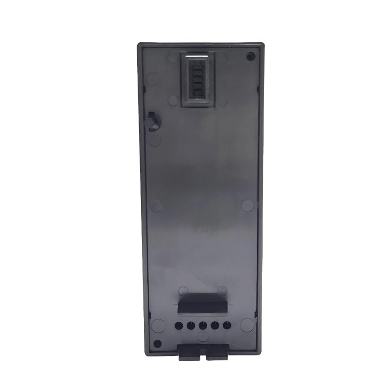
The GE IC200PER102 VersaMax Power Supply is a power-related component used within the GE VersaMax industrial automation platform. Its primary role is to provide the required electrical power interface for the associated VersaMax control and I/O architecture.
In a modular PLC or distributed I/O system, stable power is fundamental to reliable operation. Controllers, communication interfaces, I/O modules, and associated field circuits all depend on properly designed and maintained power distribution. A power-supply problem can therefore appear as an I/O communication failure, module fault, controller reset, or intermittent machine malfunction.
The IC200PER102 is designed as part of the VersaMax modular architecture, allowing the system to maintain an organized power arrangement within an industrial control cabinet.
The supplied product information is:
- Manufacturer: GE
- Product Family: VersaMax
- Model: IC200PER102
- Product Type: Power Supply
- Dimensions: 127 × 64 × 51 mm
- Weight: 0.42 kg
- Application: Industrial Automation
- Primary Function: Power Distribution / System Power Support
The exact input voltage, output voltage, current capacity, protection characteristics, power terminals, grounding requirements, and supported VersaMax configurations should be verified against the applicable equipment documentation before installation.
Technical Specifications
| Parameter | Specification |
|---|---|
| Manufacturer | GE |
| Product Family | VersaMax |
| Model | IC200PER102 |
| Product Type | Power Supply |
| Main Function | VersaMax System Power Support |
| Application | Industrial Automation |
| Dimensions | 127 × 64 × 51 mm |
| Weight | 0.42 kg |
| Installation | Industrial Control Cabinet / VersaMax System |
| System Architecture | Modular PLC / Distributed I/O |
| Electrical Role | System Power Interface |
| Typical Application | VersaMax Automation System |
Function and Working Principle
The IC200PER102 participates in the power architecture of the VersaMax automation system.
A simplified system arrangement is:
Incoming Electrical Supply
↓
Power Supply
↓
VersaMax Control / I/O Architecture
↓
Controller + Communication + I/O Modules
↓
Field Devices
The power supply converts or conditions the applicable incoming electrical power into the required power used by the associated automation system.
Stable power is essential because abnormal voltage conditions can affect:
- PLC operation
- I/O modules
- Communication interfaces
- Processor operation
- Network communication
- Output devices
- System diagnostics
A power supply problem may therefore produce symptoms that initially appear unrelated to the power system.
For example, a sudden voltage drop may cause a controller restart. The resulting restart may then appear as a communication failure or I/O fault.
For this reason, power should always be checked early during troubleshooting.
Role in Industrial Control Systems
A typical automation system can be represented as:
Incoming Power
↓
Power Supply
↓
PLC / Controller
↓
I/O System
↓
Field Devices
The power supply is therefore a foundational component of the control architecture.
It supports reliable operation of the control system by providing an appropriate electrical source for the equipment connected to it.
Typical system-level functions include:
- Powering automation components
- Supporting remote I/O
- Supporting control-system electronics
- Maintaining stable system operation
- Providing organized cabinet power distribution
- Supporting communication and I/O equipment
Typical Industrial Applications
Machine Automation
The IC200PER102 can be incorporated into industrial control cabinets serving:
- Assembly machinery
- Packaging equipment
- Production machines
- Material-handling systems
- Automated work cells
- Conveyor systems
Reliable power is especially important where a loss of control power can stop the complete production sequence.
Distributed I/O Systems
VersaMax systems may use distributed I/O stations located near field equipment.
A typical arrangement can include:
Main Controller
↓
Industrial Network
↓
Remote VersaMax Station
↓
I/O Modules
↓
Sensors and Actuators
A suitable power architecture is required at the local station to maintain reliable operation.
Process Automation
Industrial processes often contain numerous controllers and I/O modules operating continuously.
Potential applications include:
- Pump stations
- Valve systems
- Utility equipment
- Process skids
- Material handling
- Water-treatment equipment
- Manufacturing processes
Stable control power is essential for maintaining process availability.
Installation Guide
1. Verify Product Identification
Before installation, verify:
GE IC200PER102
Inspect the unit for:
- Cracked housing
- Physical deformation
- Damaged terminals
- Broken mounting features
- Signs of overheating
- Corrosion
- Contamination
- Damaged connectors
Do not install a visibly damaged power supply.
2. Review the Electrical Design
Before connecting the power supply, verify the approved electrical drawings.
Confirm:
- Incoming supply
- Required voltage
- Polarity where applicable
- Grounding
- Protective devices
- Output connections
- Load requirements
- Cabinet distribution
Never determine the supply voltage solely from the physical appearance of the module.
3. Verify Power Requirements
Before energizing the unit, confirm that the incoming electrical supply is compatible with the specific IC200PER102 installation.
Important parameters include:
- Nominal input voltage
- Allowable voltage range
- Frequency where applicable
- Input current
- Output requirements
- Load capacity
- Protective-device rating
Using an incorrect supply can cause immediate equipment damage.
4. Install the Power Supply
Install the IC200PER102 in the designated control-system location.
Verify:
- Correct orientation
- Secure mounting
- Adequate clearance
- Proper ventilation
- Accessible wiring
- Proper mechanical support
Do not obstruct ventilation openings.
5. Connect Protective Grounding
Follow the approved grounding design.
Verify:
- Ground conductor
- Cabinet bonding
- Grounding point
- Terminal integrity
- Ground continuity
A reliable grounding arrangement helps reduce electrical noise and improves overall equipment safety.
6. Connect the Input Supply
Connect the incoming supply according to the approved wiring diagram.
Before applying power, inspect:
- Supply conductors
- Terminal tightness
- Polarity
- Protective device
- Cable insulation
- Ground connection
Incorrect wiring can damage the power supply and connected equipment.
7. Connect the System Load
Connect the applicable VersaMax control or I/O system according to the approved system design.
Verify that the total connected load remains within the applicable power capacity.
Consider:
- Controller consumption
- Communication module consumption
- I/O module consumption
- Expansion equipment
- Startup/inrush requirements
Commissioning Procedure
Step 1 — Mechanical Inspection
Confirm that the IC200PER102 is securely mounted.
Step 2 — Wiring Inspection
Verify all input, output, and ground connections.
Step 3 — Supply Verification
Measure the incoming supply before connecting it to the equipment.
Step 4 — Load Verification
Confirm that the connected VersaMax system is compatible with the power arrangement.
Step 5 — Initial Energization
Apply power according to the approved commissioning procedure.
Step 6 — Observe System Status
Check the power supply and connected automation equipment for abnormal conditions.
Step 7 — Verify Controller Operation
Confirm that the PLC or controller starts normally.
Step 8 — Verify I/O Modules
Check that expected I/O modules operate correctly.
Step 9 — Verify Communication
Confirm that communication interfaces and remote I/O stations are functioning normally.
Step 10 — Load Test
Operate the connected automation equipment under normal conditions.
Step 11 — Monitor Stability
Observe the system during startup, normal operation, and load changes.
Troubleshooting Guide
Problem 1: VersaMax System Does Not Power Up
Possible causes include:
- No incoming power
- Incorrect supply voltage
- Open protective device
- Wiring problem
- Power-supply fault
- Short circuit
- Excessive load
- Grounding problem
Recommended Checks
- Verify incoming power.
- Check protective devices.
- Inspect wiring.
- Verify input voltage.
- Check grounding.
- Inspect connected loads.
- Investigate the power supply.
Problem 2: Power Is Present but the Controller Does Not Start
Possible causes include:
- Insufficient output power
- Incorrect supply voltage
- Overload
- Wiring problem
- Controller problem
- Backplane problem
- Power instability
Check the power source under actual load conditions rather than only measuring an unloaded voltage.
Problem 3: PLC Resets Intermittently
Intermittent resets can be associated with:
- Voltage dips
- Power-supply instability
- Excessive loading
- Loose terminals
- Electrical interference
- Short-duration power interruptions
- Overheating
Monitor the power system during the exact period when the controller resets.
Problem 4: I/O Modules Frequently Go Offline
Possible causes include:
- Unstable system power
- Backplane problem
- Communication issue
- Power overload
- Loose connections
- Faulty I/O module
If multiple I/O modules become unavailable simultaneously, investigate the shared power architecture before replacing individual modules.
Problem 5: Communication Modules Repeatedly Lose Communication
Communication problems can be caused by unstable power.
Check:
- Power-supply voltage
- Grounding
- Communication wiring
- Network equipment
- Controller status
- Remote I/O station power
If communication problems occur simultaneously with controller resets or I/O interruptions, power quality should be investigated carefully.
Problem 6: Power Supply Overheats
Possible causes include:
- Excessive load
- Insufficient ventilation
- High cabinet temperature
- Blocked airflow
- Incorrect installation
- Internal component degradation
- Electrical overload
Check the total system load and cabinet temperature.
Problem 7: Output Voltage Drops Under Load
Possible causes include:
- Excessive load
- Wiring resistance
- Loose terminals
- Overload protection
- Power-supply degradation
- Inadequate conductor sizing
Measure voltage at the power supply and at the load to determine whether the voltage loss occurs within the supply or along the distribution path.
Problem 8: System Works at Low Load but Fails During Machine Startup
This is a significant diagnostic clue.
Potential causes include:
- Startup current
- Inrush current
- Excessive load
- Voltage sag
- Insufficient power capacity
- Weak field supply
- Shared supply loading
Measure the supply during the actual startup event.
A system that works correctly while idle may still experience a substantial voltage drop when multiple devices start simultaneously.
Problem 9: Replacement Power Supply Does Not Resolve the Problem
If replacing the IC200PER102 does not correct the issue, investigate:
- Incoming supply
- Protective devices
- Wiring
- Grounding
- Connected load
- Cabinet temperature
- Controller
- I/O modules
- Backplane
- External power consumers
Repeated replacement without examining the surrounding electrical system can lead to unnecessary maintenance costs.
Power Quality Considerations
Stable power is essential to PLC reliability.
Important characteristics include:
- Voltage stability
- Short-duration voltage dips
- Electrical noise
- Harmonic distortion
- Grounding
- Switching transients
- Startup current
- Load fluctuations
A control system can experience intermittent faults even when a basic voltage measurement appears normal.
For difficult faults, voltage should be monitored during actual machine operation.
Load Calculation
Before commissioning, estimate the total connected load.
A simplified calculation is:
Total Load = Controller Load + I/O Load + Communication Load + Expansion Load + Auxiliary Load
The selected power architecture should provide sufficient capacity for the normal operating load and expected transient conditions.
Do not operate a power supply continuously at a level beyond its applicable specification.
Preventive Maintenance
| Inspection Item | Recommended Check |
|---|---|
| Housing | Inspect for damage |
| Mounting | Verify secure installation |
| Input Wiring | Check terminals |
| Grounding | Verify continuity |
| Supply Voltage | Measure periodically |
| Output Power | Check stability |
| Cabinet Temperature | Monitor operating conditions |
| Ventilation | Remove obstructions |
| Connected Load | Review periodically |
| Protective Devices | Check condition |
| Terminals | Inspect for heating/loosening |
| Diagnostics | Review recurring faults |
Preventive maintenance is particularly important in control cabinets operating continuously or under high thermal and electrical loads.
Power Supply Wiring Best Practices
Use Correct Protective Devices
The incoming supply should be protected according to the approved electrical design.
Protection should account for:
- Supply voltage
- Expected current
- Wiring capacity
- Short-circuit conditions
- Equipment requirements
Keep Power and Communication Wiring Properly Routed
Where possible, separate power wiring from sensitive communication and signal wiring.
This can reduce the possibility of electrical interference.
Maintain Secure Terminations
Loose power terminals can create:
- Voltage drops
- Heat generation
- Intermittent operation
- Equipment resets
- Electrical arcing
Terminations should be checked during scheduled maintenance.
Maintain Adequate Ventilation
Heat is an important factor in power-supply reliability.
Avoid:
- Blocked ventilation
- Excessive cabinet temperature
- Poor airflow
- Installation directly next to high-heat equipment without adequate spacing
Systematic Fault Diagnosis
A structured troubleshooting path should be followed.
Stage 1 — Incoming Supply
Verify the electrical source.
↓
Stage 2 — Protection
Check breakers, fuses, and other protective devices.
↓
Stage 3 — IC200PER102 Input
Verify that the correct supply reaches the power supply.
↓
Stage 4 — Power Output
Check the applicable output power under load.
↓
Stage 5 — Distribution
Verify wiring and terminal connections.
↓
Stage 6 — Controller
Check PLC startup and stability.
↓
Stage 7 — I/O
Check local and remote I/O operation.
↓
Stage 8 — Communication
Verify network and communication modules.
↓
Stage 9 — Field Devices
Check downstream equipment.
This approach helps distinguish:
Incoming Power Problem
from
Protection Problem
from
Power Supply Problem
from
Distribution Problem
from
Controller Problem
from
I/O Problem
from
Communication Problem
from
Field Device Problem
IC200PER102 Troubleshooting Table
| Symptom | Possible Cause | Recommended Check |
|---|---|---|
| System completely dead | No supply/power fault | Check incoming power |
| Controller does not start | Output/power issue | Check supply under load |
| PLC resets | Voltage dip/overload | Monitor power during reset |
| I/O modules offline | Power/backplane issue | Check shared supply |
| Communication drops | Power/network issue | Check power and network |
| Power supply overheats | Excessive load/poor ventilation | Check load and airflow |
| Output drops under load | Overload/wiring | Measure voltage under load |
| Startup causes failure | Inrush/voltage sag | Monitor startup event |
| Replacement does not help | External fault | Check supply and loads |
Key Advantages
- GE VersaMax system compatibility
- Designed for industrial automation power applications
- Supports modular automation architectures
- Suitable for control-system installations
- Compact physical form
- Dimensions of 127 × 64 × 51 mm
- Supplied weight of 0.42 kg
- Suitable for PLC and distributed I/O environments
- Supports organized cabinet power architecture
- Can be integrated into machine and process-control systems
Technical FAQs
What is GE IC200PER102?
The GE IC200PER102 is a VersaMax Power Supply used within GE industrial automation architectures to provide the required power interface for associated control-system equipment.
What is the main function of IC200PER102?
Its main function is to provide appropriate electrical power for the applicable VersaMax automation system and its associated components.
What are the dimensions of IC200PER102?
The supplied dimensions are:
127 × 64 × 51 mm
What is the weight of IC200PER102?
The supplied product information specifies:
0.42 kg
Is IC200PER102 a PLC controller?
No. It is a power-supply component rather than a PLC processor.
Why is power supply important in a VersaMax system?
Controllers, communication modules, I/O modules, and other automation equipment depend on stable power. A power problem can therefore cause controller resets, communication faults, I/O errors, or complete system shutdown.
Why does the PLC reset intermittently?
Possible causes include voltage dips, overload, loose terminals, unstable power, electrical interference, excessive temperature, or other power-quality problems.
Why do several I/O modules fail simultaneously?
If several modules fail at the same time, investigate shared power, backplane connections, communication infrastructure, and common wiring before replacing individual I/O modules.
Why does the system work normally when idle but fail during startup?
Startup may create a temporary increase in electrical demand. Inrush current or voltage sag can cause the control system to reset or lose I/O communication.
Why does the power supply overheat?
Possible causes include excessive load, inadequate ventilation, high cabinet temperature, blocked airflow, or internal degradation.
How can I determine whether IC200PER102 is faulty?
Verify the incoming supply, wiring, protective devices, grounding, connected load, and operating temperature first. Then evaluate the power supply under actual operating conditions. If the input is correct but the required power output is unstable or abnormal under an appropriate load, the power supply becomes a stronger suspect.
Can poor grounding cause control-system problems?
Yes. Poor grounding can contribute to electrical noise, communication problems, unstable control behavior, and other difficult-to-diagnose faults.
Should the power supply be replaced immediately after a PLC power failure?
No. First check the incoming supply, protective devices, wiring, grounding, connected load, and operating environment.
What should be checked if replacing IC200PER102 does not fix the fault?
Check the incoming electrical source, protective devices, field wiring, connected load, controller, I/O modules, backplane, communication equipment, and cabinet temperature.
Conclusion
The GE IC200PER102 VersaMax Power Supply is an important part of a reliable industrial automation power architecture. Although a power-supply fault may initially appear as a PLC, communication, or I/O problem, stable electrical power is fundamental to the operation of the entire control system.
The supplied product dimensions are 127 × 64 × 51 mm, and the stated weight is 0.42 kg.
For installation, technicians should verify the electrical design, incoming supply, grounding, protective devices, mounting, wiring, connected load, and ventilation before energizing the system. During commissioning, the power supply should be evaluated not only under no-load conditions but also during normal machine operation and startup events.