

ProductPRODUCT
Featured products








Contact Us
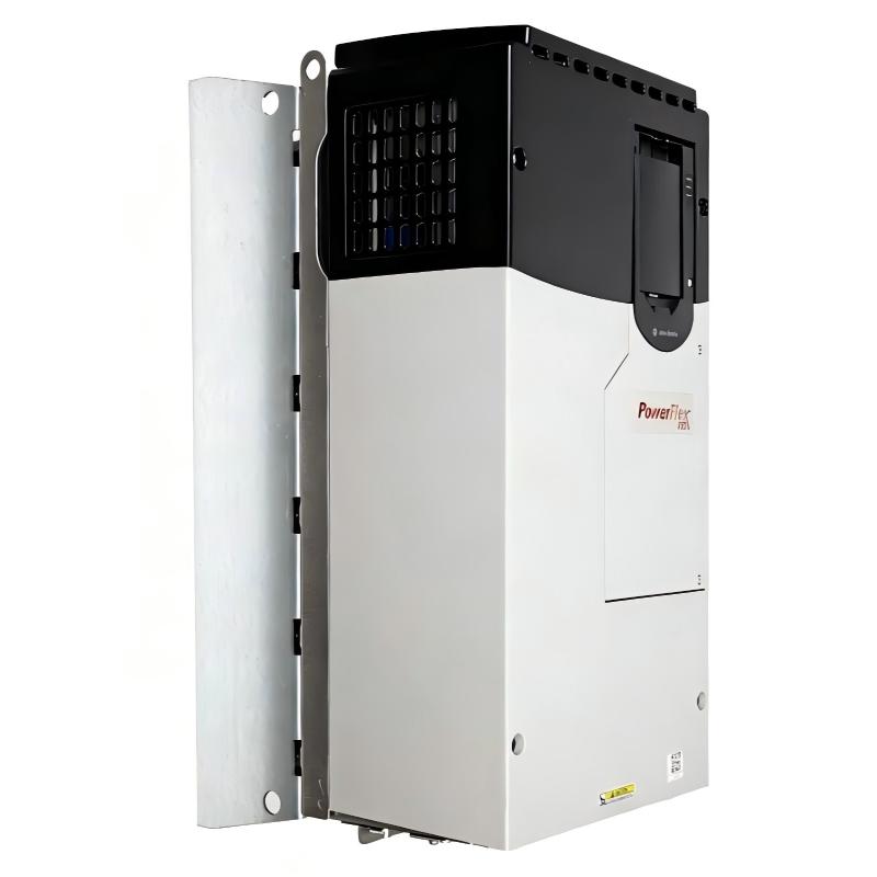
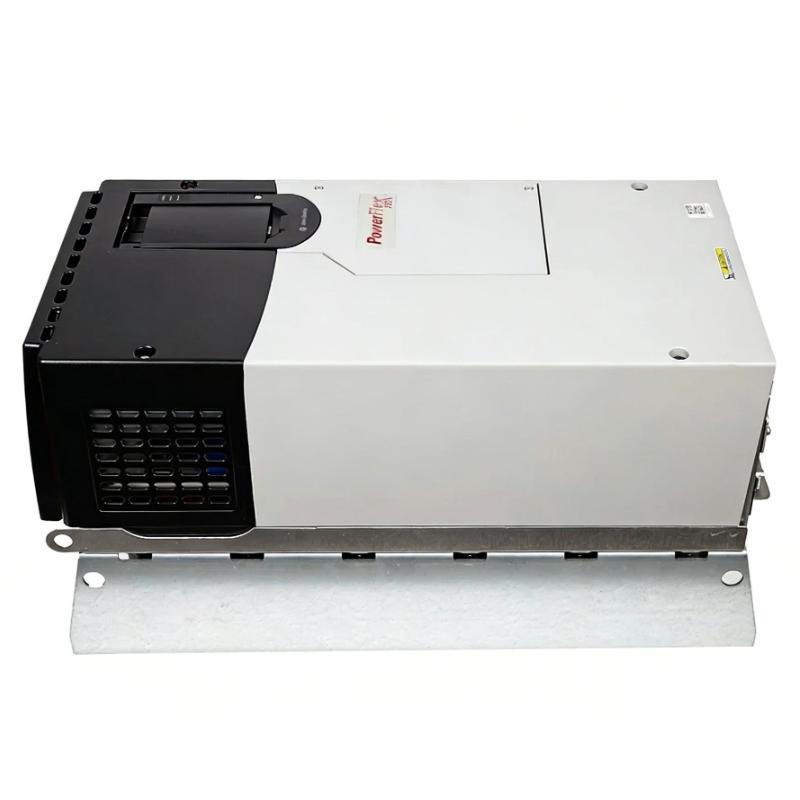
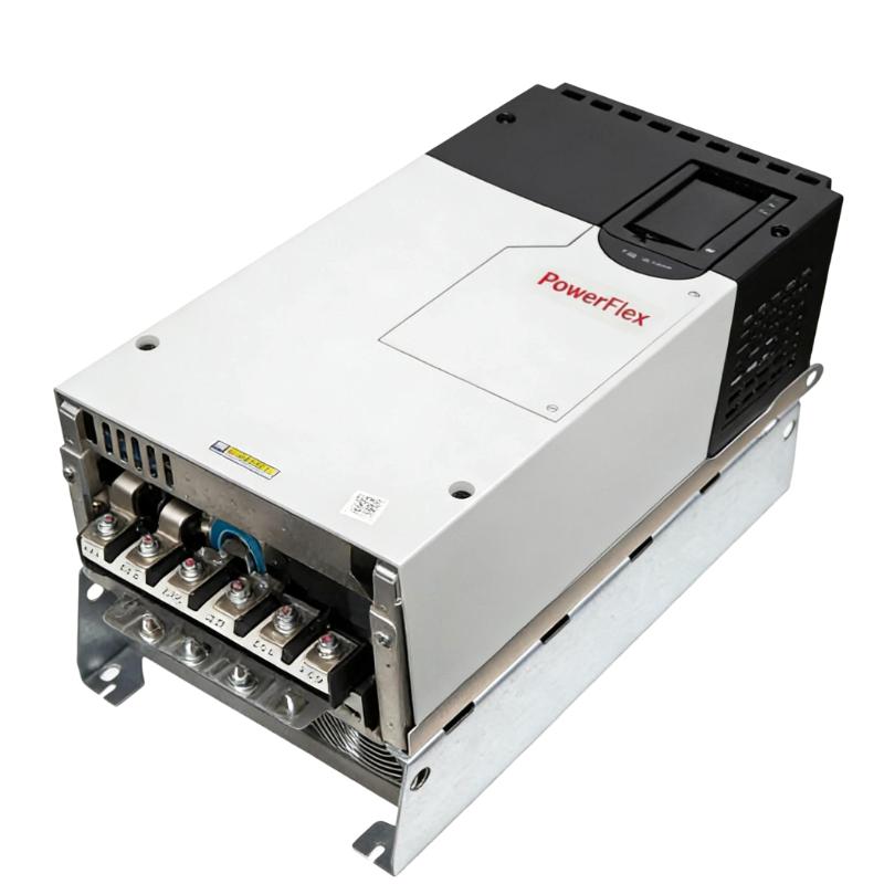
- Allen Bradley
- 20F1ANF171JN0NNNNN
- PowerFlex AC Drive
- USA
- 881.5 × 430 × 349.6 mm
- 108.9kg
- Xiamen, China
- New & In Stock
- T/T, PayPal, Western Union
- 1 Year
- 1-3 Working Days
- DHL, UPS, TNT, FedEx and EMS.
- 24-Hour Service
- COO
- 56
Our advantage

Global Logistics
We have a 10-year logistics and express cooperation agreement, so our products can be shipped to any place in the world.

Brand new and original
Our products are imported in bulk from the place of origin. Because of the cooperative relationship, our products are all original and 100% new.

24-hour service
We provide 7*24 hours service to our customers. We will be there whenever you need us.

Price advantage
All our products are priced very favorably because we have our own warehouse and supply.
| Company Information | |||
| [email protected] | |||
| Mobile | +8615980777398 | ||
| +8615980777398 | |||
| 15980777398 |
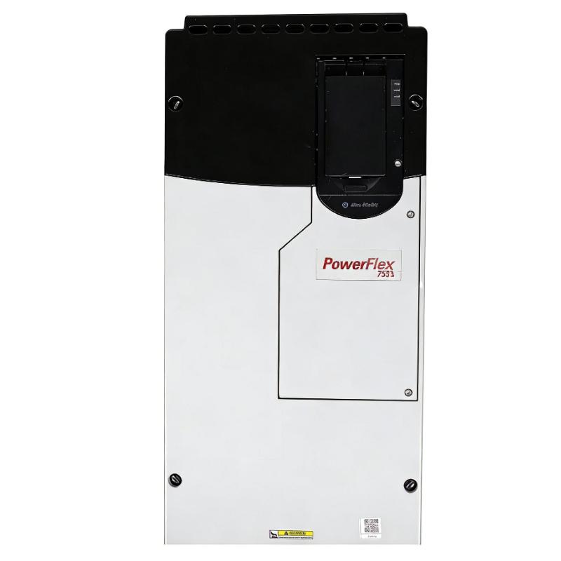
Allen-Bradley 20F1ANF171JN0NNNNN — Detailed Product Specifications, Introduction, Applications, Advantages and Related Models
1. Product Overview
The 20F1ANF171JN0NNNNN is a high-power PowerFlex 753 AC drive designed for large three-phase industrial motors.
It is a 690 VAC, three-phase, 171 A air-cooled variable frequency drive with a 160 kW Normal Duty rating and a 132 kW Heavy Duty rating.
The drive uses a Frame 7 construction and an open-type enclosure. It is intended for applications where a large AC motor needs controlled starting, variable-speed operation, acceleration and deceleration.
One of the most important characteristics of this particular model is that it is the non-dynamic-braking version. The catalog number uses the J configuration for the filtering/common-mode jumper arrangement and the N configuration for the dynamic-braking position, meaning that there is no internal dynamic-braking transistor.
This makes the model especially suitable for applications where dynamic braking is not required, such as many large pumps, fans, blowers and other variable-speed industrial machines.
The drive includes embedded I/O, an AC input with precharge, no DC terminals, forced-air cooling and a filtered configuration with the CM jumper installed.
2. Brand and Product Series
| Item | Specification |
|---|---|
| Brand | Allen-Bradley |
| Product Family | PowerFlex |
| Product Series | PowerFlex 753 |
| Product Type | Air-Cooled AC Variable Frequency Drive |
| Catalog Number | 20F1ANF171JN0NNNNN |
| Drive Architecture | PowerFlex 750-Series Architecture-Class Drive |
| Voltage Class | 690 VAC |
| Input Phase | 3 Phase |
| Output Phase | 3 Phase |
| Normal Duty Current | 171 A |
| Normal Duty Power | 160 kW |
| Heavy Duty Current | 142 A |
| Heavy Duty Power | 132 kW |
| Frame Size | Frame 7 |
| Cooling | Forced Air |
| Enclosure | Open Type |
| Protection | IP00/IP20 class |
| Input Configuration | AC Input with Precharge |
| DC Terminals | None |
| Filtering | Filtered |
| CM Jumper | Installed |
| Dynamic Braking | None |
| Internal Dynamic-Braking Transistor | No |
| Embedded I/O | Yes |
| HIM | Blank / No HIM |
| PID Control | Yes |
| Integrated Motion | No |
3. Detailed Technical Parameters
| Parameter | Specification |
|---|---|
| Model | 20F1ANF171JN0NNNNN |
| Brand | Allen-Bradley |
| Series | PowerFlex 753 |
| Product Type | AC Variable Frequency Drive |
| Input Voltage | 690 VAC |
| Nominal Output Voltage | Up to the applicable motor/output voltage range |
| Input Phase | 3 Phase |
| Output Phase | 3 Phase |
| Nominal Output Current | 171 A |
| Normal Duty Current | 171 A |
| Normal Duty Power | 160 kW |
| Heavy Duty Current | 142 A |
| Heavy Duty Power | 132 kW |
| Motor Power Class | 160 kW ND / 132 kW HD |
| Input Frequency | 50/60 Hz |
| Input Type | AC Input with Precharge |
| DC Terminals | No |
| Cooling Method | Forced Air |
| Frame Size | Frame 7 |
| Enclosure | Open Type |
| IP Classification | IP00/IP20 class |
| Filtering | Filtered |
| CM Jumper | Installed |
| Dynamic Braking | None |
| Internal DB Transistor | No |
| Embedded I/O | Yes |
| PID Control | Yes |
| Integrated Motion | No |
| HIM | No HIM / Blank |
| Installation | Cabinet / Panel |
| Control Characteristic | PID-capable AC motor control |
| Suitable for Safety Functions | Yes, when used within an appropriate safety architecture |
| Operating Temperature | Approximately -20 to +60 °C, subject to applicable conditions and derating |
| Storage Temperature | Approximately -40 to +70 °C |
| Height | 881.5 mm |
| Width | 430 mm |
| Depth | 349.6 mm |
| Dimensions H × W × D | 881.5 × 430 × 349.6 mm |
| Approx. Weight | 72.6–108.9 kg |
| Construction | Frame 7 air-cooled architecture |
| Typical Installation | Industrial electrical cabinet |
| Typical Applications | Pumps, fans, blowers, conveyors, compressors and process machinery |
The Frame 7 dimensional data is approximately 881.5 mm high × 430 mm wide × 349.6 mm deep.
The published approximate weight range for the Frame 7 open-type construction is 72.6–108.9 kg, depending on the specific configuration and installed hardware. For mechanical design, lifting and transportation, the actual configured unit should be checked against the final equipment documentation.
4. Product Introduction
The 20F1ANF171JN0NNNNN is a large industrial variable frequency drive intended for controlling high-power three-phase AC motors.
Its primary purpose is to allow a motor to operate at different speeds rather than simply running at a fixed speed from the electrical supply.
The drive controls the electrical frequency and voltage supplied to the motor, allowing acceleration, deceleration and operating speed to be adjusted according to the requirements of the machine.
For a large industrial motor, this type of control can improve process flexibility and can reduce unnecessary mechanical stress during starting.
It can also allow the motor to operate closer to the actual process demand.
For example, a large pump may not need to operate at full speed all day.
A variable frequency drive can reduce the pump motor speed when the required flow is lower and increase the speed when the process requires more flow.
The same basic principle can be applied to industrial fans, blowers, conveyors, mixers and many other types of machinery.
5. What Makes This Model Different?
The most important difference between 20F1ANF171JN0NNNNN and the closely related 20F1ANF171JA0NNNNN is the dynamic-braking configuration.
| Feature | 20F1ANF171JN0NNNNN | 20F1ANF171JA0NNNNN |
|---|---|---|
| Voltage | 690 VAC | 690 VAC |
| Normal Duty Current | 171 A | 171 A |
| Normal Duty Power | 160 kW | 160 kW |
| Heavy Duty Power | 132 kW | 132 kW |
| Frame | 7 | 7 |
| Filtering | Filtered | Filtered |
| CM Jumper | Installed | Installed |
| Dynamic-Braking Transistor | No | Yes |
| Main Difference | No internal DB transistor | Internal DB transistor |
The JN0 configuration therefore represents the no-internal-braking-transistor version.
This is an important distinction when selecting a replacement or comparing catalog numbers.
6. Understanding the Catalog Number
The model number contains several configuration elements.
| Catalog Number Section | General Meaning |
|---|---|
| 20F | PowerFlex 753 family |
| 1 | Drive architecture |
| A | AC input |
| N | 690 VAC class |
| F | Open-type configuration |
| 171 | 171 A current class |
| J | Filtered configuration / CM jumper installed |
| N | No internal dynamic-braking transistor |
| 0 | No HIM |
| NNNN | No additional option in the corresponding positions |
The J and N positions are particularly important.
The J indicates the filtered configuration with the CM jumper installed.
The N in the dynamic-braking position indicates that the drive does not contain the internal dynamic-braking transistor.
7. Normal Duty and Heavy Duty Ratings
The drive has two principal power ratings.
| Duty Classification | Current | Power | Typical Load |
|---|---|---|---|
| Normal Duty | 171 A | 160 kW | Pumps, fans, blowers and suitable variable-torque loads |
| Heavy Duty | 142 A | 132 kW | Conveyors, mixers and demanding constant-torque loads |
7.1 Normal Duty — 160 kW
The 160 kW Normal Duty rating is the higher power rating of the drive.
This rating is particularly useful for applications where the motor load follows a variable-torque characteristic.
Typical examples include:
- Centrifugal pumps.
- Centrifugal fans.
- Large blowers.
- HVAC equipment.
- Cooling systems.
- Water circulation equipment.
These applications often benefit from reducing motor speed when the process demand is reduced.
7.2 Heavy Duty — 132 kW
The 132 kW Heavy Duty rating is intended for applications with more demanding load conditions.
Examples can include:
- Heavy conveyors.
- Mixers.
- Material-handling systems.
- Process machinery.
- Certain compressors.
- Machinery requiring greater overload capability.
When selecting the drive, the actual motor full-load current should be considered together with the load type.
A motor’s kW rating alone should not be the only selection criterion.
8. Main Product Functions
8.1 Variable-Speed Motor Control
The basic function of the drive is to control the speed of a three-phase AC motor.
The motor can operate at different speeds depending on the process requirements.
This can be useful when a machine does not need maximum motor speed all the time.
8.2 Controlled Acceleration
The drive can gradually increase motor speed according to the programmed acceleration profile.
This can reduce sudden mechanical stress on:
- Couplings.
- Gearboxes.
- Belts.
- Shafts.
- Bearings.
- Conveyor systems.
- Pumping equipment.
8.3 Controlled Deceleration
The drive can control the motor’s reduction in speed.
However, this particular model does not have an internal dynamic-braking transistor.
Therefore, applications involving rapid stopping or large regenerative energy require additional engineering consideration.
For many pump and fan applications, a relatively long controlled ramp-down is acceptable.
For high-inertia machinery, the braking requirements should be evaluated separately.
8.4 PID Process Control
PID control is particularly useful in process applications.
A typical pumping system could use:
Pressure Sensor → PID Control → Drive → Pump Motor
If pressure falls below the desired setpoint, the drive can increase motor speed.
If pressure becomes higher than required, the drive can reduce motor speed.
This provides automatic process regulation without requiring a completely separate speed-control loop.
9. Embedded I/O
The PowerFlex 753 architecture includes embedded I/O.
This can simplify connections to external control devices.
Typical signals can include:
- Start commands.
- Stop commands.
- Speed references.
- Digital inputs.
- Analog process signals.
- Status signals.
- Fault indications.
- Relay outputs.
The actual I/O arrangement should be checked against the machine’s control design.
10. Product Applications
10.1 Large Centrifugal Pumps
Large pumps are one of the strongest application areas for this drive.
Potential applications include:
- Water treatment.
- Industrial water circulation.
- Cooling-water systems.
- Process-water systems.
- Large pumping stations.
- Factory utility systems.
- Industrial fluid-transfer systems.
Variable-speed control can allow the pump to match its output to process demand.
For suitable centrifugal-pump systems, this can also provide significant energy-saving opportunities.
11. Industrial Fans
Large industrial fans can require substantial motor power.
The drive can control fan speed according to:
- Airflow.
- Pressure.
- Temperature.
- Production demand.
- Ventilation requirements.
Instead of continuously running the fan at full speed, the motor can be operated at a lower speed when less airflow is required.
This can improve process control and may reduce energy consumption.
12. Large Blowers
Industrial blowers can also benefit from variable-speed operation.
Typical applications include:
- Factory ventilation.
- Dust collection.
- Furnace systems.
- Process-air systems.
- Waste-treatment equipment.
- Industrial cooling.
- Air-handling systems.
The drive can adjust motor speed according to the required airflow or pressure.
13. Conveyors
The 171 A capacity makes this drive suitable for large conveyor motors.
Applications may include:
- Mining conveyors.
- Bulk-material handling.
- Manufacturing lines.
- Heavy industrial transport systems.
- Production conveyors.
- Transfer systems.
Controlled acceleration can reduce mechanical shock.
However, because this particular drive has no internal dynamic-braking transistor, a conveyor that requires very rapid stopping should be evaluated carefully.
14. Mixers
Large industrial mixers can require substantial torque.
The Heavy Duty rating of 132 kW provides a useful capacity for demanding mixer applications.
Examples include:
- Chemical mixing.
- Industrial blending.
- Material processing.
- Large agitators.
- Manufacturing processes.
The motor’s starting torque and actual load profile should be checked before final selection.
15. Compressors
The drive can be used for suitable compressor applications.
Variable-speed control can be useful where compressor demand changes during production.
However, compressor applications vary significantly.
The following should be evaluated:
- Compressor type.
- Motor current.
- Starting torque.
- Required speed range.
- Continuous load.
- Acceleration requirements.
- Deceleration requirements.
16. Material-Handling Equipment
The drive can be used in large material-handling machinery.
Potential applications include:
- Heavy conveyors.
- Rollers.
- Transfer equipment.
- Industrial transport systems.
- Large positioning equipment.
- Processing lines.
Variable-speed control can make the movement of materials smoother and more controllable.
17. Applications Where This Model Is Less Suitable
The drive is not an ideal choice for every motor.
For example, it is generally excessive for:
- Small pumps.
- Small fans.
- Small conveyors.
- Small machine tools.
- Small packaging machinery.
- Small motors below the drive’s practical capacity.
Using a 171 A, Frame 7 drive for a small motor would normally be unnecessarily expensive and physically large.
A smaller PowerFlex drive would generally be more appropriate.
18. Advantages of 20F1ANF171JN0NNNNN
18.1 High 690 VAC Rating
The 690 VAC class makes the drive suitable for large industrial motor systems.
This voltage class is commonly associated with large motor installations where high-power electrical equipment is required.
18.2 171 A Normal Duty Capacity
The 171 A rating provides considerable motor-control capability.
This allows the drive to handle substantially larger motors than compact general-purpose VFDs.
18.3 160 kW Normal Duty Rating
The 160 kW Normal Duty rating makes this model a strong choice for large variable-torque applications.
It provides substantial capacity for large pumps, fans and blowers.
18.4 132 kW Heavy Duty Rating
The Heavy Duty rating extends the application range into more demanding machinery.
This makes the model more flexible than a drive intended only for variable-torque applications.
18.5 No Unnecessary Braking Hardware
For applications that do not require dynamic braking, the absence of an internal braking transistor can be an advantage.
There is no need to pay for or install braking hardware that the application will never use.
This is particularly relevant to many large pumps and fans.
18.6 Embedded I/O
Embedded I/O makes integration with external control circuits easier.
This can reduce the need for separate basic I/O equipment.
18.7 PID Capability
Built-in PID control is useful for applications involving:
- Pressure.
- Flow.
- Temperature.
- Speed.
- Process setpoints.
This is particularly valuable in pumping and ventilation systems.
18.8 Filtered Configuration
The filtered configuration with the CM jumper installed can be beneficial in applications where electromagnetic compatibility and grounding considerations are important.
The exact grounding arrangement should always be designed according to the electrical system and installation requirements.
19. Dimensions and Weight
The Frame 7 physical size is an important engineering consideration.
| Physical Parameter | Specification |
|---|---|
| Height | 881.5 mm |
| Width | 430 mm |
| Depth | 349.6 mm |
| Overall Dimensions | 881.5 × 430 × 349.6 mm |
| Weight | Approximately 72.6–108.9 kg |
| Frame | Frame 7 |
| Enclosure | Open Type |
| Protection | IP00/IP20 class |
| Cooling | Forced Air |
| Installation | Cabinet / Panel |
The published Frame 7 weight is given as an approximate range of 72.6 to 108.9 kg, depending on the configuration.
This is important when planning:
- Cabinet mounting.
- Lifting equipment.
- Transportation.
- Structural support.
- Installation manpower.
- Maintenance access.
The exact configured weight should be confirmed for the final unit.
20. Cabinet Design
Because this is a Frame 7 drive, the electrical cabinet needs to be designed accordingly.
The cabinet should provide enough room for the drive itself as well as:
- Power cables.
- Control cables.
- Cable bending radius.
- Ventilation.
- Heat dissipation.
- Maintenance access.
- Protective equipment.
- Disconnecting equipment.
- Grounding connections.
Simply having enough physical room to mount the drive is not sufficient.
Thermal performance is also important.
A large AC drive produces heat during normal operation, and the cabinet’s cooling system needs to be designed around the total heat generated by all installed equipment.
21. Cooling
The drive uses forced-air cooling.
Forced-air cooling is particularly important for high-power drives because the electrical components generate considerable heat.
The cabinet should allow sufficient airflow around the drive.
Blocked ventilation paths can increase internal temperature and reduce reliability.
The cooling design should therefore consider:
- Ambient temperature.
- Cabinet temperature.
- Airflow direction.
- Fan operation.
- Dust accumulation.
- Filter condition.
- Installation altitude.
- Total cabinet heat load.
22. Why the No-Braking Configuration Can Be Advantageous
The absence of an internal braking transistor is not automatically a disadvantage.
For many industrial applications, rapid braking is not necessary.
Consider a large centrifugal pump.
When the pump needs to stop, it may be perfectly acceptable to reduce the motor speed gradually over several seconds.
In that situation, the drive does not necessarily need an internal dynamic-braking transistor.
The same principle can apply to many large fans and blowers.
The no-braking configuration can therefore be a sensible choice when the application does not produce substantial regenerative energy.
23. When Dynamic Braking Is Required
Dynamic braking becomes more important when the load needs to stop quickly or contains significant stored mechanical energy.
Typical examples include:
- High-inertia conveyors.
- Hoists.
- Cranes.
- Centrifuges.
- Unwinders.
- Rewinders.
- Large rotating machinery.
- Rapid positioning systems.
In these applications, a braking-enabled version such as 20F1ANF171JA0NNNNN may be a better fit.
The correct braking resistor must still be selected based on actual regenerative energy and duty cycle.
24. Comparison: J Configuration vs. A Configuration
| Feature | 20F1ANF171JN0NNNNN | 20F1ANF171JA0NNNNN |
|---|---|---|
| Voltage | 690 VAC | 690 VAC |
| Current | 171 A | 171 A |
| Normal Duty | 160 kW | 160 kW |
| Heavy Duty | 132 kW | 132 kW |
| Frame | 7 | 7 |
| Filtering | Yes | Yes |
| CM Jumper | Installed | Installed |
| Dynamic-Braking Transistor | No | Yes |
| Best Use | Applications not requiring internal dynamic braking | Applications requiring internal dynamic braking capability |
| Pump/Fan Applications | Excellent | Excellent |
| High-Inertia Applications | Requires additional braking evaluation | Better suited |
| Rapid Deceleration | Less suitable | More suitable |
This is one of the most useful comparisons to make when choosing between these two catalog numbers.
25. Five Recommended Same-Series or Closely Related Models
| Model | Series | Voltage | ND Current | ND Power | HD Current | HD Power | Frame | Braking | Dimensions | Weight |
|---|---|---|---|---|---|---|---|---|---|---|
| 20F1ANF142JN0NNNNN | PowerFlex 753 | 690 VAC | 142 A | 132 kW | 119 A | 110 kW | 6 | None | 665.5 × 308 × 346.4 mm | 38.6 kg |
| 20F1ANF171JN0NNNNN | PowerFlex 753 | 690 VAC | 171 A | 160 kW | 142 A | 132 kW | 7 | None | 881.5 × 430 × 349.6 mm | 72.6–108.9 kg |
| 20F1ANF212JN0NNNNN | PowerFlex 753 | 690 VAC | 212 A | 200 kW | 171 A | 160 kW | 7 | None | 881.5 × 430 × 349.6 mm | 72.6–108.9 kg |
| 20F1ANF263JN0NNNNN | PowerFlex 753 | 690 VAC | 263 A | 250 kW | 212 A | 200 kW | 7 | None | 881.5 × 430 × 349.6 mm | 72.6–108.9 kg |
| 20F1ANF171JA0NNNNN | PowerFlex 753 | 690 VAC | 171 A | 160 kW | 142 A | 132 kW | 7 | Yes | 881.5 × 430 × 349.6 mm | 72.6–108.9 kg |
20F1ANF142JN0NNNNN
This is the most natural lower-capacity alternative.
It remains in the 690 VAC PowerFlex 753 family but drops to 142 A / 132 kW Normal Duty.
It also uses the smaller Frame 6 construction.
For a motor that does not require the full 171 A capacity, this model can provide a more compact solution.
20F1ANF212JN0NNNNN
This is the next major capacity step above the target model.
It provides approximately:
212 A Normal Duty
200 kW Normal Duty
171 A Heavy Duty
160 kW Heavy Duty
It is appropriate when the motor current exceeds the 171 A class.
20F1ANF263JN0NNNNN
This is a higher-capacity Frame 7 configuration.
With approximately 263 A Normal Duty capability and 250 kW Normal Duty power, it is intended for substantially larger motors.
20F1ANF171JA0NNNNN
This is the closest functional alternative to the target model.
The electrical ratings are essentially the same, but the key difference is the internal dynamic-braking transistor.
This makes it the first model to consider when the machine needs braking capability.
26. Five Popular Same-Brand Models
The following models represent useful alternatives within the same brand portfolio, covering both large industrial drives and smaller general-purpose drives.
| Model | Product Series | Voltage | Current / Rating | Power Rating | Frame | Main Feature | Dimensions / Weight |
|---|---|---|---|---|---|---|---|
| 20G1ANF171JA0NNNNN | PowerFlex 755 | 690 VAC, 3 Ph | 171 A class | Approx. 160 kW ND | 7 | Advanced high-power drive | 881.5 × 430 × 349.6 mm class / approx. 72.6–108.9 kg |
| 20G1ANF142JA0NNNNN | PowerFlex 755 | 690 VAC, 3 Ph | 142 A class | Approx. 132 kW ND | 6 | Advanced industrial control | 665.5 × 308 × 346.4 mm class / approx. 38.6 kg |
| 25B-D2P3N114 | PowerFlex 525 | 380–480 VAC, 3 Ph | 2.3 A | Approx. 0.75 kW | Compact | Compact general-purpose drive | Compact / lightweight |
| 25B-D6P0N114 | PowerFlex 525 | 380–480 VAC, 3 Ph | 6.0 A | Approx. 2.2 kW | Compact | Small machinery and motor control | Compact / lightweight |
| 25B-D017N114 | PowerFlex 525 | 380–480 VAC, 3 Ph | 17 A | Approx. 7.5 kW | Compact | General industrial applications | Compact / lightweight |
The PowerFlex 755 models are the closest alternatives when the application remains in the high-power industrial category.
The PowerFlex 525 models are intended for much smaller motors and are not direct electrical replacements for the 20F1ANF171JN0NNNNN.
27. PowerFlex 753 vs. PowerFlex 755
| Feature | PowerFlex 753 | PowerFlex 755 |
|---|---|---|
| Product Position | Industrial architecture-class drive | More advanced architecture-class drive |
| Large Motor Control | Yes | Yes |
| 690 VAC Models | Yes | Yes |
| Embedded I/O | Yes | Yes |
| PID | Yes | Yes |
| Dynamic Braking | Configuration dependent | Configuration dependent |
| Feedback Options | Available | More extensive |
| Advanced Control | Strong | More extensive |
| Motion Capability | Limited | More advanced |
| Typical Applications | Pumps, fans, conveyors, process machinery | Advanced machinery and coordinated applications |
| Complexity | Moderate to high | High |
| Best Selection | General high-power industrial control | Advanced control requirements |
For a large pump, fan, blower or conveyor, the PowerFlex 753 platform can be a practical choice.
When the machine requires more advanced feedback, control or motion functionality, the PowerFlex 755 family is worth considering.
28. Application Suitability
| Application | Suitability | Comments |
|---|---|---|
| Large centrifugal pump | ★★★★★ | Excellent fit |
| Large industrial fan | ★★★★★ | Excellent variable-torque application |
| Large blower | ★★★★★ | Excellent fit |
| Water circulation system | ★★★★★ | PID and speed control are useful |
| HVAC equipment | ★★★★★ | Good variable-speed application |
| Heavy conveyor | ★★★★☆ | Good capacity; braking requirements must be evaluated |
| Mixer | ★★★★☆ | Good if motor/load matches HD rating |
| Compressor | ★★★★☆ | Suitable depending on compressor type |
| Material handling | ★★★★☆ | Good for large motor systems |
| Hoist | ★★★☆☆ | Braking system requires special consideration |
| Crane | ★★★☆☆ | Safety and braking architecture are critical |
| High-inertia centrifuge | ★★★☆☆ | No internal DB transistor |
| Small motor | ★☆☆☆☆ | Excessive capacity |
| Small pump | ★☆☆☆☆ | Smaller drive normally preferred |
29. Energy-Saving Advantages
Variable frequency drives can provide substantial energy-saving opportunities in the right applications.
The biggest opportunities generally occur with variable-torque loads.
Examples include:
- Centrifugal pumps.
- Centrifugal fans.
- Blowers.
When speed is reduced, the power required by a centrifugal load can decrease significantly.
For example, if a cooling fan only needs reduced airflow during part of the day, the motor does not necessarily need to operate at full speed continuously.
The drive can reduce the motor speed to match the actual demand.
This can improve overall system efficiency.
However, energy savings should always be calculated from the actual load profile.
A constant-torque conveyor behaves differently from a centrifugal pump, so the same energy-saving assumptions should not be applied to every application.
30. Installation and Engineering Considerations
Before selecting the 20F1ANF171JN0NNNNN for a machine, several technical points should be checked.
| Engineering Item | What to Check |
|---|---|
| Motor Voltage | Confirm 690 VAC system compatibility |
| Motor Current | Confirm motor current is within applicable drive rating |
| Motor Power | Compare with 160 kW ND / 132 kW HD |
| Duty | Determine Normal Duty or Heavy Duty |
| Load Type | Variable torque or constant torque |
| Starting Torque | Confirm required acceleration torque |
| Deceleration | Determine required stopping time |
| Regenerative Energy | Determine whether braking is necessary |
| Braking Resistor | Required only when application design calls for it |
| Ambient Temperature | Check operating limits and derating |
| Altitude | Check applicable derating |
| Cabinet | Verify size and thermal requirements |
| Cable | Select appropriate power and motor cables |
| EMC | Verify grounding and filtering |
| Motor Insulation | Confirm suitability for VFD operation |
| Feedback | Determine whether feedback is required |
| Communication | Determine required control network |
| Safety | Determine machine safety requirements |
| Maintenance | Provide sufficient service clearance |
31. Motor Compatibility
The drive is intended for large three-phase AC motors.
Before installation, the motor nameplate should be checked.
Important information includes:
- Rated voltage.
- Rated current.
- Rated power.
- Rated frequency.
- Rated speed.
- Power factor.
- Efficiency.
- Motor type.
- Service factor.
- Insulation characteristics.
The motor’s rated current is particularly important.
A motor may have a certain kW rating but a different full-load current depending on its voltage, efficiency and power factor.
Therefore, motor current should always be checked against the actual drive rating.
32. Cabinet Space Requirements
The Frame 7 physical dimensions are:
881.5 mm × 430 mm × 349.6 mm
This means the drive is not intended for a small machine cabinet.
A suitable enclosure should provide sufficient clearance for:
- Airflow.
- Power terminals.
- Control wiring.
- Maintenance.
- Cable routing.
- Heat removal.
The drive’s weight of approximately 72.6–108.9 kg also means that the cabinet mounting structure must be strong enough to support the equipment.
Mechanical handling should be planned before installation.
33. Important Difference from the 20F1ANF171JA0NNNNN
The two models are extremely close electrically.
Both are:
- 690 VAC.
- 171 A.
- 160 kW Normal Duty.
- 132 kW Heavy Duty.
- Frame 7.
- Filtered.
- CM jumper installed.
- Air cooled.
- PowerFlex 753.
The major difference is:
20F1ANF171JN0NNNNN → No internal dynamic-braking transistor
20F1ANF171JA0NNNNN → Internal dynamic-braking transistor
This difference should not be overlooked when selecting a replacement.
If the original machine depends on dynamic braking, replacing an A version with a J/N version without redesigning the braking arrangement may cause the machine to behave differently during deceleration.
34. Recommended Model Selection by Requirement
| Requirement | Recommended Model |
|---|---|
| 690 VAC, around 110 kW ND, no internal braking | 20F1ANF119JN0NNNNN |
| 690 VAC, around 132 kW ND, no internal braking | 20F1ANF142JN0NNNNN |
| 690 VAC, 160 kW ND, no internal braking | 20F1ANF171JN0NNNNN |
| 690 VAC, 160 kW ND, internal braking required | 20F1ANF171JA0NNNNN |
| 690 VAC, around 200 kW ND | 20F1ANF212JN0NNNNN |
| 690 VAC, around 250 kW ND | 20F1ANF263JN0NNNNN |
| Advanced high-power control | PowerFlex 755 family |
| Small motor application | PowerFlex 525 family |
35. Overall Product Evaluation
The 20F1ANF171JN0NNNNN is a high-power industrial AC drive intended for large 690 VAC three-phase motors.
Its key electrical rating is:
171 A Normal Duty / 160 kW Normal Duty
and:
142 A Heavy Duty / 132 kW Heavy Duty.
The Frame 7 design provides the physical and electrical capacity required for this power class.
Its approximate dimensions are:
881.5 × 430 × 349.6 mm
with an approximate Frame 7 weight range of:
72.6–108.9 kg.
The forced-air cooling system is designed for high-power industrial operation, while the open-type construction means that appropriate cabinet installation is required.
The embedded I/O and PID capability provide flexibility for integration into industrial control systems.
The filtered configuration and installed CM jumper are useful characteristics for applications where electrical noise and grounding considerations are important.
36. Main Advantages at a Glance
| Advantage | Explanation |
|---|---|
| 690 VAC Operation | Suitable for large industrial motor systems |
| 171 A Capacity | Handles high-current motors |
| 160 kW ND | Strong capacity for large variable-torque applications |
| 132 kW HD | Suitable for more demanding load conditions |
| Frame 7 | Provides high-power electrical capacity |
| Forced-Air Cooling | Suitable for high-power drive operation |
| Embedded I/O | Simplifies basic control integration |
| PID Control | Useful for pressure, flow and process control |
| Filtered Configuration | Helps support appropriate EMC design |
| CM Jumper Installed | Provides the specified common-mode configuration |
| No Internal DB Transistor | Appropriate when dynamic braking is unnecessary |
| Open-Type Construction | Flexible for cabinet integration |
| Wide Application Range | Pumps, fans, blowers, conveyors and process machinery |
37. Final Technical Summary
| Key Specification | Value |
|---|---|
| Model | 20F1ANF171JN0NNNNN |
| Brand | Allen-Bradley |
| Product Series | PowerFlex 753 |
| Product Family | PowerFlex 750-Series |
| Product Type | Air-Cooled AC Drive |
| Input Voltage | 690 VAC |
| Phase | 3 Phase |
| Normal Duty Current | 171 A |
| Normal Duty Power | 160 kW |
| Heavy Duty Current | 142 A |
| Heavy Duty Power | 132 kW |
| Frame | 7 |
| Cooling | Forced Air |
| Enclosure | Open Type |
| IP Classification | IP00/IP20 class |
| AC Input | With Precharge |
| DC Terminals | None |
| Filtering | Filtered |
| CM Jumper | Installed |
| Dynamic Braking | None |
| Internal DB Transistor | No |
| Embedded I/O | Yes |
| PID | Yes |
| HIM | Blank / No HIM |
| Integrated Motion | No |
| Operating Temperature | Approximately -20 to +60 °C |
| Storage Temperature | Approximately -40 to +70 °C |
| Height | 881.5 mm |
| Width | 430 mm |
| Depth | 349.6 mm |
| Dimensions | 881.5 × 430 × 349.6 mm |
| Weight | Approximately 72.6–108.9 kg |
| Typical Applications | Large pumps, fans, blowers, conveyors, mixers, compressors and process machinery |
38. Final Conclusion
The 20F1ANF171JN0NNNNN is a substantial PowerFlex 753, Frame 7, 690 VAC industrial AC drive designed for large three-phase motor applications.
Its combination of 171 A Normal Duty current, 160 kW Normal Duty power and 132 kW Heavy Duty power makes it suitable for a wide range of large industrial equipment.
The model is especially attractive for applications where the motor needs variable-speed control but does not require an internal dynamic-braking transistor.
Large centrifugal pumps, industrial fans, blowers and suitable process equipment are particularly good application candidates.
For applications requiring rapid deceleration or significant regenerative-energy handling, the closely related 20F1ANF171JA0NNNNN should be considered instead because it includes the internal dynamic-braking transistor.
For lower motor requirements, the 20F1ANF142JN0NNNNN and 20F1ANF119JN0NNNNN provide smaller alternatives.
For larger motors, the 20F1ANF212JN0NNNNN and 20F1ANF263JN0NNNNN provide higher current and power capacity.
From a physical standpoint, the Frame 7 construction is substantial, measuring approximately 881.5 × 430 × 349.6 mm and weighing approximately 72.6–108.9 kg, so cabinet space, ventilation, mounting strength and installation handling should all be considered during system design.
Overall, the 20F1ANF171JN0NNNNN is best suited to large 690 VAC industrial motor systems requiring high-power variable-speed control, embedded I/O, process-control capability and filtered operation, but where internal dynamic braking is not required.