

ProductPRODUCT
Featured products



Contact Us
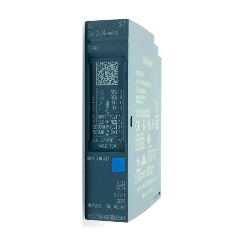
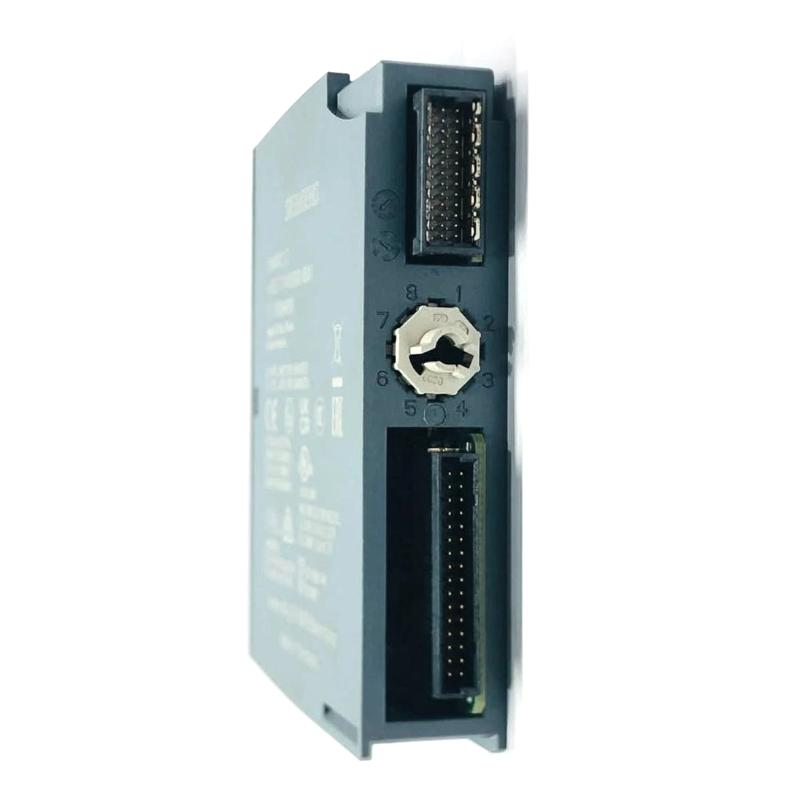
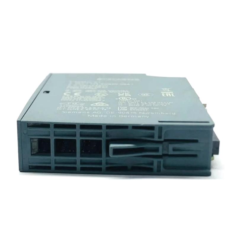
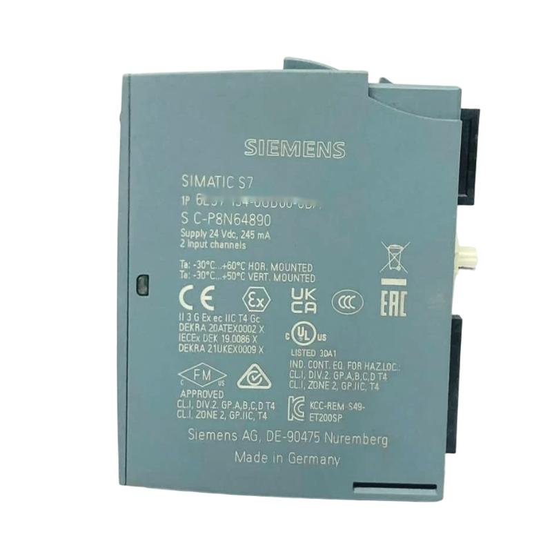
- Siemens
- 6AG1135-6GB00-7BA1
- Analog Output Module
- Germany
- 15 × 73 × 58 mm
- 0.041 kg
- Xiamen, China
- New & In Stock
- T/T, PayPal, Western Union
- 1 Year
- 1-3 Working Days
- DHL, UPS, TNT, FedEx and EMS.
- 24-Hour Service
- COO
- 77
Our advantage

Global Logistics
We have a 10-year logistics and express cooperation agreement, so our products can be shipped to any place in the world.

Brand new and original
Our products are imported in bulk from the place of origin. Because of the cooperative relationship, our products are all original and 100% new.

24-hour service
We provide 7*24 hours service to our customers. We will be there whenever you need us.

Price advantage
All our products are priced very favorably because we have our own warehouse and supply.
| Company Information | |||
| [email protected] | |||
| Mobile | +8615980777398 | ||
| +8615980777398 | |||
| 15980777398 |
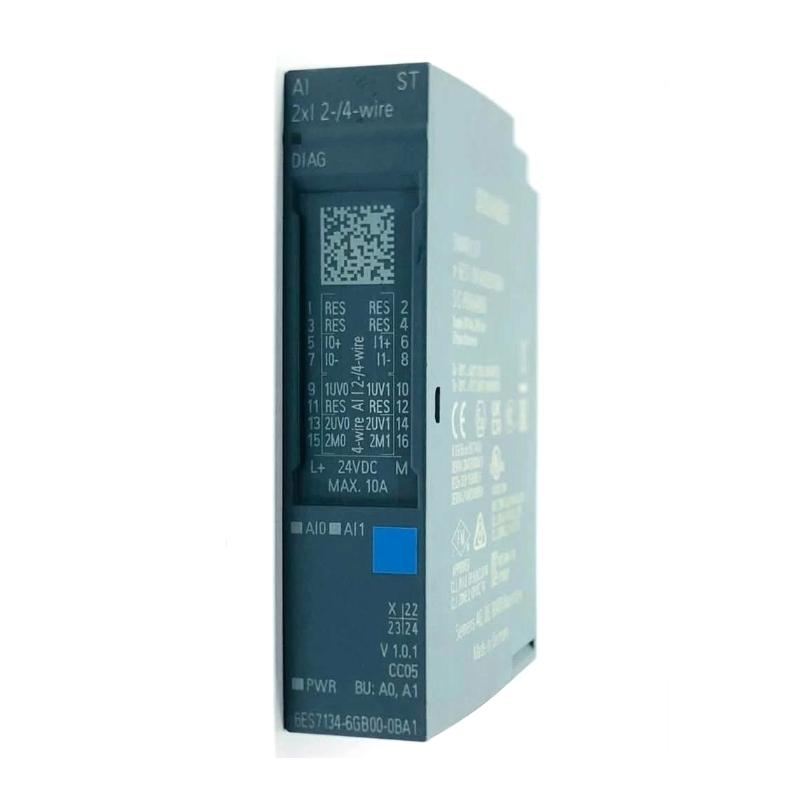
Product Overview
The Siemens 6AG1135-6GB00-7BA1 SIPLUS ET 200S Analog Output Module is an analog output module used to interface a Siemens distributed I/O station with field devices that require continuously variable electrical control signals. It belongs to the SIPLUS range and is intended for industrial automation environments where analog actuator control needs to be integrated into a modular I/O architecture.
Unlike a digital output, which normally provides a simple switching state, an analog output represents a process value or control command over a defined electrical range. This makes the module suitable for applications such as valve control, analog regulators, actuator references, and other process-control functions.
In a typical installation, the PLC calculates the required process value and transfers it through the distributed I/O system. The 6AG1135-6GB00-7BA1 then handles the field-side analog output, allowing the connected device to respond proportionally to the controller’s command.
The module is best used as part of a complete distributed I/O station. Interface hardware, terminal components, power supply, PLC configuration, field wiring, and the receiving actuator all have to be considered when planning an installation or replacement.
Technical Specifications
| Parameter | Specification |
|---|---|
| Manufacturer | Siemens |
| Model | 6AG1135-6GB00-7BA1 |
| Product Family | SIPLUS ET 200 |
| Product Type | Analog Output Module |
| Application | Distributed Analog Output |
| Output Function | Analog Signal Generation |
| Number of Channels | 2 Analog Outputs |
| Module Architecture | Distributed I/O |
| Mounting Width | 15 mm |
| Dimensions | 15 × 73 × 58 mm |
| Weight | 0.041 kg |
Product Features
The 6AG1135-6GB00-7BA1 is intended for applications where analog output signals need to be integrated into a Siemens distributed control architecture.
Key characteristics include:
- SIPLUS distributed I/O analog output module
- Two analog output channels
- Compact modular construction
- Suitable for proportional control applications
- Designed for field-level analog signal transmission
- Suitable for process and machine automation
- Integrates with Siemens PLC-based control systems
- Supports distributed installation concepts
- Suitable for actuator and regulator applications
- SIPLUS product design for demanding industrial environments
- Dimensions of 15 × 73 × 58 mm
- Weight of 0.041 kg
The exact electrical output configuration should always be checked against the connected field device and the engineering configuration before commissioning.
Working Principle
The module converts the controller’s calculated output value into an analog electrical signal for the connected field device.
A typical signal path is:
PLC → Distributed I/O Interface → Analog Output Module → Analog Signal → Field Device
For example, a PLC may calculate a valve command based on process pressure or temperature. Instead of sending a simple ON/OFF instruction, the controller sends a proportional value to the analog output channel.
The output module then generates the corresponding electrical signal. The valve positioner or other receiving device interprets this signal and adjusts its operating state accordingly.
This arrangement separates the control function from the physical signal interface. The PLC handles the control algorithm, scaling, interlocks, and process logic, while the analog output module handles the conversion between the controller’s data and the field-level electrical signal.
When troubleshooting an analog output, engineers should therefore check the PLC value, output configuration, actual measured signal, field wiring, and receiving device separately. A problem at any point in this chain can produce similar symptoms.
Role in a Distributed I/O System
The 6AG1135-6GB00-7BA1 functions as the field-level analog output interface within a distributed Siemens automation system.
A typical architecture can be represented as:
SIMATIC PLC → Distributed I/O Network → I/O Station → 6AG1135-6GB00-7BA1 → Field Actuator
This arrangement allows analog I/O to be located closer to the process equipment rather than bringing every individual signal cable back to the main control cabinet.
Typical field devices can include:
- Control valve positioners
- Analog actuators
- Process regulators
- Speed reference inputs
- Industrial controllers
- Proportional control devices
The module does not independently determine the required process output. That decision remains with the PLC or higher-level control application. Its role is to provide the physical analog output channel required to execute the command at the field level.
Industrial Applications
The module can be used wherever a distributed Siemens control system needs analog output channels for proportional control.
| Application | Typical Use |
|---|---|
| Process Automation | Analog process-control commands |
| Valve Control | Proportional valve positioning |
| Water Treatment | Distributed actuator control |
| Chemical Processing | Analog control-loop outputs |
| Pump Systems | Analog reference signals |
| HVAC Systems | Control of proportional actuators |
| Manufacturing Machinery | Variable actuator commands |
| Utility Systems | Analog equipment regulation |
| Industrial Skids | Local analog field control |
| Control Cabinets | Distributed analog I/O |
The suitability of the module should be evaluated together with the electrical requirements of the receiving device, particularly its input signal type, range, load characteristics, and wiring arrangement.
Installation and Maintenance
The module should be installed as part of a compatible Siemens distributed I/O station. Before replacing an existing analog output module, the complete station architecture should be checked rather than comparing only the module’s physical dimensions.
Recommended installation and maintenance checks include:
- Confirm the complete 6AG1135-6GB00-7BA1 order number.
- Verify compatibility with the existing distributed I/O system.
- Check the interface and terminal arrangement.
- Confirm the required system and field power.
- Verify the receiving device’s analog input requirements.
- Check PLC hardware configuration.
- Confirm channel addressing and scaling.
- Inspect analog signal wiring.
- Check terminal connections for looseness.
- Maintain appropriate shielding and grounding.
- Test each output channel during commissioning.
- Measure the actual electrical output where required.
- Compare the measured signal with the PLC command.
- Review available module diagnostics.
- Check the connected actuator for abnormal response.
When an analog output does not behave as expected, measuring the signal directly at the output terminals is often the fastest diagnostic step. If the measured signal matches the PLC command but the actuator does not respond correctly, the investigation can move toward the field wiring or receiving device.
Related Components
The analog output module normally operates together with several components within the distributed control architecture.
| Component | Function |
|---|---|
| Siemens SIMATIC PLC | Executes the control program |
| Distributed I/O Interface | Connects the I/O station with the controller |
| Terminal Module | Provides field wiring connections |
| Power Supply | Provides required control and field power |
| Industrial Network | Transfers process data between PLC and I/O |
| Analog Signal Cable | Carries the output signal |
| Control Valve Positioner | Converts analog command into valve movement |
| Analog Actuator | Responds proportionally to the output |
| Field Terminal Block | Organizes field wiring |
| Control Cabinet | Houses automation and power components |
The module should be evaluated as one element within this system. Correct communication, power distribution, signal wiring, and field-device configuration are all necessary for reliable analog output operation.
Recommended Related Models
When selecting a replacement or expanding an analog output system, related Siemens modules should be compared according to system generation, signal type, channel count, and installation architecture.
| Model | Product Type | Main Function | Typical Application |
|---|---|---|---|
| Siemens 6AG1135-6GB00-7BA1 | SIPLUS Analog Output Module | Analog field output | Distributed actuator control |
| Siemens 6AG1135-4GB01-2AB0 | SIPLUS ET 200S Analog Output Module | Analog current output | 4–20 mA control applications |
| Siemens 6AG1135-4LB02-7AB0 | SIPLUS ET 200S Analog Output Module | Analog output | Distributed analog control |
| Siemens 6AG1135-4FB01-2AB0 | SIPLUS ET 200S Analog Output Module | Analog voltage output | Voltage-based actuator control |
| Siemens 6AG1135-6HB00-2DA1 | SIPLUS Distributed Analog Output | Analog voltage/current output | Flexible analog applications |
| Siemens 6AG1135-6HD00-7BA1 | SIPLUS Analog Output Module | Multi-channel analog output | Higher-density I/O installations |
For replacement projects, the system family should be confirmed before ordering. ET 200S and ET 200SP components are not interchangeable simply because they perform similar analog I/O functions. Interface modules, terminal technology, mounting, engineering configuration, and addressing can differ between system generations.
Key Advantages
- SIPLUS Siemens distributed analog output module
- Two analog output channels
- Suitable for proportional field control
- Compact modular construction
- Suitable for distributed I/O architectures
- Supports PLC-controlled analog output functions
- Suitable for process and machine automation
- Applicable to valve and actuator control
- Useful for distributed control cabinets
- Suitable for industrial environments
- Dimensions of 15 × 73 × 58 mm
- Weight of 0.041 kg
Technical FAQs
What is the main function of the Siemens 6AG1135-6GB00-7BA1?
The module provides analog output channels within a Siemens distributed I/O system. It takes output values generated by the PLC and makes them available as corresponding analog signals for compatible field devices.
Why is analog output preferable to a digital output for valve control?
A digital output normally provides a switching command, while an analog output can represent a continuously variable setpoint. For a proportional control valve, this allows the PLC to request different operating positions instead of only fully open or fully closed states.
What should be checked when replacing an existing analog output module?
The most important checks are the exact order number, I/O system generation, interface module, terminal arrangement, output signal characteristics, PLC hardware configuration, channel addressing, and the receiving device’s input requirements. Physical dimensions alone are not sufficient for replacement selection.
How can an engineer distinguish a module fault from a field-device problem?
First compare the commanded PLC value with the actual electrical signal measured at the module output. If the module generates the expected signal, inspect the field cable, terminals, grounding, and receiving device. If the measured output itself is incorrect, the PLC configuration and module should then be investigated.