

ProductPRODUCT
Featured products



Contact Us
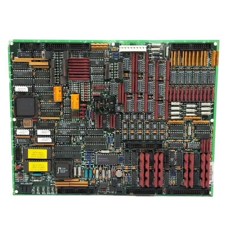
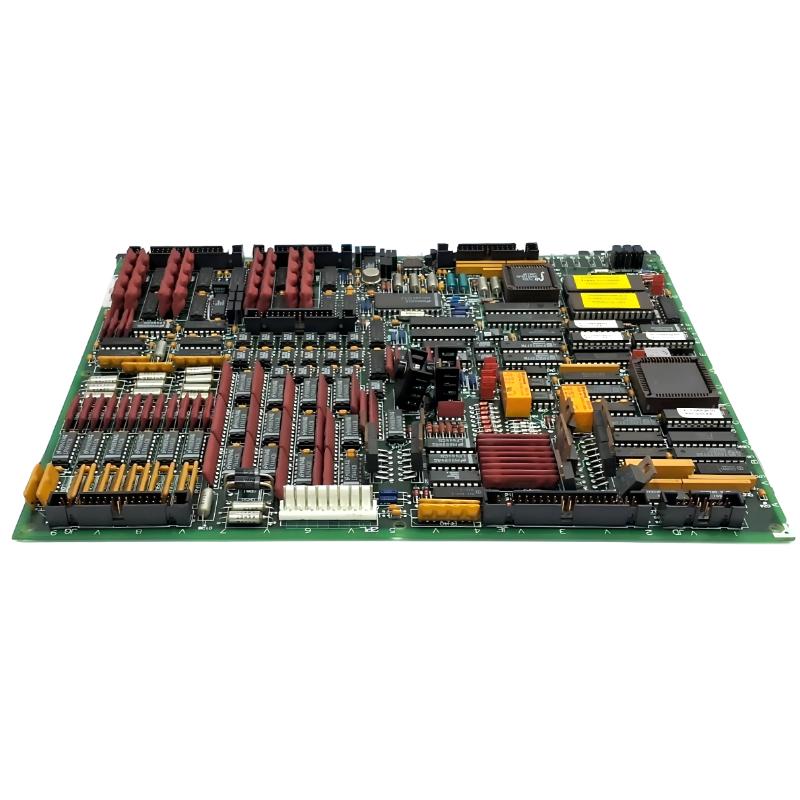
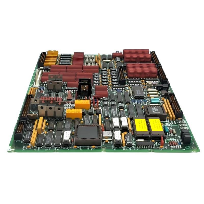
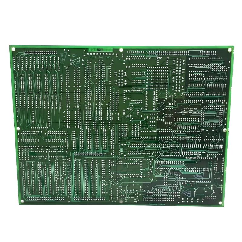
- GE
- DS215TCQFG1AZZ01A DS200TCQAG1BGD
- Analog I/O Board
- USA
- 220 × 160 × 25 mm
- 0.65 kg
- Xiamen, China
- New & In Stock
- T/T, PayPal, Western Union
- 1 Year
- 1-3 Working Days
- DHL, UPS, TNT, FedEx and EMS.
- 24-Hour Service
- COO
- 80
Our advantage

Global Logistics
We have a 10-year logistics and express cooperation agreement, so our products can be shipped to any place in the world.

Brand new and original
Our products are imported in bulk from the place of origin. Because of the cooperative relationship, our products are all original and 100% new.

24-hour service
We provide 7*24 hours service to our customers. We will be there whenever you need us.

Price advantage
All our products are priced very favorably because we have our own warehouse and supply.
| Company Information | |||
| [email protected] | |||
| Mobile | +8615980777398 | ||
| +8615980777398 | |||
| 15980777398 |
Product Overview
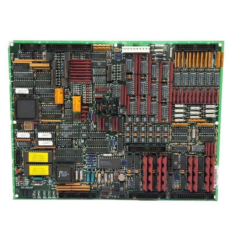
The GE DS215TCQFG1AZZ01A with the associated DS200TCQAG1BGD is an Analog I/O Board designed for compatible GE Mark V Speedtronic turbine control systems. This type of board provides an interface between field-level analog signals and the turbine control architecture, allowing continuously varying process information to be acquired, conditioned, and used by the control system.
Analog I/O hardware is a fundamental part of industrial turbine automation because many important operating parameters cannot be represented simply as ON/OFF signals. Temperature, pressure, flow, valve position, actuator feedback, fuel-related measurements, vibration-related signals, and other process variables may require analog signal processing.
The DS200TCQAG1BGD belongs to the TCQA analog I/O family used within the GE Mark V control architecture. Its primary role is to support the processing and conditioning of analog signals associated with turbine monitoring and control functions.
The configured assembly designation DS215TCQFG1AZZ01A should be retained together with the board-level identification DS200TCQAG1BGD when identifying replacement hardware. For legacy control systems, the complete identification is important because related GE Mark V boards can have different revisions and configurations.
The specified physical dimensions of this product are 220 × 160 × 25 mm, with a specified weight of 0.65 kg.
The board is intended to operate as part of a larger turbine control architecture rather than as a standalone controller. It works with associated terminal boards, control processors, field instrumentation, power supplies, and other Mark V I/O hardware to provide a complete signal path between the physical turbine process and the control logic.
Technical Specifications
| Parameter | Details |
|---|---|
| Manufacturer | GE General Electric |
| Model | DS215TCQFG1AZZ01A |
| Associated Board | DS200TCQAG1BGD |
| Product Type | Analog I/O Board |
| Functional Family | TCQA |
| System Family | GE Mark V Speedtronic |
| Functional Description | Analog Input/Output Board |
| Primary Function | Analog signal scaling, conditioning and interfacing |
| Signal Type | Analog field signals |
| Application | Turbine control and process monitoring |
| Installation | Mark V control cabinet / I/O rack |
| Control Architecture | Mark V turbine control system |
| Interface Role | Field instrumentation to control system |
| Dimensions | 220 × 160 × 25 mm |
| Weight | 0.65 kg |
| Industrial Environment | Industrial turbine automation |
| Service Application | Maintenance, replacement and system restoration |
Function and Working Principle
The main function of the DS200TCQAG1BGD is to provide analog signal processing within the compatible GE Mark V turbine control system.
Field instrumentation converts physical parameters into electrical signals. These signals are then transferred through field wiring and terminal interfaces to the Mark V I/O hardware. The TCQA board processes the relevant analog signals before the information is used by the control system.
A simplified analog input path can be represented as:
Field Sensor → Field Wiring → Terminal Board → TCQA Analog I/O Board → Control Processor
For an analog output, the signal path can operate in the opposite direction:
Control Processor → TCQA Analog Output → Terminal Board → Actuator or Field Device
This arrangement allows the turbine controller to continuously monitor process conditions and generate variable control commands.
Depending on the turbine configuration, the TCQA architecture can be associated with signals such as:
- 4–20 mA process inputs
- 4–20 mA control outputs
- Voltage inputs
- Thermocouple signals
- LVDT and LVDR position feedback
- Servo-valve signals
- Pulse-rate inputs
- Vibration signals
- Generator and line-related signals
- Relay-driver-related outputs
The exact signal assignment is determined by the individual Mark V turbine configuration.
Analog Signal Scaling and Conditioning
One of the most important functions of an analog I/O board is to ensure that incoming field signals can be correctly interpreted by the turbine control system.
Field devices can produce different types of electrical signals. A pressure transmitter, for example, may generate a variable current signal corresponding to process pressure. A position transducer can produce a signal representing actuator movement, while a thermocouple generates a temperature-dependent voltage.
The analog I/O architecture provides the appropriate interface between these field signals and the control system.
Signal-processing functions can include:
- Analog signal scaling
- Signal conditioning
- Filtering
- Input interface processing
- Output signal generation
- Position feedback processing
- Current signal interfacing
- Voltage signal interfacing
- Temperature signal processing
- Pulse-related signal processing
Correct signal conditioning is important because the control processor must receive stable and correctly scaled process information.
If the signal entering the control system is incorrect, the controller may calculate an incorrect process condition. Therefore, the analog I/O board has a direct relationship with control-system measurement quality.
Role in Industrial Control Systems
The GE DS215TCQFG1AZZ01A DS200TCQAG1BGD is an interface component within the Mark V turbine control architecture.
The board does not replace the main turbine controller. Instead, it provides the signal-processing infrastructure required for communication between the physical process and the control logic.
A typical closed-loop turbine control sequence can be represented as:
Physical Process → Sensor → Analog I/O → Control Processor → Control Algorithm → Analog Output → Actuator → Physical Process
For example, a turbine actuator may require continuous position feedback. A position sensor detects the actuator position and generates an electrical signal. The signal is transmitted through the appropriate terminal interface to the analog I/O hardware. The controller then evaluates the actual position and compares it with the desired operating point.
If the position is different from the desired value, the controller can generate an appropriate output command to the actuator.
This continuous feedback process is fundamental to stable turbine operation.
RST Analog I/O Architecture
The TCQA family is associated with the analog I/O portion of the Mark V RST architecture.
In a redundant Mark V control configuration, I/O information can be associated with the R, S, and T control cores. This architecture allows the turbine control system to process signals through multiple control paths while maintaining the overall control strategy.
Analog I/O boards can receive signals from terminal boards located in the respective I/O cores. Depending on the system design, these signals may include measurements related to temperature, pressure, position, vibration, fuel flow, generator conditions, and other turbine operating parameters.
The general architecture can be summarized as:
Field Devices → Terminal Boards → TCQA I/O Hardware → Mark V Control Cores → Operator Interface
The exact arrangement depends on the specific turbine and control-panel design.
Typical Analog Signals
| Signal Category | Typical Example | Purpose |
|---|---|---|
| 4–20 mA Input | Pressure transmitter | Continuous process measurement |
| 4–20 mA Output | Control reference | Variable equipment control |
| Voltage Input | Process measurement | Analog monitoring |
| Thermocouple | Temperature measurement | Thermal monitoring |
| LVDT | Valve or actuator position | Position feedback |
| LVDR | Position feedback | Actuator monitoring |
| Pulse Rate | Rotational measurement | Speed-related control |
| Vibration | Equipment vibration | Machine condition monitoring |
| Generator Signal | Electrical measurement | Generator control |
| Line Signal | Electrical system measurement | Power-system control |
These categories describe typical functions associated with the TCQA architecture. The actual channel assignment must be confirmed from the turbine-specific configuration.
Industrial Applications
The GE DS215TCQFG1AZZ01A DS200TCQAG1BGD is intended for compatible GE Mark V turbine control applications.
Typical industrial environments include:
- Gas turbine power generation
- Steam turbine control
- Combined-cycle power plants
- Industrial turbine systems
- Cogeneration facilities
- Mechanical drive turbine systems
- Compressor drive applications
- Petrochemical process facilities
- Industrial process automation
- Legacy GE Speedtronic control installations
In these environments, the board supports the acquisition and processing of analog information required for turbine monitoring and automatic control.
It is particularly relevant to maintenance programs for legacy Mark V systems where the original control architecture continues to operate and replacement I/O hardware is required.
Compatible System Components
The DS200TCQAG1BGD is normally used as part of a larger Mark V system. Its operation depends on appropriate interaction with field interfaces, terminal boards, processors, power supplies, and other I/O hardware.
| Component | Type | Typical Function |
|---|---|---|
| DS215TCQFG1AZZ01A | Configured Assembly | Configured Mark V I/O hardware |
| DS200TCQAG1BGD | Analog I/O Board | Analog signal processing |
| TCQA Board Family | Analog I/O | Signal scaling and conditioning |
| TBQA | Terminal Board | Thermocouple and field signal interface |
| TBQB | Terminal Board | Vibration-related signal interface |
| TBQC | Terminal Board | Analog and position signal interface |
| TCQC | I/O Interface Board | Generator, line and pulse-related interface |
| TCPS | Power Supply Board | Provides control-system power |
| STCA | Control / Interface Board | Receives selected I/O information |
| Mark V Control Processor | Control Hardware | Executes turbine control logic |
| Field Transmitters | Instrumentation | Measure process conditions |
| Position Sensors | Feedback Devices | Provide actuator feedback |
| Control Valves | Final Control Elements | Regulate turbine processes |
The exact combination of components depends on the turbine model and the engineering configuration of the Mark V control panel.
Installation and System Integration
Correct installation is essential when replacing an analog I/O board because incorrect connector placement, wiring, or configuration can affect multiple process signals.
Before removing an existing DS200TCQAG1BGD board, maintenance personnel should document its complete configuration.
A general installation sequence includes:
- Place the turbine control system into the approved maintenance state.
- Follow site lockout and electrical isolation procedures.
- Verify that relevant control power has been removed.
- Identify the installed board.
- Record the DS215TCQFG1AZZ01A assembly number.
- Record the DS200TCQAG1BGD board number.
- Document the board location.
- Record all connector positions.
- Label ribbon cables before removal.
- Record jumper positions and configuration settings.
- Inspect the replacement board for physical damage.
- Check all connectors for contamination or damage.
- Install the replacement board in the correct rack position.
- Reconnect the cables to their original locations.
- Verify connector engagement.
- Check grounding and shielding.
- Restore power according to the approved maintenance procedure.
- Check board status and diagnostic indications.
- Verify analog input values.
- Verify required analog output functions.
- Complete the required commissioning checks.
The actual procedure should always be adapted to the installed Mark V cabinet and turbine-specific engineering documentation.
Connector and Cable Considerations
Analog I/O boards use multiple connectors to exchange signals with other Mark V boards and terminal interfaces.
Ribbon cables should be handled carefully during maintenance. Pulling directly on the ribbon portion of a cable can separate the cable from its connector or damage individual conductors.
Before reinstalling cables, technicians should inspect:
- Connector alignment
- Connector locking features
- Ribbon cable condition
- Contact condition
- Signs of contamination
- Mechanical damage
- Correct connector orientation
A defective cable or connector can produce symptoms that resemble an analog I/O board failure. Therefore, cable inspection should be part of the diagnostic process.
Jumper and Hardware Configuration
Mark V analog I/O boards can contain configurable hardware resources. Jumper positions may influence certain board functions, so they should be recorded before removing the existing board.
During replacement, technicians should compare:
- Board revision
- Jumper positions
- Connector arrangement
- Programmable-device configuration
- Associated terminal boards
- I/O channel configuration
- Control-core location
If a replacement board has a different hardware revision, compatibility should be verified before installation rather than assuming that boards with similar model numbers are interchangeable.
Maintenance and Troubleshooting
Troubleshooting the DS200TCQAG1BGD should begin by determining the scope of the problem.
If one signal is abnormal, the technician should investigate the individual field device and signal path. If many channels fail simultaneously, common power, connector, terminal, or board-level causes should be investigated first.
| Observed Condition | Possible Area to Check |
|---|---|
| One analog input reads zero | Sensor, transmitter, field wiring, terminal connection or input channel |
| Analog value is unstable | Shielding, grounding, interference or transmitter condition |
| Analog value is incorrect | Sensor calibration, scaling, wiring or input circuitry |
| Multiple analog channels fail | Power supply, common wiring, terminal board or board hardware |
| Analog output does not respond | Control command, output channel, wiring or actuator |
| Output is unstable | Output circuitry, load, wiring or grounding |
| Intermittent signal | Connector, ribbon cable, terminal or field device |
| Board diagnostic indication is abnormal | Power, configuration or board-level hardware |
| Generator or line signal is abnormal | Associated interface, wiring or TCQA circuitry |
| Position feedback is incorrect | LVDT/LVDR, wiring, terminal interface or input circuitry |
A practical diagnostic path is:
Field Device → Wiring → Terminal Board → TCQA Board → Associated I/O Hardware → Control Processor → Operator Interface
This signal-tracing method helps determine whether the problem is located in the field instrumentation, wiring, terminal interface, board, or control system.
Diagnosing 4–20 mA Input Problems
4–20 mA signals are widely used for industrial process measurements because they can provide reliable analog transmission over relatively long field cable runs.
When a 4–20 mA measurement is incorrect, the first step is to determine whether the transmitter is generating the expected electrical signal.
If the transmitter output is correct but the control system displays an incorrect value, the investigation should continue through the field wiring, terminal board, TCQA input channel, and system scaling.
If the transmitter itself produces an incorrect output, the field device or its power supply may be responsible.
This distinction is important because replacing the analog board without verifying the field signal can result in unnecessary maintenance.
Diagnosing Analog Output Problems
When an analog output does not produce the expected response, the technician should first determine whether the control system is generating the correct command.
The following points should be checked:
- Control command value
- Output channel status
- Board configuration
- Output wiring
- Terminal-board connection
- Field-device input
- Actuator condition
If the control command is correct but the electrical output is missing, the investigation can move toward the output channel and associated circuitry.
If the output reaches the field device but the actuator does not respond, the problem may be located in the actuator or final control element rather than the TCQA board.
Diagnosing LVDT and LVDR Signals
Position feedback is important in turbine control systems because actuators and servo valves often require accurate position information.
LVDT and LVDR devices can provide position-related feedback to the analog I/O system.
If the indicated position is incorrect, technicians should check:
- Position sensor condition
- Mechanical sensor installation
- Sensor wiring
- Terminal connections
- Excitation signals
- Signal conditioning
- TCQA input circuitry
- Control-system scaling
A position-feedback fault can therefore originate from either the mechanical sensor or the electronic signal-processing path.
Thermocouple Signal Troubleshooting
Temperature measurements are critical in turbine control because excessive or abnormal temperatures can affect equipment performance and protection functions.
Thermocouple signals require correct wiring and appropriate signal processing.
If a temperature value is abnormal, possible causes include:
- Damaged thermocouple
- Incorrect polarity
- Broken field wiring
- Loose terminal connections
- Cold-junction compensation issues
- Electrical interference
- Input-channel problems
- Incorrect system configuration
An independent temperature measurement can be useful when determining whether the problem originates from the field sensor or the control-system input path.
Common Causes of Analog I/O Problems
Potential causes of problems associated with the DS215TCQFG1AZZ01A DS200TCQAG1BGD include:
- Field transmitter failure
- Damaged signal wiring
- Loose terminals
- Damaged ribbon cables
- Incorrect connector placement
- Incorrect jumper settings
- Power supply problems
- Electrical interference
- Grounding problems
- Sensor degradation
- Terminal-board faults
- Board-level component failure
- Incorrect configuration
- Hardware revision mismatch
A systematic diagnostic procedure is recommended before replacing the board.
Replacement Considerations
When sourcing a replacement for the DS200TCQAG1BGD, the complete identification should be checked carefully.
Important information includes:
- DS215TCQFG1AZZ01A
- DS200TCQAG1BGD
- TCQA functional family
- Hardware revision
- Board location
- Connector arrangement
- Jumper configuration
- Associated terminal boards
- Control-core configuration
- Analog channel assignment
Related TCQA boards can have different revisions. A board that appears physically similar may not have exactly the same configuration or revision.
For this reason, the complete part number should be used when selecting replacement hardware rather than relying only on the general description “Analog I/O Board.”
Recommended Alternative Models
The following GE Mark V models are related analog I/O or control-system components that may be considered for comparison and spare-parts planning. They should not automatically be treated as direct substitutes for the DS200TCQAG1BGD.
| Model | Type | Key Feature | Application |
|---|---|---|---|
| DS215TCQFG1AZZ01A | Configured Analog I/O Assembly | Configured TCQA hardware | GE Mark V turbine control |
| DS200TCQAG1BGD | Analog I/O Board | Analog signal scaling and conditioning | Mark V analog I/O |
| DS200TCQAG1BGE | Analog I/O Board | Related TCQA revision | Mark V turbine control |
| DS200TCQAG1BDC | Analog I/O Board | TCQA analog interface | Legacy Mark V systems |
| DS200TCQAG1BEC | Analog I/O Board | Related analog I/O configuration | GE Speedtronic systems |
| DS200TCQAG1BHF | Analog I/O Board | Alternative TCQA revision | Legacy turbine automation |
| DS215TCQBG1BZZ01A | Extended Analog I/O Assembly | Expanded analog interface | Mark V RST architecture |
| DS200TCQBG1BBA | Extended Analog I/O Board | Additional analog I/O capacity | GE Mark V systems |
Replacement recommendation: The preferred replacement should be an exact match for the complete DS215TCQFG1AZZ01A DS200TCQAG1BGD identification. Related TCQA or TCQB models should only be considered after checking the hardware revision, system configuration, connector arrangement, terminal-board connections, and required I/O functions.
Key Advantages
- Designed for compatible GE Mark V Speedtronic turbine control systems
- Provides analog input and output interface capability
- Supports analog signal scaling and conditioning
- Interfaces field instrumentation with turbine control logic
- Supports continuously variable process measurements
- Can support analog control outputs
- Works with associated Mark V terminal boards
- Supports turbine monitoring and closed-loop control
- Suitable for legacy GE turbine automation maintenance
- Provides an important interface between field-level signals and control processors
Technical FAQs
What is the GE DS215TCQFG1AZZ01A?
The GE DS215TCQFG1AZZ01A is a configured assembly associated with the TCQA analog I/O function in the GE Mark V turbine control architecture. The associated board identification is DS200TCQAG1BGD.
What is the DS200TCQAG1BGD?
The DS200TCQAG1BGD is an Analog I/O Board associated with the GE Mark V Speedtronic turbine control system. It provides analog signal processing, scaling, conditioning, and interfacing functions.
What is the main function of the DS200TCQAG1BGD?
Its main function is to interface analog field signals with the Mark V control architecture and support the processing of continuously variable turbine measurements and control signals.
What are the dimensions of the board?
The specified dimensions are 220 × 160 × 25 mm.
What is the weight of the DS200TCQAG1BGD?
The specified weight is 0.65 kg.
What types of signals can the TCQA board handle?
Depending on the system configuration, the TCQA architecture can be associated with 4–20 mA inputs and outputs, voltage signals, thermocouples, LVDT/LVDR position feedback, vibration inputs, pulse signals, servo-related signals, and generator or line signals.
Where is the DS200TCQAG1BGD used?
It is associated with GE Mark V turbine control systems used in gas turbine, steam turbine, combined-cycle, and other industrial turbine applications.
What components work with this analog I/O board?
Typical associated components include terminal boards, TCQA and TCQB I/O hardware, Mark V control processors, power supply boards, field transmitters, temperature sensors, position sensors, actuators, control valves, and operator-interface equipment.
What causes an analog input to display an incorrect value?
Possible causes include a faulty field transmitter, damaged wiring, loose terminals, electrical interference, grounding problems, incorrect scaling, terminal-board faults, or defective analog input circuitry.
Should the board be replaced when an analog signal fails?
Not immediately. The field device, wiring, terminal connection, configuration, and I/O channel should be checked first. Board replacement should be considered after the fault has been isolated to the board.
Can DS200TCQAG1BGE replace DS200TCQAG1BGD?
These are related TCQA analog I/O configurations, but they should not automatically be considered interchangeable. Hardware revision, system configuration, connector arrangement, and signal assignments should be verified before substitution.
Why is the complete DS215 and DS200 identification important?
The DS215 assembly designation and DS200 board designation provide more precise identification of the configured hardware. This is particularly important when maintaining legacy Mark V systems with multiple related board revisions.
How should an analog I/O fault be diagnosed?
The most effective approach is to trace the signal from the field device through the wiring and terminal board to the TCQA board and then toward the control processor. This helps distinguish field-device faults from board-level problems.
Conclusion
The GE DS215TCQFG1AZZ01A DS200TCQAG1BGD Analog I/O Board is an important interface component for compatible GE Mark V Speedtronic turbine control systems. Its role is to process and condition analog information between field instrumentation and the turbine control architecture.
Analog I/O functions are essential in turbine automation because important operating parameters such as pressure, temperature, position, flow, vibration, and other process values are continuously variable. The TCQA architecture allows these signals to be incorporated into turbine monitoring and closed-loop control functions.
The specified dimensions of the product are 220 × 160 × 25 mm, with a specified weight of 0.65 kg. For maintenance and replacement purposes, the complete identification DS215TCQFG1AZZ01A DS200TCQAG1BGD should be retained.
For engineers and maintenance teams working with legacy GE Mark V equipment, correct hardware identification is particularly important. Board revision, connector arrangement, jumper configuration, terminal-board connections, control-core location, and turbine-specific I/O assignments should all be verified before installation.
When correctly integrated with the surrounding Mark V control architecture, the GE DS215TCQFG1AZZ01A DS200TCQAG1BGD provides a practical analog interface for process monitoring and turbine control. Its role in signal scaling, conditioning, and field-device interfacing makes it a valuable component for maintaining established GE Speedtronic turbine automation systems.