

ProductPRODUCT
Featured products








Contact Us
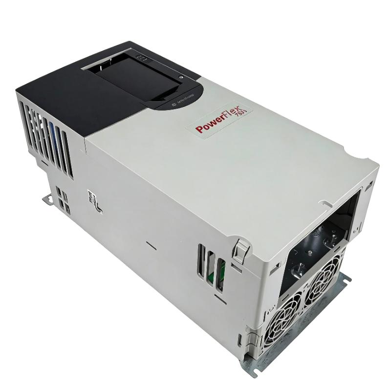
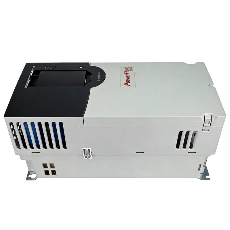
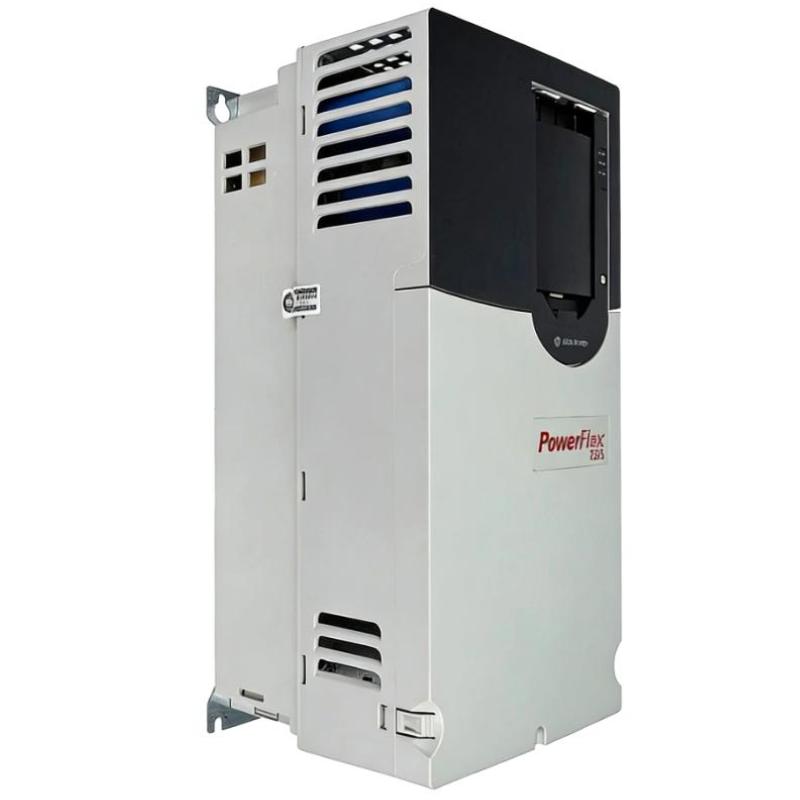
- Allen Bradley
- 20F11RC2P1JA0NNNNN
- PowerFlex AC Drive
- USA
- 450 x 360 x 130 mm
- 6kg
- Xiamen, China
- New & In Stock
- T/T, PayPal, Western Union
- 1 Year
- 1-3 Working Days
- DHL, UPS, TNT, FedEx and EMS.
- 24-Hour Service
- COO
- 48
Our advantage

Global Logistics
We have a 10-year logistics and express cooperation agreement, so our products can be shipped to any place in the world.

Brand new and original
Our products are imported in bulk from the place of origin. Because of the cooperative relationship, our products are all original and 100% new.

24-hour service
We provide 7*24 hours service to our customers. We will be there whenever you need us.

Price advantage
All our products are priced very favorably because we have our own warehouse and supply.
| Company Information | |||
| [email protected] | |||
| Mobile | +8615980777398 | ||
| +8615980777398 | |||
| 15980777398 |
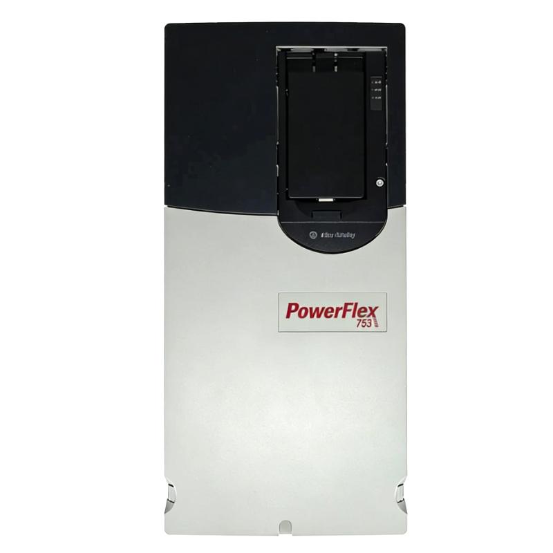
Allen-Bradley 20F11RC2P1JA0NNNNN — PowerFlex 753 0.75 kW AC Drive | Detailed Specifications, Product Introduction, Applications, Advantages and Related Models
1. Product Overview
The Allen-Bradley 20F11RC2P1JA0NNNNN is a PowerFlex 753 AC Drive designed for three-phase industrial motor control.
It is a 400 VAC-class, Frame 1 variable frequency drive with a 2.1 A normal-duty output rating and 0.75 kW normal-duty power rating.
For heavy-duty operation, the applicable rating is approximately 1.5 A and 0.37 kW.
The drive uses forced-air cooling, an IP20 / NEMA/UL open-type enclosure, embedded I/O, EMC filtering, an internal dynamic-braking transistor, and an AC input with precharge and DC terminals.
One of the most important details of this exact catalog number is the JA configuration. The common-mode capacitor jumper is installed, which distinguishes this model from the closely related 20F11RC2P1AA0NNNNN configuration.
The product is intended for industrial machines where a small three-phase motor needs adjustable speed, controlled acceleration and deceleration, basic drive I/O, and integration into a larger automation system.
2. Basic Product Information
| Item | Specification |
|---|---|
| Model / Catalog Number | 20F11RC2P1JA0NNNNN |
| Brand | Allen-Bradley |
| Product Family | PowerFlex |
| Product Series | PowerFlex 753 |
| Product Type | Industrial AC Variable Frequency Drive |
| Drive Type | Air-Cooled AC Drive |
| Voltage Class | 400 VAC |
| Nominal Supply Voltage | 415 VAC |
| Supply Voltage Range | 380–480 VAC |
| Input Phase | 3-phase |
| Output Phase | 3-phase |
| Normal-Duty Current | 2.1 A |
| Normal-Duty 1-Minute Current | Approx. 2.3 A |
| Normal-Duty 3-Second Current | Approx. 3.2 A |
| Normal-Duty Power | 0.75 kW |
| Normal-Duty Motor Class | Approx. 1 HP |
| Heavy-Duty Current | Approx. 1.5 A |
| Heavy-Duty 1-Minute Current | Approx. 1.65 A |
| Heavy-Duty 3-Second Current | Approx. 2.25 A |
| Heavy-Duty Power | 0.37 kW |
| Heavy-Duty Motor Class | Approx. 0.5 HP |
| Frame Size | Frame 1 |
| Cooling | Forced Air |
| Enclosure | IP20 / NEMA/UL Open Type |
| EMC Filtering | Yes |
| CM Capacitor Jumper | Installed |
| Dynamic Braking | Internal DB Transistor |
| Internal Braking Resistor | No |
| External Braking Resistor | Supported |
| Embedded I/O | Yes |
| HIM | Blank / No HIM |
| Input Type | AC Input with Precharge |
| DC Terminals | Yes |
| Mounting | Panel / Cabinet |
| Approx. Height | 400.5 mm |
| Approx. Width | 110 mm |
| Approx. Depth | 211 mm |
| Approx. Weight | 6.0 kg |
The core electrical specification is the 2.1 A normal-duty output rating.
This is a relatively small drive from a motor-power perspective, but it still belongs to the PowerFlex 753 platform, so it is intended for applications where a more capable industrial drive architecture is useful.
3. Detailed Electrical Parameters
| Parameter | Specification |
|---|---|
| Catalog Number | 20F11RC2P1JA0NNNNN |
| Product Series | PowerFlex 753 |
| Drive Type | AC Variable Frequency Drive |
| Input Voltage Class | 400 VAC |
| Nominal Input Voltage | 415 VAC |
| Supply Voltage | 380–480 VAC class |
| Input Frequency | 50/60 Hz |
| Input Phase | 3-phase |
| Output Phase | 3-phase |
| Normal-Duty Continuous Current | 2.1 A |
| Normal-Duty 1-Minute Current | Approx. 2.3 A |
| Normal-Duty 3-Second Current | Approx. 3.2 A |
| Normal-Duty Power | 0.75 kW |
| Normal-Duty Motor Rating | Approx. 1 HP |
| Heavy-Duty Continuous Current | Approx. 1.5 A |
| Heavy-Duty 1-Minute Current | Approx. 1.65 A |
| Heavy-Duty 3-Second Current | Approx. 2.25 A |
| Heavy-Duty Power | 0.37 kW |
| Heavy-Duty Motor Rating | Approx. 0.5 HP |
| Frame | Frame 1 |
| Cooling Method | Forced Air |
| Enclosure | Open Type |
| Protection Rating | IP20 |
| EMC Filter | Yes |
| CM Capacitor Jumper | Installed |
| Dynamic-Braking Transistor | Yes |
| Internal Braking Resistor | No |
| External Braking Resistor | Supported |
| Embedded I/O | Yes |
| HIM | Blank / No HIM |
| AC Input with Precharge | Yes |
| DC Terminals | Yes |
| Approx. Height | 400.5 mm |
| Approx. Width | 110 mm |
| Approx. Depth | 211 mm |
| Approx. Weight | 6.0 kg |
The normal-duty and heavy-duty values are important because the usable motor size changes according to the application duty.
For normal-duty operation, the drive is rated at 0.75 kW.
For heavy-duty operation, the applicable motor rating is approximately 0.37 kW.
The exact motor nameplate current should always be checked before final selection.
4. Normal-Duty and Heavy-Duty Ratings
| Duty Mode | Continuous Current | 1-Minute Current | 3-Second Current | Power Rating | Approx. HP |
|---|---|---|---|---|---|
| Normal Duty | 2.1 A | 2.3 A | 3.2 A | 0.75 kW | 1 HP |
| Heavy Duty | 1.5 A | Approx. 1.65 A | Approx. 2.25 A | 0.37 kW | 0.5 HP |
This difference is important when the motor is subject to high starting torque, frequent acceleration, or other demanding operating conditions.
A 0.75 kW motor should therefore not automatically be assumed to be suitable for every possible application.
If the machine is a high-torque or high-overload application, the heavy-duty rating needs to be considered.
5. Brand and Product Series
| Category | Information |
|---|---|
| Brand | Allen-Bradley |
| Product Family | PowerFlex |
| Product Series | PowerFlex 753 |
| Product Category | Industrial AC Drives |
| Product Type | Variable Frequency Drive |
| Main Function | AC Motor Speed and Torque Control |
| Voltage Class | 400 VAC |
| Frame | Frame 1 |
| Cooling | Forced Air |
| Enclosure | IP20 Open Type |
| Typical Motor Size | 0.75 kW normal duty |
| Typical Installation | Industrial Electrical Cabinet |
The PowerFlex 753 series is designed for industrial motor-control applications where variable-speed operation, programmable acceleration and deceleration, drive diagnostics, I/O integration and flexible control are required.
The series covers a broad range of motor sizes.
That makes it particularly useful for machine builders that want to keep a consistent drive platform across different machines or across different motors within the same machine.
6. Product Introduction
The 20F11RC2P1JA0NNNNN functions as the electronic interface between an industrial controller and a three-phase AC motor.
A typical arrangement is:
PLC / Machine Controller
↓
Speed / Start / Stop Command
↓
PowerFlex 753 Drive
↓
Three-Phase AC Motor
↓
Gearbox / Conveyor / Pump / Fan / Machine Mechanism
The drive converts the incoming electrical power into a controlled motor output.
Instead of simply switching the motor between full speed and stopped, the drive can regulate the motor’s operating frequency and voltage.
This allows the machine to operate at different speeds.
For a conveyor, the motor might run slowly during loading and faster during normal production.
For a pump, the speed can be adjusted according to process demand.
For a fan, the motor speed can be changed according to airflow requirements.
For a packaging machine, the motor can accelerate and decelerate according to the production cycle.
7. 0.75 kW Normal-Duty Capacity
The 0.75 kW normal-duty rating makes this model suitable for many small industrial motors.
Although 0.75 kW is relatively small compared with larger industrial drive ratings, motors in this range are common in automation equipment.
Typical examples include:
- Small conveyors
- Rollers
- Feeders
- Fans
- Small blowers
- Circulation pumps
- Small packaging mechanisms
- Auxiliary machine motors
- Product-transfer systems
The important point is that motor size alone does not determine whether a drive is useful.
A small motor may still require precise speed control, controlled acceleration, controlled stopping and integration with a PLC.
8. 400 VAC Three-Phase Design
The drive is intended for the 400 VAC three-phase class.
A nominal industrial supply of approximately 415 VAC falls naturally within this voltage class.
The typical supply range is approximately 380–480 VAC, subject to the actual installation and applicable drive requirements.
This makes the drive suitable for many industrial facilities using 400 V or 415 V three-phase electrical systems.
Before installation, the following should be checked:
- Incoming voltage
- Number of phases
- Motor voltage
- Motor current
- Motor frequency
- Grounding arrangement
- Machine duty cycle
9. Frame 1 Mechanical Design
The drive uses a Frame 1 enclosure.
Frame 1 is the smallest standard mechanical frame used across many PowerFlex 753 configurations.
Approximate dimensions are:
400.5 mm H × 110 mm W × 211 mm D
The approximate drive weight is:
6.0 kg
The relatively narrow 110 mm width can be useful in compact control cabinets.
The cabinet designer should still allow additional room around the drive for wiring, ventilation and maintenance.
10. Dimensions and Weight
| Mechanical Parameter | Specification |
|---|---|
| Model | 20F11RC2P1JA0NNNNN |
| Frame Size | Frame 1 |
| Height | 400.5 mm |
| Width | 110 mm |
| Depth | 211 mm |
| Approx. Weight | 6.0 kg |
| Enclosure | IP20 / Open Type |
| Cooling | Forced Air |
| Mounting | Panel / Cabinet |
| Installation Orientation | Vertical |
The 6.0 kg figure represents the approximate Frame 1 drive weight.
Actual shipping weight can be higher because packaging and accessories are not the same as the bare drive assembly.
For cabinet engineering, the 6.0 kg drive weight is the more useful mechanical figure.
11. Forced-Air Cooling
The drive uses forced-air cooling.
The internal power electronics generate heat during normal operation.
The cooling system moves air through the drive and transfers heat away from the power section.
For reliable operation, the surrounding cabinet should provide sufficient airflow.
The following factors are particularly important:
- Cabinet temperature
- Ambient temperature
- Airflow
- Fan condition
- Dust accumulation
- Heat from adjacent equipment
- Cabinet ventilation
If several drives are installed in one enclosure, the total heat load should be considered.
12. IP20 Open-Type Construction
The drive uses an IP20 open-type enclosure.
This means it is intended to be installed inside a suitable electrical cabinet or enclosure.
The drive itself should not be treated as a sealed outdoor product.
The surrounding enclosure should provide the required protection against:
- Water
- Dust
- Oil mist
- Metal particles
- Chemicals
- Excessive humidity
- Mechanical impact
This type of construction is common in industrial control cabinets.
13. EMC Filtering
The 20F11RC2P1JA0NNNNN uses an EMC-filtered configuration.
A variable-frequency drive switches its output electronically at high frequency.
That switching action can generate electromagnetic noise.
The EMC filtering arrangement helps control certain conducted disturbances.
However, the quality of the overall installation remains extremely important.
A good installation should consider:
- Grounding
- Cabinet bonding
- Motor cable routing
- Control cable routing
- Cable shielding
- Separation between power and control cables
- Correct termination
The EMC filter is therefore only one part of the complete EMC design.
14. Common-Mode Capacitor Jumper Installed
The JA portion of the catalog number is especially important.
For:
20F11RC2P1JA0NNNNN
the common-mode capacitor jumper is installed.
The closely related AA version:
20F11RC2P1AA0NNNNN
has the common-mode capacitor jumper removed.
| Model | CM Capacitor Jumper |
|---|---|
| 20F11RC2P1JA0NNNNN | Installed |
| 20F11RC2P1AA0NNNNN | Removed |
This is not simply a cosmetic catalog-number difference.
The common-mode capacitor configuration affects the drive’s relationship with the electrical system and grounding arrangement.
When replacing a drive, the complete catalog number should therefore be checked carefully.
15. Dynamic-Braking Transistor
The model includes an internal dynamic-braking transistor.
This allows the drive to control an external braking resistor when the application requires additional braking capability.
During motor deceleration, the motor can return energy toward the drive’s DC bus.
This regenerative energy can cause the DC-bus voltage to rise.
A braking resistor dissipates the excess energy as heat.
The internal braking transistor provides the switching function needed to control that resistor.
Potential applications include:
- Small conveyors
- Packaging machinery
- Rollers
- Feed mechanisms
- Rapid-cycle machines
- Material-transfer equipment
The braking resistor itself is not part of the standard drive.
It needs to be selected according to the actual inertia, stopping time and braking duty.
16. Embedded I/O
The drive includes embedded I/O.
This is useful because basic machine signals can be handled without necessarily adding a separate external I/O interface for every function.
Depending on the machine architecture, typical signals can include:
- Start
- Stop
- Enable
- Direction
- Speed reference
- Fault reset
- Run status
- Digital inputs
- Digital outputs
- Analog reference signals
For a small machine, the embedded I/O can simplify the control architecture.
For a larger automation system, the drive can be integrated into the PLC and communication architecture.
17. Blank / No HIM Configuration
The model is configured with Blank / No HIM.
HIM stands for Human Interface Module.
A local keypad can be useful during commissioning, but it is not required for every application.
Many OEM machines already use a touchscreen HMI or another operator interface.
In those systems, the drive can remain inside the electrical cabinet without a local keypad.
This configuration is particularly suitable for automated machinery where the PLC and HMI handle the operator interface.
18. Main Applications
18.1 Small Conveyor Systems
Small conveyors are one of the most practical applications for this drive.
A conveyor motor may need several different speeds depending on the production stage.
The drive can provide:
- Controlled starting
- Adjustable speed
- Controlled stopping
- Direction control
- Programmable acceleration
- Programmable deceleration
This is useful for packaging lines, inspection systems and small material-transfer machines.
19. Small Feeder Systems
Feeders often require precise and adjustable speed.
The motor speed directly affects the rate at which products or materials are transferred.
The drive can therefore be used to adjust the feed rate according to production requirements.
Typical applications include:
- Product feeders
- Packaging feeders
- Small material feeders
- Assembly machines
- Processing equipment
20. Small Pump Applications
The drive can be used for suitable small industrial pump applications.
Examples include:
- Cooling-water circulation
- Process-water circulation
- Small fluid-transfer pumps
- Utility pumps
- Auxiliary pumps
Variable-speed operation can help the machine match motor speed to process demand.
For suitable centrifugal pump applications, lower motor speed can also reduce energy consumption.
21. Fan and Blower Applications
Small fans and blowers often do not need to operate continuously at full speed.
The drive allows motor speed to be adjusted according to ventilation requirements.
Typical applications include:
- Machine cooling
- Small exhaust systems
- Equipment ventilation
- Process-air systems
- Local cooling systems
The drive can receive a speed reference from the machine controller and adjust motor speed accordingly.
22. Packaging Machinery
Small packaging machines frequently use motors in the 0.37–0.75 kW range.
The drive can control:
- Product rollers
- Small conveyors
- Feed mechanisms
- Transfer mechanisms
- Auxiliary motion
A typical operating cycle might be:
Start → Accelerate → Run → Decelerate → Stop → Repeat
Controlled acceleration and deceleration can make the machine’s motion smoother.
23. Material-Transfer Equipment
Small material-handling systems can also benefit from variable-speed control.
Even a relatively small motor can produce mechanical shock if it starts abruptly.
A programmed acceleration ramp allows the motor to increase speed gradually.
This can reduce stress on:
- Belts
- Rollers
- Chains
- Gearboxes
- Couplings
- Shafts
24. Small Processing Machines
The drive can be used in suitable small processing equipment.
Examples include:
- Small mixers
- Rollers
- Small rotating mechanisms
- Material feeders
- Auxiliary processing motors
The application should be checked carefully for starting torque and overload requirements.
A motor that operates normally at 0.75 kW may require a smaller heavy-duty rating if it experiences significant overload during starting.
25. Auxiliary Machine Functions
Many large machines contain smaller auxiliary motors.
For example, a production machine might contain:
- A main motor
- A cooling fan
- A small pump
- A feeder
- A transfer roller
- A ventilation motor
The 20F11RC2P1JA0NNNNN can be a useful choice for these smaller motor functions when variable-speed control is required.
26. Main Product Advantages
26.1 0.75 kW Normal-Duty Capacity
The drive is suitable for many small industrial motors in the approximately 1 HP class.
26.2 2.1 A Continuous Current
The 2.1 A continuous output rating provides a useful current capacity for compact three-phase motors.
26.3 Compact Frame 1 Construction
The Frame 1 mechanical package keeps the drive relatively narrow.
The approximately 110 mm width can be helpful when cabinet space is limited.
26.4 400 VAC Three-Phase Operation
The 400 VAC class makes the drive suitable for many industrial three-phase electrical systems.
26.5 Embedded I/O
Embedded I/O can simplify basic machine wiring.
26.6 Dynamic-Braking Transistor
The internal DB transistor provides the ability to use external dynamic braking where the application requires it.
26.7 EMC Filtering
The filtered configuration supports an EMC-conscious machine design.
26.8 Installed CM Jumper
The JA configuration provides the common-mode capacitor jumper in the installed position.
26.9 Blank / No HIM
The no-HIM configuration is convenient for PLC- and HMI-controlled machines.
26.10 PowerFlex 753 Platform
The broader PowerFlex 753 platform allows machine builders to standardize their drive architecture across multiple motor sizes.
27. Advantages for OEM Machine Builders
The main advantage for an OEM is not simply the 0.75 kW rating.
The bigger advantage is that the drive belongs to a broader industrial drive platform.
A machine builder can use a small PowerFlex 753 drive for a small motor and larger PowerFlex 753 models for larger motors.
This can simplify:
- Electrical drawings
- Control architecture
- Software structure
- Commissioning
- Troubleshooting
- Spare-parts management
- Technician training
This is particularly useful for machine families with several motor sizes.
28. Advantages for System Integrators
System integrators often need to combine drives, PLCs, sensors and HMIs into a single automation system.
The embedded I/O and available communication options within the PowerFlex platform provide flexibility for different machine architectures.
The drive can be used as part of a centralized automation system or as a more independent motor-control device.
29. Advantages for Maintenance Teams
Maintenance personnel can benefit from the drive’s ability to provide operating and fault information.
Depending on the configuration, technicians can monitor:
- Motor current
- Output frequency
- Speed reference
- Run status
- Fault status
- Drive status
- Acceleration
- Deceleration
This can make troubleshooting more systematic.
Instead of simply knowing that a motor has stopped, the maintenance technician can investigate the drive condition and operating parameters.
30. Advantages for Compact Control Cabinets
The Frame 1 construction is especially useful for compact machine cabinets.
Approximate body dimensions are:
400.5 mm × 110 mm × 211 mm
The relatively narrow width allows the drive to fit into cabinets where space is limited.
However, sufficient clearance must still be provided for:
- Airflow
- Power wiring
- Control wiring
- Grounding
- Maintenance
- Terminal access
31. Five Recommended Same-Series Models
The following are useful PowerFlex 753 models for comparison.
| Model | Voltage | ND Current | HD Current | ND Power | HD Power | Frame | Approx. Dimensions | Approx. Weight |
|---|---|---|---|---|---|---|---|---|
| 20F11RC2P1JA0NNNNN | 400 VAC | 2.1 A | 1.5 A | 0.75 kW | 0.37 kW | 1 | 400.5 × 110 × 211 mm | 6.0 kg |
| 20F11RC3P5JA0NNNNN | 400 VAC | 3.5 A | 2.0 A | 1.5 kW | 0.75 kW | 1 | 400.5 × 110 × 211 mm | 6.0 kg |
| 20F11RC5P0JA0NNNNN | 400 VAC | 5.0 A | 3.0 A | 2.2 kW | 1.5 kW | 1 | 400.5 × 110 × 211 mm | 6.0 kg |
| 20F11RC8P7JA0NNNNN | 400 VAC | 8.7 A | 5.0 A | 4.0 kW | 2.2 kW | 1 | 400.5 × 110 × 211 mm | 6.0 kg |
| 20F11RC011JA0NNNNN | 400 VAC | 11.5 A | 8.0 A | 5.5 kW | 4.0 kW | 1 | 400.5 × 110 × 211 mm | 6.0 kg |
These models provide a useful progression through the smaller PowerFlex 753 ratings.
For applications around 0.75 kW, the 20F11RC2P1JA0NNNNN is the natural starting point.
For approximately 1.5 kW, the 20F11RC3P5JA0NNNNN provides additional current capacity.
For approximately 2.2 kW, the 20F11RC5P0JA0NNNNN becomes a practical next step.
32. PowerFlex 753 Model Comparison
| Model | ND Continuous Current | ND Power | HD Current | HD Power | Frame | Dimensions | Weight |
|---|---|---|---|---|---|---|---|
| 20F11RC2P1JA0NNNNN | 2.1 A | 0.75 kW | 1.5 A | 0.37 kW | 1 | 400.5 × 110 × 211 mm | 6.0 kg |
| 20F11RC3P5JA0NNNNN | 3.5 A | 1.5 kW | Approx. 2.0 A | 0.75 kW | 1 | 400.5 × 110 × 211 mm | 6.0 kg |
| 20F11RC5P0JA0NNNNN | 5.0 A | 2.2 kW | Approx. 3.0 A | 1.5 kW | 1 | 400.5 × 110 × 211 mm | 6.0 kg |
| 20F11RC8P7JA0NNNNN | 8.7 A | 4.0 kW | Approx. 5.0 A | 2.2 kW | 1 | 400.5 × 110 × 211 mm | 6.0 kg |
| 20F11RC011JA0NNNNN | 11.5 A | 5.5 kW | Approx. 8.0 A | 4.0 kW | 1 | 400.5 × 110 × 211 mm | 6.0 kg |
The exact heavy-duty rating should be checked against the applicable drive rating tables when making a final engineering selection.
The important selection principle is to compare the actual motor nameplate current with the drive’s applicable duty rating.
33. Five Closely Related Models
| Model | Product Series | Voltage Class | ND Power | HD Power | Frame | Approx. Dimensions | Approx. Weight |
|---|---|---|---|---|---|---|---|
| 20F11RC2P1AA0NNNNN | PowerFlex 753 | 400 VAC | 0.75 kW | 0.37 kW | 1 | 400.5 × 110 × 211 mm | 6.0 kg |
| 20F11RC3P5JA0NNNNN | PowerFlex 753 | 400 VAC | 1.5 kW | 0.75 kW | 1 | 400.5 × 110 × 211 mm | 6.0 kg |
| 20F11RC5P0JA0NNNNN | PowerFlex 753 | 400 VAC | 2.2 kW | 1.5 kW | 1 | 400.5 × 110 × 211 mm | 6.0 kg |
| 20F11RC8P7JA0NNNNN | PowerFlex 753 | 400 VAC | 4.0 kW | 2.2 kW class | 1 | 400.5 × 110 × 211 mm | 6.0 kg |
| 20F11RC015JA0NNNNN | PowerFlex 753 | 400 VAC | 7.5 kW | 5.5 kW | 1 | 400.5 × 110 × 211 mm | 6.0 kg |
The 20F11RC2P1AA0NNNNN is the closest related model because it has the same basic electrical rating but a different common-mode capacitor configuration.
The other models provide increasing current and motor-power capacity.
34. AA vs. JA Configuration
The comparison between AA and JA is particularly important for this product.
| Feature | 20F11RC2P1JA0NNNNN | 20F11RC2P1AA0NNNNN |
|---|---|---|
| Product Series | PowerFlex 753 | PowerFlex 753 |
| Voltage | 400 VAC | 400 VAC |
| ND Current | 2.1 A | 2.1 A |
| ND Power | 0.75 kW | 0.75 kW |
| HD Power | 0.37 kW | 0.37 kW |
| Frame | 1 | 1 |
| Cooling | Forced Air | Forced Air |
| EMC Filtering | Yes | Yes |
| CM Capacitor Jumper | Installed | Removed |
| Dynamic Braking | DB Transistor | DB Transistor |
| Embedded I/O | Yes | Yes |
| HIM | Blank / No HIM | Blank / No HIM |
| Height | 400.5 mm | 400.5 mm |
| Width | 110 mm | 110 mm |
| Depth | 211 mm | 211 mm |
| Weight | 6.0 kg | 6.0 kg |
The electrical capacity is essentially the same.
The main difference is the common-mode capacitor configuration.
For replacement work, the AA and JA versions should therefore be treated as different catalog configurations.
35. Comparison with 20F11RC3P5JA0NNNNN
| Parameter | 20F11RC2P1JA0NNNNN | 20F11RC3P5JA0NNNNN |
|---|---|---|
| Voltage | 400 VAC | 400 VAC |
| ND Current | 2.1 A | 3.5 A |
| ND Power | 0.75 kW | 1.5 kW |
| HD Power | 0.37 kW | 0.75 kW |
| Frame | 1 | 1 |
| EMC Filter | Yes | Yes |
| CM Jumper | Installed | Installed |
| Dynamic Braking | Yes | Yes |
| Embedded I/O | Yes | Yes |
| Dimensions | 400.5 × 110 × 211 mm | 400.5 × 110 × 211 mm |
| Weight | 6.0 kg | 6.0 kg |
The 3.5 A version is the logical choice when the motor requires more current than the 2.1 A model can provide.
36. Comparison with 20F11RC5P0JA0NNNNN
| Parameter | 20F11RC2P1JA0NNNNN | 20F11RC5P0JA0NNNNN |
|---|---|---|
| Voltage | 400 VAC | 400 VAC |
| ND Current | 2.1 A | 5.0 A |
| ND Power | 0.75 kW | 2.2 kW |
| HD Power | 0.37 kW | 1.5 kW |
| Frame | 1 | 1 |
| Cooling | Forced Air | Forced Air |
| EMC Filter | Yes | Yes |
| CM Jumper | Installed | Installed |
| Dynamic Braking | Yes | Yes |
| Embedded I/O | Yes | Yes |
| Dimensions | 400.5 × 110 × 211 mm | 400.5 × 110 × 211 mm |
| Weight | 6.0 kg | 6.0 kg |
The 5.0 A model provides substantially more capacity and is appropriate for larger motors.
37. Five Popular Same-Brand Models
| Model | Product Series | Voltage Class | Approx. Current / Power Class | Typical Application | Dimensions | Weight |
|---|---|---|---|---|---|---|
| 25B-D4P8N104 | PowerFlex 525 | 480 VAC class | Approx. 4.8 A | Compact machinery, pumps, conveyors | Configuration dependent | Configuration dependent |
| 25B-D011N104 | PowerFlex 525 | 480 VAC class | Approx. 11 A | General industrial machinery | Configuration dependent | Configuration dependent |
| 22B-D6P0N104 | PowerFlex 40 | 480 VAC class | Approx. 6 A | Pumps, fans, conveyors | Configuration dependent | Configuration dependent |
| 22B-D010N104 | PowerFlex 40 | 480 VAC class | Approx. 10 A | General-purpose motor control | Configuration dependent | Configuration dependent |
| 20G11RC015JA0NNNNN | PowerFlex 755 | 400 VAC class | Approx. 15.4 A / 7.5 kW class | Advanced industrial motor control | Configuration dependent | Configuration dependent |
These products are useful comparisons rather than automatic replacements.
The PowerFlex 525 is attractive for compact machine designs.
The PowerFlex 40 is suited to more straightforward general-purpose motor-control applications.
The PowerFlex 753 provides a broader industrial platform.
The PowerFlex 755 is intended for more advanced applications where additional control and integration capability may be required.
38. Same-Brand Product Comparison
| Feature | 20F11RC2P1JA0NNNNN | 25B-D4P8N104 | 25B-D011N104 | 22B-D6P0N104 | 22B-D010N104 |
|---|---|---|---|---|---|
| Series | PowerFlex 753 | PowerFlex 525 | PowerFlex 525 | PowerFlex 40 | PowerFlex 40 |
| Typical Voltage Class | 400 VAC | 480 VAC | 480 VAC | 480 VAC | 480 VAC |
| Motor Size Class | 0.75 kW ND | Compact | Medium compact | Small/medium | Medium |
| Embedded I/O | Yes | Yes | Yes | Yes | Yes |
| Frame | 1 | Compact | Compact | Compact | Compact |
| Typical Use | Industrial machinery | OEM machinery | OEM machinery | General motor control | General motor control |
| Dynamic Braking | DB transistor | Configuration dependent | Configuration dependent | Configuration dependent | Configuration dependent |
| Dimensions | 400.5 × 110 × 211 mm | Configuration dependent | Configuration dependent | Configuration dependent | Configuration dependent |
| Weight | 6.0 kg | Configuration dependent | Configuration dependent | Configuration dependent | Configuration dependent |
The exact choice depends on motor current, control requirements, available cabinet space and the overall automation architecture.
39. Application Selection Guide
| Application | Typical Motor Requirement | Recommended Model |
|---|---|---|
| Small fan | 0.37–0.75 kW | 20F11RC2P1JA0NNNNN |
| Small pump | Around 0.75 kW | 20F11RC2P1JA0NNNNN |
| Small conveyor | Around 0.75 kW | 20F11RC2P1JA0NNNNN |
| Small feeder | Around 1.0–1.5 kW | 20F11RC3P5JA0NNNNN |
| Small roller | Around 1.5–2.2 kW | 20F11RC5P0JA0NNNNN |
| Medium conveyor | Around 4.0 kW | 20F11RC8P7JA0NNNNN |
| Larger conveyor | Around 5.5 kW | 20F11RC011JA0NNNNN |
| Larger industrial motor | Around 7.5 kW | 20F11RC015JA0NNNNN |
The final drive selection should always be based on the motor nameplate current and actual application duty.
40. Cabinet Installation
The drive’s approximate physical dimensions are:
400.5 mm × 110 mm × 211 mm
The cabinet should provide additional space beyond these dimensions.
The installation should allow for:
- Power wiring
- Motor wiring
- Control wiring
- Grounding
- Cooling airflow
- Maintenance access
- Terminal access
- Heat dissipation
The drive should not be installed in a cabinet where the cooling airflow is obstructed.
41. Electrical Installation Considerations
Before commissioning the drive, the following should be verified.
Supply Voltage
Confirm that the incoming three-phase voltage is compatible with the 400 VAC drive class.
Motor Voltage
Confirm that the motor voltage matches the intended drive output configuration.
Motor Current
Check the motor’s nameplate current against the applicable 2.1 A normal-duty or approximately 1.5 A heavy-duty rating.
Motor Frequency
Confirm the rated motor frequency.
Duty Cycle
Determine whether the application should be treated as normal duty or heavy duty.
Braking Requirement
Determine whether the machine requires dynamic braking and calculate the required braking resistor accordingly.
Grounding
Because the JA version has the common-mode capacitor jumper installed, the grounding arrangement should be considered carefully during installation.
42. Motor-Control Advantages
The drive provides several practical advantages compared with a simple motor starter.
A conventional starter mainly provides:
ON / OFF
A variable-frequency drive provides:
Start → Accelerate → Run at Variable Speed → Decelerate → Stop
That additional control can make a significant difference in automated machinery.
43. Controlled Acceleration
Controlled acceleration can reduce sudden mechanical stress.
For example, instead of applying full motor speed immediately:
0% → 25% → 50% → 75% → 100%
the drive can increase motor speed progressively.
The actual acceleration time is programmed according to the machine.
This can reduce stress on belts, chains, shafts, gearboxes and couplings.
44. Controlled Deceleration
Controlled deceleration is equally important.
A machine may need to stop smoothly rather than simply removing power.
The drive can reduce motor speed according to a programmed deceleration profile.
For machines requiring more aggressive stopping, the internal braking transistor can be used with an appropriately selected external braking resistor.
45. Small Conveyor Example
Consider a 0.75 kW conveyor motor.
The controller can command:
Low-Speed Loading
↓
Acceleration
↓
Normal Production Speed
↓
Deceleration
↓
Stop
This gives the machine considerably more flexibility than a basic contactor arrangement.
46. Small Pump Example
A small pump can operate according to process demand.
For example:
Low Demand → Low Speed
Medium Demand → Medium Speed
High Demand → High Speed
The drive adjusts motor speed based on the reference supplied by the control system.
This can improve process control and may reduce energy consumption in suitable pump applications.
47. Small Fan Example
A fan can operate at different speeds according to the required airflow.
For example:
Low Temperature → Low Speed
Normal Temperature → Medium Speed
High Temperature → High Speed
The variable-speed drive provides a convenient way to implement this type of control.
48. Small Feeder Example
A feeder’s production rate is often directly related to motor speed.
The controller can therefore adjust the speed reference.
For example:
30% Speed → Low Feed Rate
60% Speed → Medium Feed Rate
100% Speed → Maximum Normal Feed Rate
This is useful in packaging and material-processing applications.
49. Maintenance Considerations
Routine maintenance should focus on keeping the drive cool, clean and electrically secure.
Maintenance personnel should inspect:
- Cooling fan
- Air passages
- Cabinet ventilation
- Dust accumulation
- Power connections
- Ground connections
- Motor cable
- Control wiring
- Braking components
- Fault history
- Operating temperature
The cooling system deserves particular attention.
Dust accumulation can restrict airflow and increase the temperature of the power electronics.
50. Spare-Parts and Standardization Advantages
For companies maintaining several machines, standardizing on one drive family can be useful.
A machine may use several PowerFlex 753 models:
| Motor Size | Possible Drive |
|---|---|
| 0.75 kW | 20F11RC2P1JA0NNNNN |
| 1.5 kW | 20F11RC3P5JA0NNNNN |
| 2.2 kW | 20F11RC5P0JA0NNNNN |
| 4.0 kW | 20F11RC8P7JA0NNNNN |
| 5.5 kW | 20F11RC011JA0NNNNN |
| 7.5 kW | 20F11RC015JA0NNNNN |
This makes the product family particularly convenient for OEMs and maintenance departments.
51. Detailed Catalog Number Interpretation
The catalog number 20F11RC2P1JA0NNNNN contains information about the drive configuration.
The 20F identifies the PowerFlex 753 family.
The following configuration characters identify the applicable input arrangement, enclosure/frame, voltage class and electrical options.
The 2P1 portion corresponds to the 2.1 A / 0.75 kW normal-duty class.
The JA portion is especially important.
The J indicates the common-mode capacitor jumper is installed.
The associated configuration also includes the EMC filtering arrangement.
The following option indicates the internal dynamic-braking transistor configuration.
The 0 identifies the blank/no-HIM arrangement.
For procurement, maintenance and replacement, it is best practice to use the entire catalog number rather than relying only on the motor horsepower.
52. Complete Mechanical Specification
| Mechanical Parameter | Value |
|---|---|
| Model | 20F11RC2P1JA0NNNNN |
| Frame | Frame 1 |
| Enclosure | IP20 / NEMA/UL Open Type |
| Cooling | Forced Air |
| Height | 400.5 mm |
| Width | 110 mm |
| Depth | 211 mm |
| Approx. Weight | 6.0 kg |
| Approx. Shipping Weight | May be higher depending on packaging |
| Mounting | Panel / Cabinet |
| Typical Orientation | Vertical |
| Cabinet Installation | Required |
| External Airflow | Required according to installation conditions |
The dimensions are the approximate Frame 1 drive dimensions.
Additional cabinet clearance should be included in any mechanical layout.
53. Complete Electrical Specification
| Electrical Parameter | Specification |
|---|---|
| Model | 20F11RC2P1JA0NNNNN |
| Voltage Class | 400 VAC |
| Nominal Voltage | 415 VAC |
| Supply Range | 380–480 VAC class |
| Input Phase | 3 |
| Output Phase | 3 |
| Frequency | 50/60 Hz |
| ND Current | 2.1 A |
| ND 1-Minute Current | Approx. 2.3 A |
| ND 3-Second Current | Approx. 3.2 A |
| ND Power | 0.75 kW |
| HD Current | Approx. 1.5 A |
| HD Power | 0.37 kW |
| Dynamic Braking | DB Transistor |
| Braking Resistor | External, when required |
| EMC Filter | Yes |
| CM Jumper | Installed |
| Embedded I/O | Yes |
| HIM | Blank / No HIM |
| AC Input with Precharge | Yes |
| DC Terminals | Yes |
54. Complete Product Summary
| Category | Specification |
|---|---|
| Model | 20F11RC2P1JA0NNNNN |
| Brand | Allen-Bradley |
| Product Family | PowerFlex |
| Product Series | PowerFlex 753 |
| Product Type | AC Variable Frequency Drive |
| Voltage | 400 VAC class |
| Input | 3-phase AC |
| Output | 3-phase AC |
| Normal-Duty Current | 2.1 A |
| Normal-Duty Power | 0.75 kW |
| Heavy-Duty Current | Approx. 1.5 A |
| Heavy-Duty Power | 0.37 kW |
| Frame | Frame 1 |
| Cooling | Forced Air |
| Enclosure | IP20 Open Type |
| EMC Filtering | Yes |
| CM Capacitor Jumper | Installed |
| Dynamic Braking | Internal DB Transistor |
| Embedded I/O | Yes |
| HIM | Blank / No HIM |
| AC Input with Precharge | Yes |
| DC Terminals | Yes |
| Height | 400.5 mm |
| Width | 110 mm |
| Depth | 211 mm |
| Weight | 6.0 kg |
| Typical Applications | Small conveyors, feeders, pumps, fans, blowers, packaging equipment and auxiliary machinery |
55. Final Product Assessment
The Allen-Bradley 20F11RC2P1JA0NNNNN is a compact PowerFlex 753 AC drive intended for small three-phase industrial motors.
Its primary normal-duty rating is 2.1 A and 0.75 kW, while its heavy-duty rating is approximately 1.5 A and 0.37 kW.
It is designed for the 400 VAC three-phase class and uses a Frame 1, IP20 open-type, forced-air-cooled construction.
The approximate physical size is 400.5 mm × 110 mm × 211 mm, with an approximate weight of 6.0 kg.
For small industrial machines, the drive offers considerably more flexibility than a simple fixed-speed starter.
It allows the motor to operate at adjustable speed and provides controlled acceleration and deceleration.
The embedded I/O also makes it practical for integration into a machine control system.
The JA configuration is one of the defining features of this exact model.
The common-mode capacitor jumper is installed, whereas the closely related 20F11RC2P1AA0NNNNN uses the jumper-removed configuration.
This distinction is important when selecting a replacement or comparing two otherwise very similar drives.
The internal dynamic-braking transistor is another useful feature.
Where a machine needs controlled or relatively rapid stopping, an appropriately selected external braking resistor can be used with the braking circuit.
The drive is particularly suitable for small conveyors, feeders, packaging mechanisms, rollers, small pumps, fans, blowers, material-transfer equipment and auxiliary machine functions.
For OEM machine builders, one of the strongest advantages is the ability to remain within the PowerFlex 753 family as motor sizes increase.
A small machine can use 20F11RC2P1JA0NNNNN, while larger motors can use related models such as 20F11RC3P5JA0NNNNN, 20F11RC5P0JA0NNNNN, 20F11RC8P7JA0NNNNN, 20F11RC011JA0NNNNN or 20F11RC015JA0NNNNN.
This creates a relatively consistent engineering and maintenance environment.
In practical terms, the 20F11RC2P1JA0NNNNN can be summarized as a 400 VAC, three-phase, 2.1 A, 0.75 kW normal-duty, approximately 1.5 A, 0.37 kW heavy-duty, Frame 1 PowerFlex 753 AC drive with embedded I/O, forced-air cooling, IP20 open-type construction, EMC filtering, installed common-mode capacitor jumper, internal dynamic-braking transistor, AC input with precharge, DC terminals and blank/no-HIM configuration.
Its main strengths are compact construction, flexible variable-speed motor control, embedded I/O, dynamic-braking capability, industrial EMC filtering, standardized PowerFlex 753 architecture and suitability for small automated machinery.
For a small 400 VAC three-phase motor where variable-speed control is required, this model is a practical and flexible member of the PowerFlex 753 family.