

ProductPRODUCT
Featured products








Contact Us
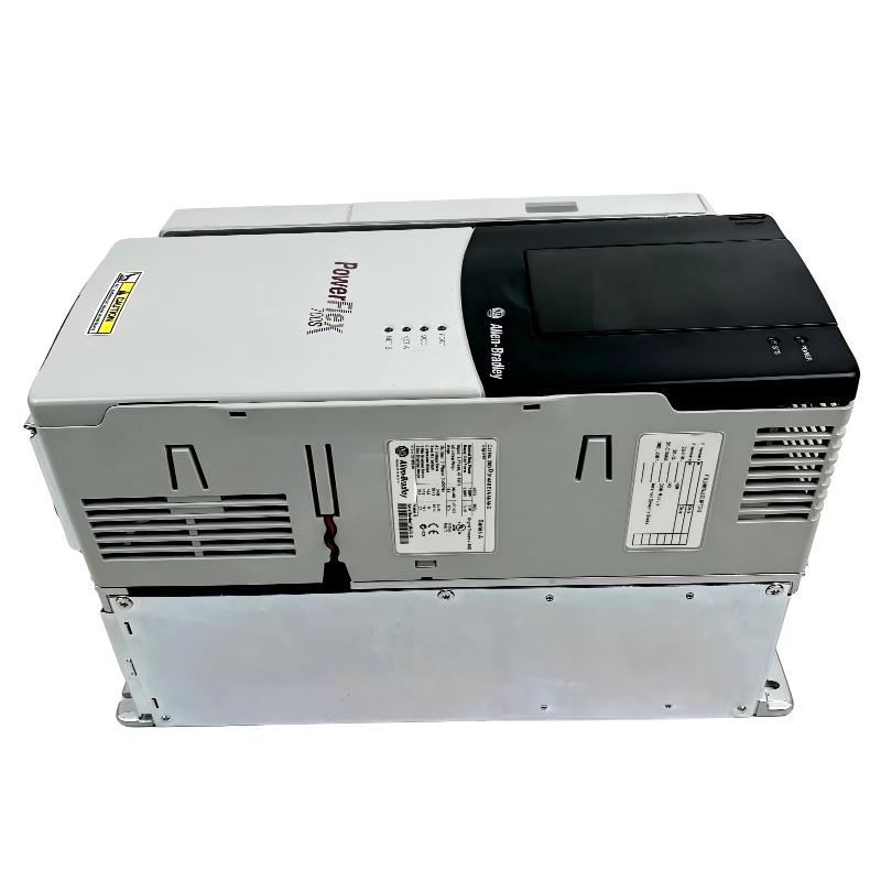
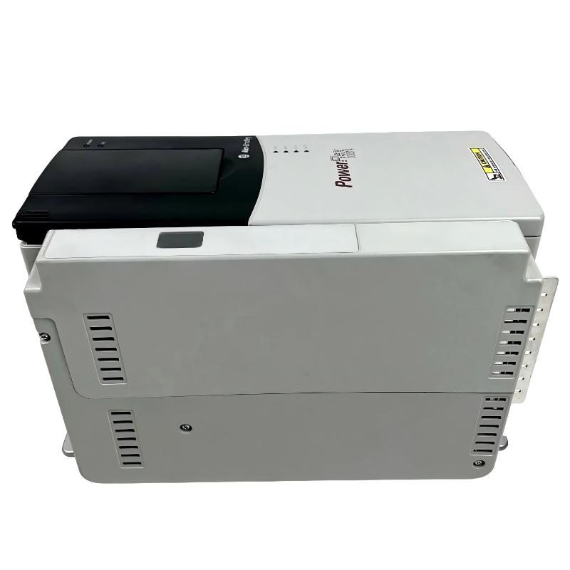
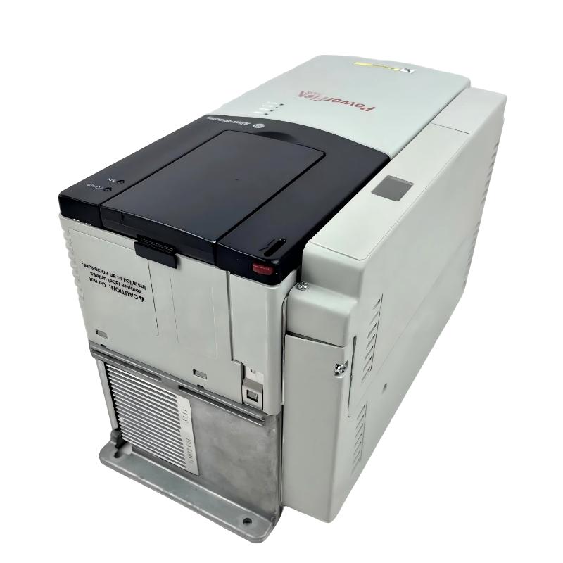
- Allen Bradley
- 20DR180A3NNNACANE
- PowerFlex AC Drive
- USA
- 540 mm x 330 mm x 210 mm
- 384 kg
- Xiamen, China
- New & In Stock
- T/T, PayPal, Western Union
- 1 Year
- 1-3 Working Days
- DHL, UPS, TNT, FedEx and EMS.
- 24-Hour Service
- COO
- 81
Our advantage

Global Logistics
We have a 10-year logistics and express cooperation agreement, so our products can be shipped to any place in the world.

Brand new and original
Our products are imported in bulk from the place of origin. Because of the cooperative relationship, our products are all original and 100% new.

24-hour service
We provide 7*24 hours service to our customers. We will be there whenever you need us.

Price advantage
All our products are priced very favorably because we have our own warehouse and supply.
| Company Information | |||
| [email protected] | |||
| Mobile | +8615980777398 | ||
| +8615980777398 | |||
| 15980777398 |
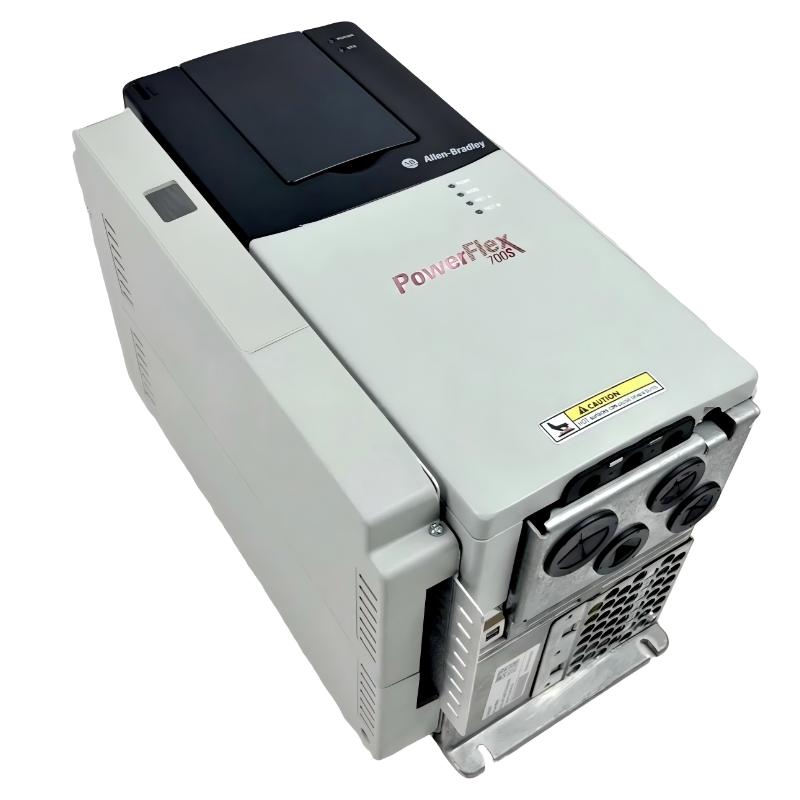
20DR180A3NNNACANE — Detailed Product Overview and Technical Guide
1. Product Introduction
The 20DR180A3NNNACANE is a high-power industrial AC drive belonging to the PowerFlex 700S, 20D series.
It is designed for demanding industrial motor-control applications where high output current, controlled acceleration and deceleration, accurate speed regulation, torque control, and integration with a larger automation system are required.
The drive has a 650 VDC pre-charge input, a 180 A continuous output rating, a 150 HP normal-duty rating, and a 125 HP heavy-duty rating. It is a Frame 6 unit with an IP20/NEMA Type 1 enclosure arrangement.
The model is substantially larger than a small or medium general-purpose variable-frequency drive. With approximate dimensions of 850.0 mm × 435.8 mm × 275.5 mm and a drive weight of approximately 71.44 kg, it is intended for serious industrial installations with adequate cabinet space, mechanical support, electrical protection, and cooling.
One of the most important characteristics of this particular configuration is its 650 VDC pre-charge architecture. This makes it different from a conventional AC-input VFD and particularly relevant to DC-bus and multi-drive industrial systems.
The complete catalog number is important when identifying or replacing the unit. The 20DR180A3NNNACANE configuration should not be assumed to be interchangeable with every other 20DR180 model because suffix variations can represent different hardware and option configurations.
2. Brand and Series
| Category | Specification |
|---|---|
| Brand | Allen-Bradley |
| Product family | PowerFlex |
| Product series | PowerFlex 700S |
| Catalog family | 20D |
| Product type | High-performance AC drive |
| Complete model | 20DR180A3NNNACANE |
| Input voltage class | 650 VDC |
| Input arrangement | DC pre-charge |
| Continuous output current | 180 A |
| Normal-duty rating | 150 HP |
| Heavy-duty rating | 125 HP |
| Mechanical frame | Frame 6 |
| Control architecture | Phase II |
| Communication | ControlNet coaxial |
| Enclosure | IP20 / NEMA / UL Type 1 |
| Cooling | Forced air |
| Application class | High-power industrial motor control |
The exact product configuration identifies the unit as a PowerFlex 700S 20D drive with 650 VDC pre-charge, 180 A output capability, 150 HP normal-duty capacity and 125 HP heavy-duty capacity.
3. Basic Product Identification
The complete catalog number is:
20DR180A3NNNACANE
The model can be broadly understood as a high-capacity 20D-series drive with a 650 VDC input class and an 180 A output rating.
The 20D portion identifies the product family.
The R configuration corresponds to the 650 VDC pre-charge arrangement.
The 180 represents the 180 A output-current class.
The remaining characters define the particular hardware and option configuration.
For industrial maintenance, purchasing, and replacement purposes, the complete catalog number should always be retained.
It is not advisable to order a replacement using only “180 A, 150 HP” because two units with similar electrical ratings may have different communications, feedback, filtering, braking, input, or control configurations.
4. Main Technical Parameters
| Parameter | Specification |
|---|---|
| Model | 20DR180A3NNNACANE |
| Product family | PowerFlex 700S |
| Catalog family | 20D |
| Input voltage | 650 VDC |
| Input configuration | Pre-charge |
| Input phases | 3-phase, six-pulse |
| Continuous output current | 180 A |
| 1-minute output current | 234 A |
| 3-second output current | 312 A |
| Normal-duty motor rating | 150 HP |
| Heavy-duty motor rating | 125 HP |
| Approx. normal-duty power | 110 kW class |
| Approx. heavy-duty power | 93 kW class |
| Normal-duty input current | 198 A |
| Maximum output voltage | 932 V |
| Output phases | 3 |
| Frame | 6 |
| PWM drive rating | 4 kHz at 650 VDC |
| Carrier-frequency settings | 2, 4, 6, 8, 10 kHz |
| Maximum output frequency | 400 Hz |
| Enclosure | IP20 / NEMA / UL Type 1 |
| Control architecture | Phase II |
| Communication | ControlNet coaxial |
| Digital inputs | 6 |
| Digital outputs | 2 |
| Analog inputs | 3 |
| Analog outputs | 2 |
| Display | LCD |
| Keypad | Full numeric keypad |
| EMC filtering | EMC filter + common-mode choke |
| Internal brake IGBT | No |
| Internal brake resistor | No |
| Motor overload protection | Class 10 |
| Efficiency | Approx. 97.5% |
| Power loss | Approx. 1908 W |
| Height | 850.0 mm |
| Width | 435.8 mm |
| Depth | 275.5 mm |
| Dimensions | Approx. 850.0 × 435.8 × 275.5 mm |
| Weight | Approx. 71.44 kg |
| Operating temperature without derating | 0–40 °C |
| Rated operating condition | Up to 50 °C under specified conditions |
| Maximum altitude without derating | 1000 m |
| Relative humidity | 5–95%, non-condensing |
The published specifications identify the 180 A continuous rating, 234 A one-minute rating, 312 A three-second rating, 650 VDC pre-charge input, 150 HP normal-duty rating, 125 HP heavy-duty rating, Frame 6 construction, and approximately 1908 W power loss.
5. Electrical Rating
The main electrical rating of the 20DR180A3NNNACANE is 180 A continuous output current.
The drive also provides short-duration overload capability.
| Operating Condition | Current Rating |
|---|---|
| Continuous output | 180 A |
| 1-minute output | 234 A |
| 3-second output | 312 A |
| Normal-duty rating | 150 HP |
| Heavy-duty rating | 125 HP |
The 234 A one-minute rating provides additional short-duration capacity, while the 312 A three-second rating is intended for brief high-current events such as acceleration or temporary load peaks.
These values should not be interpreted as continuous operating ratings.
The actual drive selection should always be based on the motor nameplate current, duty cycle, acceleration requirements, ambient conditions, and application load profile.
6. Normal Duty and Heavy Duty
The drive has two important motor-capacity classifications.
| Duty | Motor Rating | Approximate Metric Power |
|---|---|---|
| Normal Duty | 150 HP | 110 kW class |
| Heavy Duty | 125 HP | 93 kW class |
Normal-duty applications generally have less severe overload requirements.
Heavy-duty applications can involve higher starting torque, frequent acceleration, sudden load changes, or repeated overload conditions.
For this reason, a 150 HP motor should not automatically be assumed to be suitable simply because the horsepower appears to match the normal-duty rating.
The motor’s actual full-load current and the mechanical duty of the machine are more important.
7. 650 VDC Pre-Charge Input
The 650 VDC pre-charge input is a defining feature of this drive.
This is different from a conventional three-phase AC-input VFD.
The drive is intended for systems in which the power architecture supplies a high-voltage DC bus.
The pre-charge arrangement controls the initial charging of the drive’s DC-link capacitors.
This is particularly relevant when the drive is installed as part of a common DC-bus system.
The upstream DC-bus equipment must therefore be designed specifically for the voltage, current, protection, isolation, and pre-charge requirements of the installation.
8. DC Common-Bus Applications
The drive is well suited to industrial systems in which multiple drives share a DC power architecture.
Typical applications include:
- Large conveyor systems.
- Multi-motor production lines.
- Material-handling machinery.
- Winding and unwinding equipment.
- Paper-processing machinery.
- Large machine tools.
- Process machinery.
- Coordinated production equipment.
A common DC-bus system can be useful when several motors operate as part of the same machine.
The exact system architecture should be engineered around the complete drive group rather than considering each drive independently.
9. Phase II Control
The 20DR180A3NNNACANE includes Phase II control and an expanded cassette.
This is an important part of the drive’s high-performance positioning.
The control architecture provides more sophisticated motor-control functions than a simple frequency-only drive.
Depending on the motor and configuration, the drive supports field-oriented control with or without feedback and permanent-magnet motor control.
This makes the drive appropriate for applications where speed and torque behavior have a direct effect on machine performance.
10. Speed-Control Capability
The published specification identifies speed regulation of approximately 0.1% of base speed across a 120:1 speed range without feedback, with a stated operating bandwidth.
This is useful in applications where stable motor speed is important.
Typical examples include:
- Large conveyors.
- Roll drives.
- Process machinery.
- Material handling.
- Pumps.
- Fans.
- Production machinery.
The actual result in a machine depends on motor parameters, drive tuning, load characteristics, operating speed, and the selected control mode.
11. Torque-Control Capability
The published specification identifies torque regulation without feedback at approximately ±5%, with a stated bandwidth of 600 rad/sec.
Torque regulation is useful when the mechanical process depends on maintaining a predictable motor torque.
Typical applications include:
- Conveyor systems.
- Winding equipment.
- Roll drives.
- Material-processing equipment.
- High-inertia machines.
- Tension-control systems.
This capability becomes especially valuable when speed alone is not enough to control the machine.
12. Motor-Control Methods
The drive supports several motor-control approaches.
| Control Function | Availability |
|---|---|
| Field-oriented control without feedback | Yes |
| Field-oriented control with feedback | Supported by applicable configuration |
| Permanent-magnet motor control | Yes |
| Current-regulated control | Yes |
| Sine-coded PWM | Yes |
| Programmable carrier frequency | Yes |
| Induction motor control | Yes |
| Brushless motor control | Supported |
The combination of these functions makes the 20DR180 substantially more flexible than a simple V/Hz-only drive.
13. PWM and Carrier Frequency
The drive is rated for 4 kHz PWM at 650 VDC under normal-duty conditions.
The available carrier-frequency settings include:
| Carrier Frequency | Status |
|---|---|
| 2 kHz | Available |
| 4 kHz | Available |
| 6 kHz | Available for specified V/Hz operation |
| 8 kHz | Available |
| 10 kHz | Available |
The carrier frequency should be selected according to the application.
Increasing the switching frequency can reduce audible motor noise, but it can also increase switching losses and thermal loading.
For a large 180 A drive, thermal considerations are especially important.
14. Maximum Output Frequency
The maximum output frequency is specified as 400 Hz.
This is an electrical capability rather than a recommendation to operate every motor at 400 Hz.
The actual motor speed limit must be checked against the motor manufacturer’s mechanical specifications.
At high speed, bearing speed, rotor balance, cooling, mechanical resonance, and load characteristics can become important.
15. Input and Output Configuration
| Parameter | Specification |
|---|---|
| Input voltage | 650 VDC |
| Input arrangement | Pre-charge |
| Input phases | 3-phase |
| Input topology | Six-pulse |
| Output phases | 3-phase |
| Output voltage range | 0 to rated motor voltage |
| Maximum output voltage | 932 V |
| Maximum input frequency | 400 Hz |
| DC bus | High-voltage DC architecture |
| Continuous output current | 180 A |
The published specification identifies a three-phase six-pulse input arrangement and three-phase output.
16. Fuse and Protection
The specified fuse current rating is 400 A at 650 VDC for normal-duty operation.
This is an important point when designing or maintaining the upstream DC system.
The protection device should not simply be selected according to the motor’s horsepower.
The complete installation must account for:
- DC-bus voltage.
- Drive input current.
- Fuse characteristics.
- Short-circuit current.
- Cable rating.
- Disconnect requirements.
- Bus architecture.
- Local electrical standards.
The published maximum short-circuit current rating when using the recommended protective device is up to 200,000 A, subject to the specified protection arrangement.
17. EMC Filtering
This configuration includes an EMC filter and common-mode choke.
This is valuable in industrial environments where electromagnetic compatibility is important.
A high-power PWM drive can generate high-frequency electrical noise.
The EMC components help manage conducted interference, but they are only one part of the overall EMC design.
Good installation practice should also include:
- Correct grounding.
- Appropriate motor cable.
- Proper cable shielding where required.
- Separation of power and control wiring.
- Appropriate cabinet layout.
- Correct bonding.
18. Brake Configuration
The drive does not include an internal brake IGBT and does not include an internal drive-mounted brake resistor.
This is important for applications that require fast stopping.
For a high-inertia load, deceleration can return mechanical energy to the DC bus.
The system therefore needs an appropriate strategy.
Possible approaches include:
- Longer deceleration ramps.
- External braking equipment.
- Regenerative power handling.
- Mechanical braking.
The correct solution depends on the load inertia, speed, stopping time, number of stops, and process requirements.
19. Acceleration and Deceleration
Acceleration and deceleration times are independently programmable.
The specified adjustment range is from 0 to 6553.5 seconds, with 0.1-second increments.
This provides substantial flexibility for large machines.
A large conveyor, for example, can use a longer acceleration time to reduce mechanical shock.
A pump may use a relatively smooth acceleration profile.
A production machine may require a more carefully controlled speed transition.
20. S-Curve Acceleration
The drive supports adjustable S-curve time.
The specified range is approximately 0.5 to 4.0 seconds.
S-curve acceleration can be useful where a simple linear ramp produces too much mechanical shock.
The motor torque can be introduced and removed more progressively.
This can be beneficial for:
- Conveyors.
- Material handling.
- Rollers.
- Lifting machinery.
- Large rotating equipment.
21. Protection Functions
The drive provides a range of electrical and motor-protection functions.
| Protection / Function | Description |
|---|---|
| Motor overload | Class 10 electronic overload |
| Drive overcurrent | Software current-limit/trip |
| DC-bus undervoltage | Adjustable trip |
| Phase-to-phase fault | Output short-circuit detection |
| Ground fault | Phase-to-ground detection |
| Heat sink temperature | Microprocessor monitoring |
| Motor over-temperature | Supported protection function |
| Power ride-through | Approximately 15 ms at full load |
| Logic ride-through | Approximately 0.25 s under specified condition |
| Line transient immunity | Specified high-voltage transient tolerance |
| Control noise immunity | Specified transient protection |
The electronic motor overload protection is identified as Class 10 under the applicable requirements.
22. I/O Configuration
The 20DR180A3NNNACANE provides a useful collection of onboard control I/O.
| I/O Type | Quantity |
|---|---|
| Digital inputs | 6 |
| Digital outputs | 2 |
| Analog inputs | 3 |
| Analog outputs | 2 |
| Display | LCD |
| Keypad | Full numeric keypad |
| Communication | ControlNet coaxial |
This arrangement can reduce the need for external interface hardware in some machine-control applications.
23. ControlNet Communication
The exact configuration includes ControlNet coaxial communication.
This is particularly relevant to legacy industrial automation systems.
When the drive is part of an existing machine, the communication configuration can be just as important as the motor rating.
A replacement project may need to account for:
- PLC communication.
- Network configuration.
- Drive parameter mapping.
- HMI data.
- Fault reporting.
- Start/stop commands.
- Speed references.
- Status feedback.
Maintaining the same communication architecture can reduce the amount of modification required to an existing control system.
24. Dimensions and Weight
The physical size of this model is important for installation planning.
| Mechanical Parameter | Specification |
|---|---|
| Model | 20DR180A3NNNACANE |
| Frame | 6 |
| Height | 850.0 mm |
| Width | 435.8 mm |
| Depth | 275.5 mm |
| Overall dimensions | Approx. 850.0 × 435.8 × 275.5 mm |
| Weight | Approx. 71.44 kg |
| Enclosure | IP20 / NEMA / UL Type 1 |
| Cooling | Forced air |
| Installation | Industrial cabinet |
| Cabinet required | Yes |
| Service clearance | Required |
| Cable clearance | Required |
| Additional cabinet equipment | Not included in drive dimensions |
The exact listed physical dimensions are approximately 850.0 mm high, 435.8 mm wide and 275.5 mm deep, with a drive weight of approximately 71.44 kg.
The 71.44 kg figure refers to the drive itself.
It does not represent the total weight of the cabinet, disconnects, fuses, busbars, cables, cooling equipment, or other installed components.
25. Thermal Characteristics
The published power loss is approximately 1908 W at 650 VDC and 150 HP normal duty.
This is a substantial heat load.
The cabinet designer should therefore calculate the total thermal load rather than relying on natural cooling assumptions.
| Thermal Parameter | Value / Requirement |
|---|---|
| Drive power loss | Approx. 1908 W |
| Cooling | Forced air |
| Ambient without derating | 0–40 °C |
| Specified rated condition | Up to 50 °C |
| Heat generated | Significant |
| Cabinet ventilation | Required |
| Fan condition | Must be maintained |
| Airflow path | Must remain unobstructed |
A dirty cooling path can raise the internal temperature of the drive.
For an older industrial machine, cleaning and checking the cooling system should therefore be part of routine maintenance.
26. Environmental Specifications
| Environmental Parameter | Specification |
|---|---|
| Operating temperature without derating | 0–40 °C |
| Rated operating temperature | 50 °C under specified 650 VDC normal-duty condition |
| Storage temperature | Down to approximately -40 °C |
| Relative humidity | 5–95%, non-condensing |
| Maximum altitude without derating | 1000 m |
| Enclosure | IP20 / NEMA / UL Type 1 |
| Shock | 10 G peak for 11 ms |
| Vibration | 1 G peak, specified conditions |
| Installation atmosphere | Free of corrosive/volatile contamination |
The drive should not be installed where corrosive or volatile gases, vapors, or conductive dust can attack the electronics.
27. Typical Applications
| Application | Suitability | Main Reason |
|---|---|---|
| Large conveyor | Excellent | High current and controlled acceleration |
| Mining conveyor | Excellent | Large motor capacity |
| Bulk material handling | Excellent | High torque and speed control |
| Large pump | Excellent | Variable-speed process control |
| Large fan | Excellent | Adjustable speed |
| Industrial blower | Excellent | High-power motor control |
| Mixer | Very good | High torque requirements |
| Process machinery | Excellent | Advanced control |
| Roller drive | Very good | Speed and torque regulation |
| Winding equipment | Very good | Controlled speed/torque |
| Compressor | Good | Requires application-specific review |
| High-inertia machine | Good | Braking analysis required |
| Hoist | Requires engineering | Load and braking considerations |
| Small motor | Poor | Drive is oversized |
28. Conveyor Applications
Large conveyors are one of the strongest applications for a drive of this class.
A conveyor can have considerable mechanical inertia, especially when it is carrying material.
A sudden application of motor torque can create mechanical stress.
Controlled acceleration can help reduce stress on:
- Gearboxes.
- Couplings.
- Shafts.
- Bearings.
- Belts.
- Chains.
- Structural components.
The short-duration current capacity can also help with temporary load increases during acceleration.
29. Mining and Bulk Material Handling
Mining and bulk-material applications often involve demanding mechanical conditions.
Examples include:
- Ore conveyors.
- Aggregate conveyors.
- Feed systems.
- Transfer conveyors.
- Crushers and associated machinery.
- Material-processing systems.
The 180 A output class provides substantial motor capacity.
However, heavy-duty sizing should be based on actual motor current and torque requirements.
30. Pump Applications
Large industrial pumps can benefit from variable-speed operation.
The drive can adjust motor speed according to the process.
Possible control variables include:
- Pressure.
- Flow.
- Tank level.
- Cooling demand.
- Process load.
Variable-speed operation can provide smoother starting and improved process control.
Potential energy savings depend on the pump and piping system and should be calculated from the actual operating profile.
31. Fan and Blower Applications
Large fans and blowers are another good application.
Typical uses include:
- Industrial ventilation.
- Exhaust systems.
- Dust extraction.
- Process air.
- Cooling systems.
- Combustion-air systems.
Variable-speed operation allows the machine to match airflow to process demand.
32. Process Machinery
The high-performance control functions are useful in machines where speed and torque are directly related to the production process.
Possible applications include:
- Rollers.
- Mixers.
- Agitators.
- Material processors.
- Winding systems.
- Large production machines.
- Process lines.
- Industrial rotating equipment.
The actual control performance depends on motor characteristics, parameter setup, tuning, and machine mechanics.
33. High-Inertia Applications
High-inertia applications require careful analysis.
During acceleration, the drive must supply additional torque.
During deceleration, the rotating load can return energy to the DC bus.
This is particularly important because this specific configuration has no internal brake IGBT or internal brake resistor.
Important engineering parameters include:
| Parameter | Importance |
|---|---|
| Motor inertia | Critical |
| Load inertia | Critical |
| Maximum speed | Critical |
| Acceleration time | Important |
| Deceleration time | Critical |
| Number of stops | Critical |
| Regenerative energy | Critical |
| Braking method | Critical |
| Mechanical brake | Application-dependent |
34. Main Product Advantages
34.1 High Output Current
The 180 A continuous rating makes the drive suitable for large industrial motors.
It provides a significant amount of electrical capacity without immediately moving to a larger 248 A or 300 A configuration.
34.2 Large Motor Capacity
The 150 HP normal-duty rating places the drive in the large industrial motor category.
This makes it appropriate for substantial production equipment.
34.3 Heavy-Duty Capability
The 125 HP heavy-duty rating provides additional flexibility for applications where overload performance is more important than simply matching horsepower.
34.4 Short-Term Overload Capability
The drive can provide:
- 234 A for one minute.
- 312 A for three seconds.
This can be useful for short acceleration events and temporary mechanical load increases.
34.5 High-Performance Control
The Phase II architecture supports sophisticated motor-control functions.
This makes the drive appropriate for machines where speed and torque response are important.
34.6 DC-Bus Architecture
The 650 VDC pre-charge design makes the drive suitable for DC-bus applications.
This can be useful in multi-drive industrial machines.
34.7 ControlNet Integration
For an existing machine using ControlNet, the integrated communication arrangement can be a major practical advantage.
It can help preserve an established control architecture.
34.8 EMC Filtering
The EMC filter and common-mode choke are useful for industrial installations where electrical noise management is important.
34.9 Extensive Programming Capability
The drive provides programmable acceleration, deceleration, S-curve control, current limits, motor-control modes, stop modes, and protection functions.
This allows the drive to be adapted to different machine operating requirements.
35. Five Same-Series or Closely Related Models
The following models are useful for comparison within the same general 650 VDC PowerFlex 700S family.
| Model | Continuous Current | Normal Duty | Heavy Duty | Frame | Approx. Power Class | Dimensions | Weight (kg) |
|---|---|---|---|---|---|---|---|
| 20DR125A3EYNACANE | 125 A | 100 HP | 75 HP | 5 | 75 kW class | Frame-dependent | Configuration-dependent |
| 20DR156A3NNNACANE | 156 A class | 125 HP | 100 HP | 6 | 90 kW class | Frame-dependent | Configuration-dependent |
| 20DR180A3NNNACANE | 180 A | 150 HP | 125 HP | 6 | 110 kW class | 850 × 435.8 × 275.5 mm | 71.44 |
| 20DR248A0NNNACGNE | 248 A | 200 HP | 150 HP | 6 | 132 kW class | Configuration-dependent | Configuration-dependent |
| 20DR300A3NNNACANE | 300 A class | 250 HP | 200 HP | 9 | 160 kW class | Frame-dependent | Configuration-dependent |
The exact 20DR180 configuration and related 20DR models are documented as members of the same PowerFlex 700S 20D product family.
Because suffix options differ between catalog numbers, the table should be treated as a capacity comparison rather than a statement that every suffix has identical hardware.
36. Five Recommended Same-Series Models
| Model | Current Class | Normal Duty | Heavy Duty | Frame | Best Use | Dimensions | Weight (kg) |
|---|---|---|---|---|---|---|---|
| 20DR125 | 125 A | 100 HP | 75 HP | 5 | Medium-large motor systems | Frame-dependent | Configuration-dependent |
| 20DR156 | 156 A | 125 HP | 100 HP | 6 | Large pumps and conveyors | Frame-dependent | Configuration-dependent |
| 20DR180 | 180 A | 150 HP | 125 HP | 6 | Large industrial machinery | 850 × 435.8 × 275.5 mm class | 71.44 |
| 20DR248 | 248 A | 200 HP | 150 HP | 6 | Larger industrial motors | Frame-dependent | Configuration-dependent |
| 20DR300 | 300 A | 250 HP | 200 HP | 9 | Heavy industrial equipment | Frame-dependent | Configuration-dependent |
37. Same-Series Selection Comparison
| Model | Continuous Current | Normal-Duty Rating | Heavy-Duty Rating | Relative Size | Recommended Situation |
|---|---|---|---|---|---|
| 20DR125 | 125 A | 100 HP | 75 HP | Smaller | Lower motor-current requirements |
| 20DR156 | 156 A | 125 HP | 100 HP | Medium | Medium-large machinery |
| 20DR180 | 180 A | 150 HP | 125 HP | Large | 150 HP-class industrial machinery |
| 20DR248 | 248 A | 200 HP | 150 HP | Larger | 200 HP-class machinery |
| 20DR300 | 300 A | 250 HP | 200 HP | Very large | Heavy industrial applications |
The 20DR180 sits in a useful position between the 156 A and 248 A classes.
For a 150 HP normal-duty motor, it is a natural capacity match when the electrical and mechanical requirements are otherwise appropriate.
38. Five Related Models from the Same Brand
For broader comparison, the following models represent other products from the same brand and related industrial-drive portfolio.
| Model | Product Family | Capacity Class | Typical Application | Control Level | Dimensions | Weight (kg) |
|---|---|---|---|---|---|---|
| 20DR125A3EYNACANE | PowerFlex 700S / 20D | 125 A / 100 HP class | Pumps, conveyors | High performance | Frame-dependent | Configuration-dependent |
| 20DR180A3NNNACANE | PowerFlex 700S / 20D | 180 A / 150 HP class | Large industrial machinery | High performance | 850 × 435.8 × 275.5 mm | 71.44 |
| 20DR248A0NNNACGNE | PowerFlex 700S / 20D | 248 A / 200 HP class | Large conveyors/process equipment | High performance | Configuration-dependent | Configuration-dependent |
| 20F11FD065AA0NNNNN | PowerFlex 753 | 65 A class | Pumps, fans, conveyors | Advanced general-purpose | Frame-dependent | Configuration-dependent |
| 20G11RD011AA0NNNNN | PowerFlex 755 | 11 A class | Machine/process control | Advanced | Frame-dependent | Configuration-dependent |
These should be considered comparison products, not automatic replacements.
The 20D family has a different architecture from the later 753/755 product families.
39. Five Broader Popular Model Choices
When considering widely encountered products from the same brand, the following are useful reference points.
| Model | Product Family | General Capacity | Typical Application | Main Advantage | Dimensions | Weight (kg) |
|---|---|---|---|---|---|---|
| 20F11FD065AA0NNNNN | PowerFlex 753 | 65 A class | Pumps, fans, conveyors | General industrial flexibility | Frame-dependent | Configuration-dependent |
| 20G11RD011AA0NNNNN | PowerFlex 755 | 11 A class | Machine control | Advanced control | Frame-dependent | Configuration-dependent |
| 20G173F215LNDNNNNN | PowerFlex 755 | High-power class | Large industrial machinery | High-performance control | Frame-dependent | Configuration-dependent |
| 20BB260A0ANNANC0 | PowerFlex 700 | High-current class | Large motor applications | High-power drive architecture | Frame-dependent | Configuration-dependent |
| 20BB104A0AYNANC0 | PowerFlex 700 | Medium-high current | Industrial machinery | Established industrial platform | Frame-dependent | Configuration-dependent |
The word “popular” here should be understood as commonly encountered industrial product families and representative catalog configurations, rather than a formal sales ranking.
40. Application Suitability Table
| Application | Suitability | Main Consideration |
|---|---|---|
| Large conveyor | Excellent | High current and controlled acceleration |
| Mining conveyor | Excellent | High torque and heavy load |
| Bulk material handling | Excellent | Large motor capacity |
| Large pump | Excellent | Variable-speed process control |
| Large fan | Excellent | Adjustable speed |
| Industrial blower | Excellent | Large motor control |
| Mixer | Very good | Torque requirement |
| Process machine | Excellent | Advanced control |
| Roller | Very good | Speed/torque control |
| Winder | Very good | Tension and torque control |
| Compressor | Good | Compressor-specific engineering |
| Centrifuge | Good | High-inertia/braking analysis |
| Hoist | Requires engineering | Braking and safety requirements |
| Small motor | Poor | Excessive drive capacity |
41. Cabinet Design
The physical dimensions of the drive are significant.
At approximately 850.0 mm × 435.8 mm × 275.5 mm, the drive occupies substantial vertical cabinet space.
The cabinet must provide additional space for:
- DC-bus connections.
- Motor cables.
- Grounding.
- Protective devices.
- Control wiring.
- Communication cables.
- Cooling airflow.
- Service access.
The cabinet should not be designed around the drive’s external dimensions alone.
Cable bending radius and maintenance access can require considerably more space.
42. Thermal Management
The approximately 1908 W heat loss is one of the most important installation considerations.
A practical cabinet calculation should include:
Drive heat + other drives + power supplies + contactors + control equipment + auxiliary components = total cabinet heat load.
The result determines the cooling strategy.
Possible solutions include:
- Filtered forced-air ventilation.
- Heat exchangers.
- Cabinet air conditioning.
- Larger enclosure volume.
- External cooling arrangements.
The selected solution depends on the ambient temperature and enclosure design.
43. Motor Selection
The drive should be matched to the motor using electrical current rather than horsepower alone.
| Motor Parameter | Importance |
|---|---|
| Motor voltage | Critical |
| Full-load current | Critical |
| Motor horsepower | Important |
| Rated frequency | Important |
| Rated speed | Important |
| Service factor | Important |
| Starting torque | Critical |
| Breakdown torque | Important |
| Motor insulation | Important |
| Cooling method | Important |
| Encoder/feedback | Application-dependent |
| Maximum operating speed | Critical |
The 180 A drive rating does not automatically mean that any 150 HP motor can be connected without further analysis.
44. Maintenance Recommendations
A preventive-maintenance program should include:
- Inspect cooling fans.
- Check cabinet ventilation.
- Inspect power connections.
- Check DC-bus connections.
- Inspect motor terminals.
- Check grounding.
- Review drive fault history.
- Inspect communication connections.
- Check the LCD/keypad.
- Inspect for overheating.
- Check cabinet contamination.
- Maintain parameter backups.
- Record the complete catalog number.
- Record all installed options.
- Keep replacement information available.
For an older industrial machine, keeping a complete parameter backup can significantly reduce downtime after a drive failure.
45. Replacement Considerations
A replacement should not be selected solely by horsepower.
| Replacement Parameter | Importance |
|---|---|
| Complete catalog number | Critical |
| 650 VDC input | Critical |
| Pre-charge arrangement | Critical |
| 180 A continuous current | Critical |
| 150 HP normal duty | Critical |
| 125 HP heavy duty | Critical |
| Frame 6 | Important |
| Phase II control | Critical |
| ControlNet | Critical if used |
| Feedback | Critical if used |
| EMC filtering | Important |
| Brake configuration | Critical |
| Cabinet dimensions | Critical |
| Weight | Important |
| Cooling | Critical |
| Motor parameters | Critical |
A drive with the same horsepower rating but a different DC-bus arrangement may not be a suitable replacement.
46. Lifecycle Status
The exact product listing identifies the 20DR180A3NNNACANE as discontinued, with a discontinuation date of June 30, 2023, and an engineering-replacement category.
This is an important consideration for procurement.
The model can still be encountered in installed industrial equipment and replacement inventories.
For an existing machine, retaining the same architecture can sometimes be the most practical way to minimize machine modifications and downtime.
For a new machine, however, the discontinued status should be considered during the engineering stage.
A newer drive platform may provide better long-term availability and modern communication capabilities, but migration can involve changes to PLC programming, parameters, wiring, communication, HMI configuration, and commissioning.
47. Main Advantages and Limitations
| Category | Assessment |
|---|---|
| Continuous output | Excellent |
| 150 HP normal duty | Excellent |
| 125 HP heavy duty | Very good |
| Short-term overload | Excellent |
| Speed control | Very good |
| Torque control | Very good |
| Phase II control | Excellent |
| DC-bus architecture | Excellent for appropriate systems |
| ControlNet integration | Very useful for compatible legacy systems |
| EMC filtering | Good |
| Cabinet size | Large |
| Weight | High |
| Cooling requirement | Significant |
| Internal braking | Not included |
| Industrial robustness | Very good |
| New-project lifecycle | Requires careful consideration |
| Existing-machine replacement | Potentially very useful |
48. Practical Advantages for Existing Industrial Equipment
The strongest practical advantage of the 20DR180A3NNNACANE can be its compatibility with an existing machine architecture.
A drive is rarely an isolated component.
It can be connected to:
- PLC systems.
- HMIs.
- ControlNet networks.
- Motor feedback systems.
- External braking systems.
- Process instrumentation.
- Safety circuits.
- Machine interlocks.
- Production databases.
Replacing the drive with a completely different architecture can therefore create substantial engineering work.
Maintaining the same drive family can sometimes reduce the scope of modifications.
49. Practical Limitations
The model also has several limitations that should be understood clearly.
First, it is a large physical unit.
The approximately 71.44 kg drive requires appropriate mechanical support.
Second, it generates approximately 1908 W of heat under the specified normal-duty rating condition.
Third, it has no internal brake IGBT or internal brake resistor.
Fourth, it is a discontinued product.
Fifth, the 650 VDC architecture means that the installation is considerably different from a standard low-voltage AC-input VFD.
None of these points automatically make the drive unsuitable.
They simply mean that the drive should be evaluated as part of the complete industrial machine.
50. Quick Technical Reference
| Parameter | Final Value |
|---|---|
| Model | 20DR180A3NNNACANE |
| Brand | Allen-Bradley |
| Product family | PowerFlex |
| Series | PowerFlex 700S |
| Catalog family | 20D |
| Input | 650 VDC |
| Input type | Pre-charge |
| Continuous output | 180 A |
| 1-minute output | 234 A |
| 3-second output | 312 A |
| Normal duty | 150 HP |
| Heavy duty | 125 HP |
| Approx. normal-duty power | 110 kW |
| Approx. heavy-duty power | 93 kW |
| Frame | 6 |
| Control | Phase II |
| Communication | ControlNet coaxial |
| EMC | Filter + common-mode choke |
| Brake IGBT | None |
| Internal brake resistor | None |
| PWM rating | 4 kHz at 650 VDC |
| Maximum output frequency | 400 Hz |
| Digital inputs | 6 |
| Digital outputs | 2 |
| Analog inputs | 3 |
| Analog outputs | 2 |
| Efficiency | Approx. 97.5% |
| Power loss | Approx. 1908 W |
| Height | 850.0 mm |
| Width | 435.8 mm |
| Depth | 275.5 mm |
| Dimensions | Approx. 850.0 × 435.8 × 275.5 mm |
| Weight | Approx. 71.44 kg |
| Enclosure | IP20 / NEMA / UL Type 1 |
| Operating temperature | 0–40 °C without derating |
| Maximum altitude without derating | 1000 m |
| Lifecycle | Discontinued |
51. Final Product Assessment
The 20DR180A3NNNACANE is a high-capacity industrial AC drive intended for large and technically demanding motor applications.
Its key electrical rating is 180 A continuous output, with 234 A available for one minute and 312 A for three seconds. The normal-duty motor rating is 150 HP, while the heavy-duty rating is 125 HP.
The combination of 650 VDC pre-charge input, Phase II control, advanced motor-control functions, ControlNet communication, EMC filtering, programmable acceleration/deceleration, and substantial overload capability makes it a serious industrial drive rather than a basic variable-frequency controller.
The model is particularly suitable for large conveyors, pumps, fans, blowers, process machinery, material-handling equipment, rollers, winders, and other large rotating machinery.
The physical specification is also important.
The approximate dimensions are 850.0 mm × 435.8 mm × 275.5 mm, and the drive weighs approximately 71.44 kg.
This means that cabinet design, mechanical mounting, ventilation, cable routing, and service access all need to be considered during installation.
The approximately 1908 W power loss is another significant engineering parameter.
A properly designed cooling system is necessary to keep the drive within its permitted operating temperature.
For applications involving high-inertia loads, the lack of an internal brake IGBT and internal brake resistor should be considered before commissioning the machine.
The braking method should be selected according to the load inertia, operating speed, stopping time, and number of braking events.
For replacement work, the complete 20DR180A3NNNACANE catalog number should be matched whenever possible.
The voltage class, pre-charge configuration, communication method, control architecture, feedback, EMC hardware, braking arrangement, dimensions, and motor duty all need to be checked before installing an alternative model.
The model is also a legacy/discontinued product, so long-term availability should be considered when planning new equipment.
For an existing production machine, however, the model can remain highly relevant because maintaining the established control architecture may be more practical than changing the complete drive system.
Overall, the 20DR180A3NNNACANE can be summarized as a 650 VDC, 180 A, 150 HP normal-duty, high-performance industrial AC drive in the PowerFlex 700S 20D family, with Phase II control and ControlNet communication.
Its strongest characteristics are its high current capacity, advanced motor control, common-DC-bus compatibility, overload capability, industrial I/O, and ability to handle large motor-driven machinery.
For a new installation, lifecycle considerations should be evaluated carefully.
For an existing installation, the exact catalog number, installed options, drive parameters, motor data, network configuration, and mechanical dimensions should all be documented before replacement or repair.