

ProductPRODUCT
Featured products








Contact Us
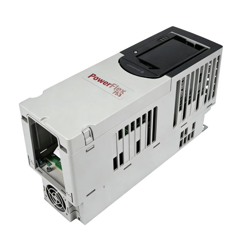
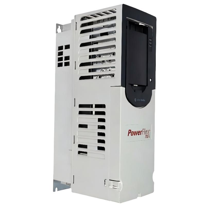
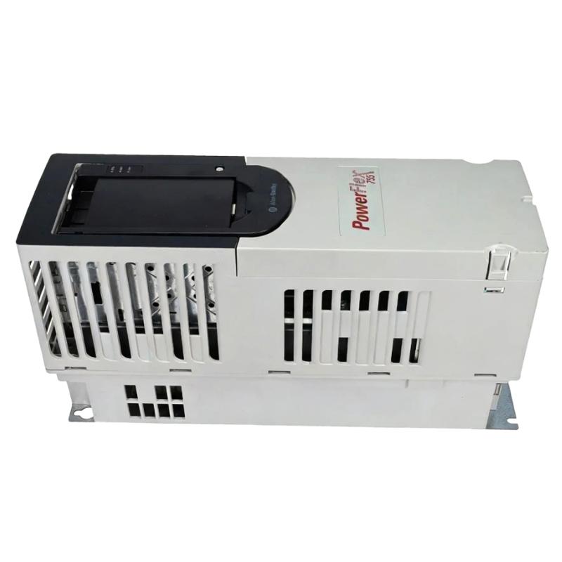
- Allen Bradley
- 20F1ANC205AA0NNNNN
- PowerFlex AC Drive
- USA
- 450–600 × 750–950 × 350–550 mm
- 80kg
- Xiamen, China
- New & In Stock
- T/T, PayPal, Western Union
- 1 Year
- 1-3 Working Days
- DHL, UPS, TNT, FedEx and EMS.
- 24-Hour Service
- COO
- 86
Our advantage

Global Logistics
We have a 10-year logistics and express cooperation agreement, so our products can be shipped to any place in the world.

Brand new and original
Our products are imported in bulk from the place of origin. Because of the cooperative relationship, our products are all original and 100% new.

24-hour service
We provide 7*24 hours service to our customers. We will be there whenever you need us.

Price advantage
All our products are priced very favorably because we have our own warehouse and supply.
| Company Information | |||
| [email protected] | |||
| Mobile | +8615980777398 | ||
| +8615980777398 | |||
| 15980777398 |
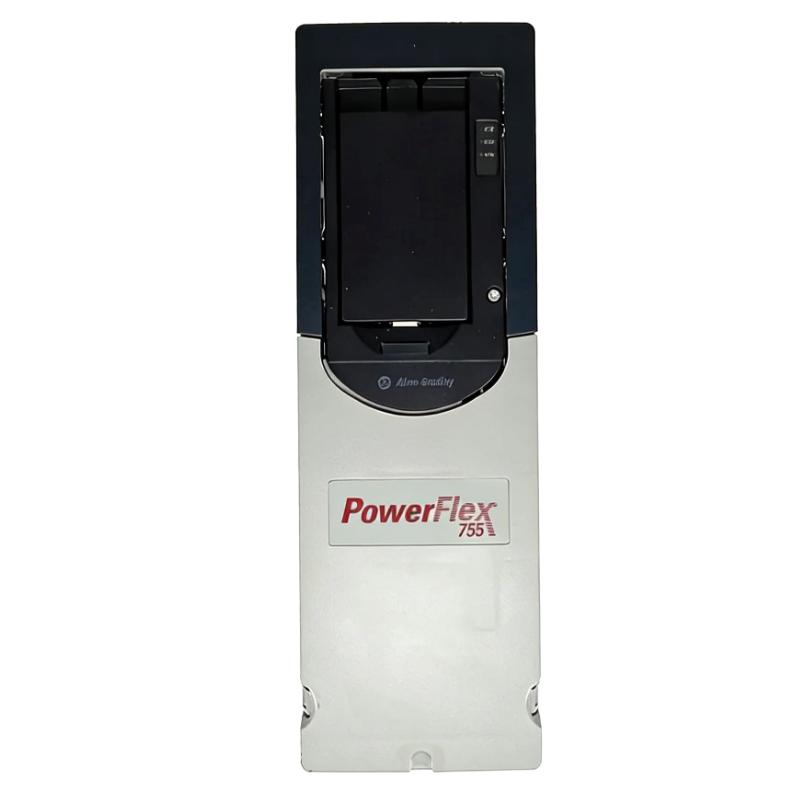
20F1ANC205AA0NNNNN — Product Overview, Technical Parameters, Applications, Advantages and Related Models
1. Product Overview
The 20F1ANC205AA0NNNNN is a high-capacity industrial adjustable-frequency AC drive intended for variable-speed control of three-phase AC motors.
It belongs to the PowerFlex 753 product series and is designed for industrial machinery where motor speed, acceleration, deceleration, protection and operating status need to be controlled more precisely than with a conventional motor starter.
With a current class of approximately 205 A and a 480 V-class configuration, this type of drive is intended for relatively large motors and demanding industrial loads.
Typical applications include heavy-duty conveyors, large pumps, fans, blowers, mixers, feeders, rollers, material-handling machinery and process equipment.
The drive acts as the electrical interface between the incoming three-phase power supply and the motor. It converts the incoming electrical power into a controlled variable-frequency output, allowing the motor to operate at different speeds according to the requirements of the machine.
2. Brand and Product Series
| Item | Description |
|---|---|
| Model | 20F1ANC205AA0NNNNN |
| Brand | Allen-Bradley |
| Product Family | PowerFlex |
| Product Series | PowerFlex 753 |
| Product Type | Adjustable-Frequency AC Drive |
| Voltage Class | 480 V class |
| Current Class | Approximately 205 A |
| Input | Three-phase AC |
| Output | Three-phase variable-frequency AC |
| Motor Type | Three-phase AC motor |
| Installation | Industrial panel / cabinet |
| Cooling | Forced-air cooling |
| Main Function | Variable-speed motor control |
| Typical Duty | Industrial continuous or variable-duty applications |
3. Product Introduction
The 20F1ANC205AA0NNNNN is intended for industrial motor-control applications in which the motor needs to operate at controlled speeds rather than simply being switched on and off.
A conventional motor starter generally provides basic starting and stopping.
An adjustable-frequency drive provides a much wider range of control.
The drive can regulate motor speed by controlling the frequency and voltage supplied to the motor.
This makes it possible to match motor operation to the actual requirements of the machine.
For example, a conveyor can operate at a low speed during loading and inspection and increase its speed during normal production.
A pump can adjust its speed according to flow or pressure demand.
A fan can reduce its speed when the required airflow decreases.
A mixer can operate at several different speeds during loading, mixing and discharge.
A feeder can change its speed according to the required material flow.
The drive can therefore become an important part of the complete machine-control system.
4. Basic Operating Principle
The basic power path can be represented as follows:
Three-Phase AC Power Supply
↓
Adjustable-Frequency Drive
↓
Controlled Voltage and Frequency
↓
Three-Phase AC Motor
↓
Mechanical Load
The drive receives electrical power from the industrial supply and produces a controlled output for the motor.
The output frequency is used to regulate motor speed.
The drive also manages motor-control characteristics according to the selected control method and configured motor parameters.
A control system can provide commands such as:
- Start.
- Stop.
- Speed reference.
- Direction.
- Preset speed.
- Process command.
The drive can provide operating information such as:
- Running status.
- Output frequency.
- Motor current.
- Speed information.
- Alarm status.
- Fault status.
- Drive condition.
This makes it suitable for integration into automated industrial machinery.
5. Main Technical Parameters
| Parameter | Reference Specification |
|---|---|
| Model | 20F1ANC205AA0NNNNN |
| Brand | Allen-Bradley |
| Product Family | PowerFlex |
| Product Series | PowerFlex 753 |
| Product Type | Adjustable-Frequency AC Drive |
| Voltage Class | 480 V class |
| Current Class | Approximately 205 A |
| Input Phase | Three-phase |
| Input Frequency | 50/60 Hz |
| Output Phase | Three-phase |
| Output Type | Variable-frequency AC |
| Motor Type | Three-phase AC motor |
| Variable-Speed Operation | Yes |
| Acceleration Control | Yes |
| Deceleration Control | Yes |
| Motor Protection | Integrated |
| Overcurrent Monitoring | Supported |
| Overvoltage Monitoring | Supported |
| Undervoltage Monitoring | Supported |
| Thermal Monitoring | Supported |
| Stall Protection | Supported |
| Fault Monitoring | Integrated |
| Diagnostic Functions | Integrated |
| PID Functions | Supported depending on configuration |
| Feedback | Configuration dependent |
| Communication | Configuration dependent |
| Cooling | Forced air |
| Mounting | Panel / cabinet |
| Approximate Width | 450–600 mm |
| Approximate Height | 750–950 mm |
| Approximate Depth | 350–550 mm |
| Approximate Overall Envelope | 450–600 × 750–950 × 350–550 mm |
| Approximate Weight | 55–80 kg |
| Weight Unit | kg |
The dimensions and weight above are intended for preliminary engineering planning.
The exact physical size and mass can vary according to the specific hardware configuration, mounting arrangement, accessories, enclosure arrangement and associated components.
For a final cabinet layout, lifting calculation or direct replacement, the exact mechanical data of the actual unit should be confirmed.
6. Catalog Number and Configuration
The complete catalog number 20F1ANC205AA0NNNNN identifies a specific configuration within the PowerFlex 753 family.
The complete catalog number is important when selecting a replacement because drives with similar current ratings can have different electrical or mechanical configurations.
The complete model number should therefore be retained during:
- Purchasing.
- Engineering.
- Maintenance.
- Spare-parts management.
- Replacement planning.
- Machine modernization.
| Identification | Description |
|---|---|
| Catalog Number | 20F1ANC205AA0NNNNN |
| Product Family | PowerFlex |
| Product Series | PowerFlex 753 |
| Product Type | Industrial AC Drive |
| Voltage Class | 480 V class |
| Current Class | Approximately 205 A |
| Input | Three-phase AC |
| Output | Variable-frequency three-phase AC |
| Installation | Industrial cabinet / panel |
| Cooling | Forced air |
| Intended Application | Large industrial motor control |
7. Variable-Speed Motor Control
One of the primary functions of the drive is variable-speed motor operation.
A fixed-speed motor generally operates at a speed determined primarily by its supply frequency and motor characteristics.
With an adjustable-frequency drive, the operating speed can be changed by changing the output frequency.
This allows a machine to operate at different speeds according to its process requirements.
A typical industrial sequence may be:
| Machine Condition | Typical Speed |
|---|---|
| Loading | Low speed |
| Initial operation | Low / medium speed |
| Normal production | Medium speed |
| High production demand | Higher speed |
| Inspection | Reduced speed |
| Product changeover | Low speed |
| Stopping | Controlled deceleration |
This approach can improve production flexibility and make it easier to coordinate several machine sections.
8. Controlled Acceleration
Large motors and heavy mechanical systems can contain substantial inertia.
Examples include:
- Heavy conveyor belts.
- Large rollers.
- Large fans.
- Blowers.
- Mixers.
- Material-handling systems.
Starting a high-inertia load abruptly can create significant mechanical stress.
The drive can use an acceleration ramp to increase motor speed progressively.
This can help reduce sudden loading on:
- Gearboxes.
- Couplings.
- Shafts.
- Bearings.
- Belts.
- Chains.
- Rollers.
Controlled acceleration can also make the machine easier to operate and reduce abrupt movement of transported material.
9. Controlled Deceleration
Controlled stopping is another important function.
Instead of immediately removing the motor’s operating command, the drive can reduce output frequency according to a configured deceleration profile.
This is useful for equipment with substantial inertia.
Typical examples include:
- Large conveyors.
- Rollers.
- Fans.
- Blowers.
- Mixers.
- Material-handling systems.
- Rotating processing equipment.
The correct stopping method depends on the load inertia, required stopping time and braking arrangement.
If very rapid stopping is required, the braking requirements should be evaluated separately.
10. Motor Speed Regulation
Motor speed can be used as a process-control parameter.
For example:
Low Speed → Loading
Medium Speed → Processing
High Speed → Production
Low Speed → Inspection
Controlled Stop → Unloading
The drive provides the electrical speed-control capability required for this type of operation.
This is especially useful when the motor is mechanically connected to:
- Conveyors.
- Pumps.
- Fans.
- Mixers.
- Feeders.
- Rollers.
- Production machinery.
11. Motor Protection
The drive incorporates monitoring and protection functions intended to help manage abnormal operating conditions.
Typical protection functions include:
- Overcurrent monitoring.
- Overvoltage monitoring.
- Undervoltage monitoring.
- Motor overload protection.
- Thermal monitoring.
- Stall-related protection.
- Drive temperature monitoring.
- Fault detection.
- Alarm detection.
- Feedback monitoring where applicable.
These functions can help prevent unsuitable operating conditions from developing into more serious equipment problems.
Correct configuration remains important.
Motor data, overload requirements and application duty should be entered and configured according to the actual motor and machine.
12. Diagnostic Capability
Diagnostic information is particularly valuable in industrial environments where unexpected downtime can affect production.
The drive can provide operating information such as:
| Information | Purpose |
|---|---|
| Drive Status | Indicates the current operating state |
| Motor Current | Shows electrical loading |
| Output Frequency | Indicates drive output |
| Speed Reference | Shows requested speed |
| Actual Speed | Indicates motor operation |
| Fault Status | Identifies shutdown conditions |
| Alarm Status | Identifies warning conditions |
| Temperature | Supports thermal diagnosis |
| Communication Status | Helps diagnose control-system problems |
| Operating Parameters | Supports commissioning and maintenance |
This information can help maintenance personnel distinguish between electrical, mechanical, thermal and control-related problems.
13. Automation Integration
The drive can be incorporated into an industrial automation architecture.
A typical arrangement is:
Industrial Controller
↓
I/O / Communication Interface
↓
20F1ANC205AA0NNNNN
↓
Three-Phase Motor
↓
Machine
The controller can send:
- Start commands.
- Stop commands.
- Speed references.
- Direction commands.
- Preset speeds.
- Process commands.
The drive can return:
- Run status.
- Motor speed.
- Output frequency.
- Current.
- Fault information.
- Alarm information.
- Operating status.
This makes the drive suitable for automated production equipment and process systems.
14. Typical Applications
| Application | Suitability | Main Function |
|---|---|---|
| Heavy Conveyor | Excellent | Variable speed and controlled starting |
| Large Pump | Excellent | Flow and pressure regulation |
| Industrial Fan | Excellent | Airflow control |
| Large Blower | Excellent | Variable airflow |
| Heavy Mixer | Excellent | Adjustable mixing speed |
| Industrial Feeder | Excellent | Material-flow control |
| Roller System | Excellent | Speed regulation |
| Material Handling | Excellent | Controlled movement |
| Production Line | Very Good | Machine-speed coordination |
| Processing Machinery | Very Good | Process-speed control |
| Packaging Machinery | Very Good | Production-speed control |
| Large Rotating Equipment | Very Good | Variable motor control |
15. Conveyor Applications
Heavy conveyors are a natural application for high-current adjustable-frequency drives.
A conveyor may need different speeds during:
- Loading.
- Transportation.
- Sorting.
- Inspection.
- Processing.
- Packaging.
- Discharge.
The drive allows motor speed to be matched to the machine process.
Large conveyors may also have significant inertia.
Controlled acceleration can reduce the mechanical shock associated with starting a heavily loaded conveyor.
This can help reduce stress on:
- Belts.
- Gearboxes.
- Couplings.
- Rollers.
- Bearings.
- Shafts.
16. Pump Applications
Large industrial pumps often operate under changing flow requirements.
Operating a pump continuously at full speed is not always necessary.
A variable-frequency drive can adjust motor speed according to the required operating condition.
Potential applications include:
- Water circulation.
- Process pumping.
- Cooling systems.
- Fluid transfer.
- Pressure-control systems.
- Industrial water systems.
Potential advantages include:
- Adjustable flow.
- Adjustable pressure.
- Smooth starting.
- Smooth stopping.
- Reduced mechanical shock.
- Potential energy savings.
Actual energy savings depend on the pump design, system characteristics and operating profile.
17. Fan and Blower Applications
Industrial fans and blowers frequently operate at different airflow requirements.
A production facility may require high airflow during heavy production and less airflow during reduced production.
The drive can adjust motor speed according to the airflow requirement.
Potential applications include:
- Industrial ventilation.
- Exhaust systems.
- Cooling systems.
- Air handling.
- Dust collection.
- Process ventilation.
- Industrial drying.
Variable-speed operation can provide better airflow control and may reduce energy consumption when full-speed operation is unnecessary.
18. Mixer Applications
Industrial mixers often use several operating speeds throughout a production cycle.
A typical sequence could be:
Loading → Initial Mixing → Main Mixing → Intensive Mixing → Final Mixing → Discharge
Different materials may require different operating speeds.
The drive can provide the speed-control capability needed to implement different operating stages.
This can improve flexibility when producing different products or processing different materials.
19. Feeder Applications
Industrial feeders are often used to deliver material at a controlled rate.
Feeder speed is frequently related to material throughput.
The drive can therefore be integrated into the material-flow control system.
A possible operating strategy is:
| Production Demand | Motor Speed |
|---|---|
| Low Demand | Low |
| Normal Demand | Medium |
| High Demand | High |
| Reduced Production | Reduced |
| Stop | Controlled deceleration |
This can help coordinate the feeder with downstream equipment.
20. Roller and Material-Handling Applications
Roller systems often require stable and adjustable motor speed.
Potential applications include:
- Material transportation.
- Packaging.
- Processing.
- Product handling.
- Industrial rollers.
- Web-handling equipment.
The drive can help match the speed of one machine section to another.
This is particularly useful where multiple motors must operate in coordination.
21. High-Inertia Equipment
A current class around 205 A places this type of drive in a high-capacity industrial category.
Potential high-inertia applications include:
- Large conveyors.
- Large rollers.
- Heavy mixers.
- Large fans.
- Blowers.
- Processing equipment.
- Material-handling equipment.
- Large rotating machinery.
For high-inertia loads, acceleration and deceleration times should be selected carefully.
Where rapid stopping is required, braking requirements should be considered separately.
22. Main Product Advantages
22.1 High Current Capacity
The approximately 205 A class provides substantial current capacity for large industrial motors.
This makes it suitable for machinery requiring significantly more motor capacity than compact drive systems.
22.2 Flexible Speed Control
The motor can operate at different speeds according to machine requirements.
This can improve process flexibility and production control.
22.3 Controlled Starting
The drive can accelerate the motor according to a programmed ramp.
This can reduce sudden mechanical loading.
22.4 Controlled Stopping
The motor can decelerate according to a configured profile.
This is useful for large and high-inertia machines.
22.5 Improved Process Control
Motor speed can be used as an active process parameter.
This is particularly useful for pumps, fans, conveyors, feeders, mixers and rollers.
22.6 Motor Monitoring
Motor current, output frequency, speed and operating status can be monitored.
This provides useful information for operators and maintenance personnel.
22.7 Diagnostic Functions
Fault and alarm information can help maintenance personnel identify abnormal conditions.
22.8 Automation Integration
The drive can be integrated into a larger machine-control architecture.
This allows motor operation to be coordinated with other equipment.
22.9 Production Flexibility
Different operating speeds can be selected for different stages of the production process.
22.10 Potential Energy Optimization
In suitable variable-torque applications, reducing motor speed can reduce energy consumption.
This is particularly relevant to appropriate pump, fan and blower applications.
23. Physical Dimensions and Weight
For preliminary mechanical planning, the following values can be used as approximate references.
| Mechanical Parameter | Approximate Value |
|---|---|
| Model | 20F1ANC205AA0NNNNN |
| Mounting | Panel / cabinet |
| Mounting Orientation | Vertical |
| Approximate Width | 450–600 mm |
| Approximate Height | 750–950 mm |
| Approximate Depth | 350–550 mm |
| Approximate Overall Envelope | 450–600 × 750–950 × 350–550 mm |
| Approximate Weight | 55–80 kg |
| Weight Unit | kg |
| Cooling | Forced air |
| Ventilation | Required |
| Cabinet Installation | Yes |
| Maintenance Clearance | Required |
The dimensions and weight are engineering estimates.
The final mechanical dimensions should be checked against the exact drive configuration before cabinet fabrication or installation.
24. Cabinet Installation
The drive should be installed inside a suitable industrial enclosure or cabinet.
The installation should provide sufficient space for:
- Incoming power wiring.
- Motor output wiring.
- Control wiring.
- Communication wiring.
- Cable routing.
- Cooling airflow.
- Maintenance access.
- Heat dissipation.
The cooling path should remain unobstructed.
When multiple drives are installed in the same cabinet, the total heat load should also be considered.
The cabinet structure must be capable of supporting the drive and associated components.
25. Heat Management
A high-capacity AC drive generates heat during normal operation.
Heat generation depends on factors such as:
- Motor current.
- Load percentage.
- Operating duty.
- Ambient temperature.
- Switching conditions.
- Installation arrangement.
- Cooling airflow.
Adequate ventilation is therefore important.
Dust accumulation should also be controlled because blocked ventilation paths can reduce cooling efficiency.
For a high-current drive, cabinet thermal design is an important part of the installation.
26. Environmental Considerations
The installation environment should be evaluated before commissioning.
| Environmental Factor | Consideration |
|---|---|
| Ambient Temperature | Must remain within the permitted range |
| Humidity | Condensation should be avoided |
| Dust | Can affect cooling and electronics |
| Chemical Vapors | May affect electronic components |
| Vibration | Should be evaluated |
| Altitude | Can influence thermal performance |
| Airflow | Must remain adequate |
| Cabinet Protection | Should match the environment |
| Maintenance | Cooling paths should be inspected |
For harsh environments, additional enclosure and environmental protection may be necessary.
27. Motor Compatibility
The drive must be appropriately matched to the motor.
Important motor parameters include:
| Motor Parameter | Importance |
|---|---|
| Rated Voltage | Determines electrical compatibility |
| Full-Load Current | Critical sizing parameter |
| Rated Power | Important sizing information |
| Rated Frequency | Required for configuration |
| Rated Speed | Required for motor setup |
| Power Factor | Useful for calculations |
| Efficiency | Useful for energy evaluation |
| Motor Type | Important for control selection |
| Overload Requirement | Important for drive sizing |
| Feedback | Determines feedback requirements |
Motor full-load current is one of the most important parameters when selecting the drive.
The drive should not be selected based only on motor horsepower or kilowatt rating.
28. Heavy-Duty Application Considerations
Large industrial machinery requires careful evaluation of several factors.
Starting Torque
The machine may require substantial torque during startup.
Mechanical Inertia
Large rotating masses may require longer acceleration times.
Deceleration
High-inertia equipment may require additional consideration during stopping.
Thermal Loading
Continuous high-current operation can increase thermal stress.
Duty Cycle
Frequent acceleration and deceleration can increase electrical and mechanical loading.
Mechanical Transmission
Belts, gearboxes, shafts, couplings and bearings should be evaluated throughout the intended speed range.
29. Typical System Architecture
A typical power arrangement is:
Three-Phase AC Supply
↓
Main Disconnect / Protection
↓
20F1ANC205AA0NNNNN
↓
Three-Phase AC Motor
↓
Gearbox / Coupling
↓
Mechanical Equipment
A typical control arrangement is:
Industrial Controller
↓
I/O / Communication
↓
AC Drive
↓
Motor Speed / Torque
↓
Machine Process
This arrangement allows the drive to operate as an important component of the machine-control system.
30. Typical Operating Sequence
Step 1 — Start Command
The controller provides a start command.
Step 2 — Controlled Acceleration
The drive increases output frequency according to the configured acceleration profile.
Step 3 — Normal Operation
The motor reaches the required operating speed.
Step 4 — Process Adjustment
The speed reference can be changed according to process demand.
Step 5 — Speed Regulation
The drive adjusts motor operation to follow the requested speed.
Step 6 — Stop Command
The controller sends a stop command.
Step 7 — Controlled Deceleration
The drive reduces output frequency according to the configured deceleration profile.
Step 8 — Stopped State
The motor reaches the required stopped condition.
31. Five Same-Series or Closely Related Models
The following models are useful for comparison when selecting a suitable current capacity within the same general product family.
| Model | Product Series | Voltage Class | Approx. Current Class | Input | Approx. Dimensions | Weight (kg) | Typical Application |
|---|---|---|---|---|---|---|---|
| 20F1ANC140AN0NNNNN | PowerFlex 753 | 480 V class | 140 A | Three-phase | 400–500 × 700–850 × 350–450 mm | 40–60 | Large industrial machinery |
| 20F1ANC170AN0NNNNN | PowerFlex 753 | 480 V class | 170 A | Three-phase | 450–550 × 750–900 × 350–500 mm | 50–70 | Large heavy-duty machinery |
| 20F1ANC180AA0NNNNN | PowerFlex 753 | 480 V class | 180 A | Three-phase | 450–550 × 750–900 × 350–500 mm | 50–70 | Large industrial machinery |
| 20F1ANC205AA0NNNNN | PowerFlex 753 | 480 V class | 205 A | Three-phase | 450–600 × 750–950 × 350–550 mm | 55–80 | High-capacity machinery |
| 20G1AND248JN0NNNNN | PowerFlex 755 | 480 V class | 248 A class | Three-phase | 350–450 × 600–800 × 300–400 mm* | 55–80* | Large process equipment |
*Mechanical dimensions and weight for related models are approximate comparison figures and should not be used as final installation data.
32. Same-Series Comparison
| Parameter | 20F1ANC140AN0NNNNN | 20F1ANC170AN0NNNNN | 20F1ANC180AA0NNNNN | 20F1ANC205AA0NNNNN | 20G1AND248JN0NNNNN |
|---|---|---|---|---|---|
| Product Series | PowerFlex 753 | PowerFlex 753 | PowerFlex 753 | PowerFlex 753 | PowerFlex 755 |
| Voltage Class | 480 V | 480 V | 480 V | 480 V | 480 V class |
| Current Class | 140 A | 170 A | 180 A | 205 A | 248 A class |
| Input | Three-phase | Three-phase | Three-phase | Three-phase | Three-phase |
| Variable Speed | Yes | Yes | Yes | Yes | Yes |
| Acceleration Control | Yes | Yes | Yes | Yes | Yes |
| Deceleration Control | Yes | Yes | Yes | Yes | Yes |
| Torque Control | Supported | Supported | Supported | Supported | Supported |
| PID | Supported | Supported | Supported | Supported | Supported |
| Diagnostics | Yes | Yes | Yes | Yes | Yes |
| Approx. Width | 400–500 mm | 450–550 mm | 450–550 mm | 450–600 mm | 350–450 mm* |
| Approx. Height | 700–850 mm | 750–900 mm | 750–900 mm | 750–950 mm | 600–800 mm* |
| Approx. Depth | 350–450 mm | 350–500 mm | 350–500 mm | 350–550 mm | 300–400 mm* |
| Approx. Weight | 40–60 kg | 50–70 kg | 50–70 kg | 55–80 kg | 55–80 kg* |
33. Five Related Models for Broader Selection
| Model | Product Series | Product Type | Voltage Class | Approx. Current Class | Approx. Dimensions | Weight (kg) | Typical Application |
|---|---|---|---|---|---|---|---|
| 20F1ANC140AN0NNNNN | PowerFlex 753 | AC Drive | 480 V class | 140 A | 400–500 × 700–850 × 350–450 mm | 40–60 | Large industrial machinery |
| 20F1ANC170AN0NNNNN | PowerFlex 753 | AC Drive | 480 V class | 170 A | 450–550 × 750–900 × 350–500 mm | 50–70 | Heavy industrial machinery |
| 20F1ANC180AA0NNNNN | PowerFlex 753 | AC Drive | 480 V class | 180 A | 450–550 × 750–900 × 350–500 mm | 50–70 | Large industrial machinery |
| 20G1AND248JN0NNNNN | PowerFlex 755 | AC Drive | 480 V class | 248 A class | 350–450 × 600–800 × 300–400 mm* | 55–80* | Large process machinery |
| 20G11ND077AA0NNNNN | PowerFlex 755 | AC Drive | 480 V class | 77 A class | 300–450 × 500–700 × 250–400 mm* | 25–45* | Industrial process equipment |
*Approximate comparison values only.
34. Five Popular Models from the Same Brand
| Model | Product Series | Voltage Class | Approx. Current Class | Input | Variable Speed | Approx. Dimensions | Weight (kg) | Typical Application |
|---|---|---|---|---|---|---|---|---|
| 20F1ANC205AA0NNNNN | PowerFlex 753 | 480 V class | 205 A | Three-phase | Yes | 450–600 × 750–950 × 350–550 mm | 55–80 | Large industrial machinery |
| 20F11NC085AA0NNNNN | PowerFlex 753 | 480 V class | 85 A | Three-phase | Yes | 350–450 × 600–750 × 300–400 mm* | 28–42* | Heavy industrial machinery |
| 20F11NC104AA0NNNNN | PowerFlex 753 | 480 V class | 104 A | Three-phase | Yes | 350–450 × 650–800 × 300–450 mm* | 35–50* | Large industrial machinery |
| 20G1AND248JN0NNNNN | PowerFlex 755 | 480 V class | 248 A class | Three-phase | Yes | 350–450 × 600–800 × 300–400 mm* | 55–80* | Large process equipment |
| 25B-D030N114 | PowerFlex 525 | 480 V class | 30 A class | Three-phase | Yes | 250–300 × 150–250 × 220–300 mm* | 5–9* | Compact industrial equipment |
*Approximate comparison values.
35. Product Family Comparison
| Feature | PowerFlex 525 | PowerFlex 753 | PowerFlex 755 |
|---|---|---|---|
| Product Position | Compact industrial drive | Industrial drive | High-performance industrial drive |
| Typical Machine Size | Small / medium | Medium / large | Large |
| Variable Speed | Yes | Yes | Yes |
| Controlled Acceleration | Yes | Yes | Yes |
| Controlled Deceleration | Yes | Yes | Yes |
| Torque Control | Supported | Advanced | Advanced |
| PID Functions | Supported | Supported | Supported |
| Diagnostics | Yes | Yes | Yes |
| Feedback | Configuration dependent | Available | Available |
| Communication | Available | Available | Extensive options |
| Expansion Capability | Good | Strong | Strong |
| Large Motor Applications | Limited | Good | Excellent |
| Complex Machinery | Good | Very Good | Excellent |
| Large Process Equipment | Limited | Very Good | Excellent |
36. Comparison with a Conventional Motor Starter
| Function | Conventional Motor Starter | 20F1ANC205AA0NNNNN |
|---|---|---|
| Start / Stop | Yes | Yes |
| Variable Speed | No | Yes |
| Controlled Acceleration | Limited | Yes |
| Controlled Deceleration | Limited | Yes |
| Motor Current Monitoring | Limited | Yes |
| Motor Protection | Basic | Advanced |
| Process Speed Control | No | Yes |
| PID Functions | No | Supported |
| Diagnostics | Limited | Advanced |
| Automation Integration | Limited | Yes |
| Preset Speeds | No | Yes |
| Potential Energy Optimization | Limited | Yes |
The principal difference is the level of motor control.
A conventional starter is primarily intended to switch a motor on and off.
An adjustable-frequency drive can control motor operating conditions continuously and can exchange operating information with the machine-control system.
37. Energy-Saving Potential
Variable-speed control can create energy-saving opportunities in appropriate applications.
Typical examples include:
- Centrifugal pumps.
- Industrial fans.
- Blowers.
In a fixed-speed system, the motor may continue operating at high speed even when process demand is low.
A variable-frequency drive can reduce motor speed when less output is required.
For suitable variable-torque applications, reducing speed can significantly reduce mechanical power requirements.
Actual energy savings depend on:
- Motor efficiency.
- Pump or fan characteristics.
- Operating hours.
- Speed range.
- Load profile.
- System resistance.
- Mechanical losses.
- Process demand.
Energy performance should therefore be calculated from the actual operating conditions of the machine.
38. Maintenance Advantages
The drive’s monitoring and diagnostic functions can support preventive maintenance.
Maintenance personnel can review:
- Motor current.
- Output frequency.
- Speed reference.
- Actual speed.
- Drive status.
- Alarm status.
- Fault status.
- Temperature.
- Communication status.
This can help determine whether an issue is associated with:
- Electrical power.
- Motor loading.
- Mechanical equipment.
- Drive operation.
- Communication.
- Thermal conditions.
- Control configuration.
A structured diagnostic process can reduce unnecessary equipment downtime.
39. Industrial Modernization Applications
The 20F1ANC205AA0NNNNN can be considered for modernization projects where an existing motor-control system needs improved speed control, monitoring and automation integration.
Potential modernization objectives include:
- Adding variable-speed operation.
- Improving motor protection.
- Improving diagnostics.
- Integrating motor control with an automation system.
- Reducing mechanical starting shock.
- Improving production flexibility.
- Providing multiple operating speeds.
- Improving process regulation.
Before replacing an existing drive, the following should be evaluated:
- Existing motor.
- Motor full-load current.
- Electrical supply.
- Mechanical load.
- Existing controller.
- Drive cabinet.
- Motor cable.
- Braking requirements.
- Environmental conditions.
- Communication architecture.
40. Typical Industrial Equipment
| Equipment | Main Function |
|---|---|
| Heavy Conveyor | Controlled material transportation |
| Large Pump | Flow and pressure control |
| Industrial Fan | Airflow regulation |
| Large Blower | Variable air movement |
| Mixer | Process-speed control |
| Feeder | Material-flow control |
| Roller System | Speed regulation |
| Production Line | Machine synchronization |
| Processing Machine | Variable process speed |
| Packaging Machinery | Production-rate adjustment |
| Material Handling System | Controlled movement |
| Large Rotating Machinery | Variable motor control |
41. Installation Considerations
The drive should be installed in an appropriate industrial electrical enclosure.
The installation should provide adequate space for:
- Drive mounting.
- Incoming power connections.
- Motor output connections.
- Control wiring.
- Communication wiring.
- Cooling airflow.
- Cable routing.
- Maintenance access.
- Heat dissipation.
The enclosure should be designed so that the drive’s cooling system can operate effectively.
Ventilation openings and airflow paths should remain unobstructed.
The cabinet structure should also be capable of supporting the physical weight of the drive.
42. Preliminary Cabinet Design Reference
| Parameter | Engineering Reference |
|---|---|
| Drive Model | 20F1ANC205AA0NNNNN |
| Approx. Width | 450–600 mm |
| Approx. Height | 750–950 mm |
| Approx. Depth | 350–550 mm |
| Approx. Weight | 55–80 kg |
| Weight Unit | kg |
| Mounting | Vertical panel / cabinet |
| Cooling | Forced air |
| Ventilation | Required |
| Cable Routing | Required |
| Maintenance Space | Required |
| Cabinet Support | Must support drive weight |
| Installation Environment | Suitable industrial environment |
These figures are intended for preliminary cabinet planning rather than final mechanical certification.
43. Drive Selection Guidelines
When determining whether the 20F1ANC205AA0NNNNN is appropriate for a particular application, the following factors should be evaluated.
Motor Voltage
Confirm that the motor’s rated voltage is compatible with the drive’s voltage class.
Motor Full-Load Current
Compare the actual motor full-load current with the applicable drive rating.
Motor Power
Motor power is useful for preliminary sizing, but current and duty are also important.
Duty Cycle
Determine whether the machine operates continuously, intermittently or with frequent starts and stops.
Starting Torque
Determine the torque required during startup.
Speed Range
Determine the required minimum and maximum motor speed.
Acceleration
Determine how quickly the machine must reach operating speed.
Deceleration
Determine the required stopping time.
Braking
Determine whether rapid stopping or another braking arrangement is required.
Feedback
Determine whether motor feedback is necessary.
Environment
Evaluate temperature, humidity, dust, vibration and altitude.
Automation
Determine required I/O, feedback and communication functions.
Cabinet
Confirm that the cabinet can accommodate the drive’s dimensions, heat generation and wiring requirements.
44. Heavy Conveyor Example
Consider a conveyor with:
- High belt mass.
- Heavy material loading.
- High mechanical inertia.
- Variable operating speed.
- Frequent starting and stopping.
The drive can provide:
- Controlled acceleration.
- Adjustable operating speed.
- Controlled deceleration.
- Motor current monitoring.
- Fault diagnostics.
- Automation integration.
Final drive selection should still be based on actual motor current, duty cycle, overload requirement and mechanical characteristics.
45. Pump Example
A large pump may operate at several flow levels.
A possible operating strategy is:
Low Demand → Low Speed
Medium Demand → Medium Speed
High Demand → Higher Speed
This provides more flexibility than simply switching the pump on and off.
For suitable variable-torque applications, reducing motor speed can also provide substantial energy-saving opportunities.
46. Fan Example
An industrial fan may require several airflow levels.
The drive can increase or decrease motor speed according to airflow demand.
Potential benefits include:
- Improved airflow control.
- Smooth starting.
- Smooth stopping.
- Flexible operation.
- Potential energy reduction.
47. Mixer Example
A production mixer may require multiple speed stages.
| Process Stage | Speed Strategy |
|---|---|
| Loading | Low speed |
| Initial Mixing | Low / medium |
| Main Mixing | Medium |
| Intensive Mixing | Higher speed |
| Final Mixing | Controlled speed |
| Unloading | Low speed |
| Stop | Controlled deceleration |
This can make the machine more adaptable to different materials and production conditions.
48. Feeder Example
A material feeder may need to maintain a controlled delivery rate.
The controller can adjust the speed reference according to production demand.
The drive changes motor speed accordingly.
This can allow the feeder to respond to:
- Production rate.
- Material demand.
- Downstream equipment speed.
- Process conditions.
- Operator settings.
49. Troubleshooting Reference
| Check | Purpose |
|---|---|
| Incoming Voltage | Verify electrical supply |
| Motor Current | Check electrical loading |
| Output Frequency | Verify drive output |
| Speed Reference | Verify requested speed |
| Actual Speed | Check motor response |
| Fault Status | Identify shutdown condition |
| Alarm Status | Identify warning condition |
| Motor Wiring | Verify electrical connections |
| Motor Condition | Check motor health |
| Cooling | Check airflow |
| Cabinet Temperature | Check thermal condition |
| Communication | Verify controller connection |
| Mechanical Load | Check excessive resistance |
A systematic troubleshooting process can help separate electrical, mechanical, control and environmental problems.
50. Detailed Related-Model Comparison
| Parameter | 20F1ANC140AN0NNNNN | 20F1ANC170AN0NNNNN | 20F1ANC180AA0NNNNN | 20F1ANC205AA0NNNNN | 20G1AND248JN0NNNNN |
|---|---|---|---|---|---|
| Product Series | PowerFlex 753 | PowerFlex 753 | PowerFlex 753 | PowerFlex 753 | PowerFlex 755 |
| Voltage Class | 480 V | 480 V | 480 V | 480 V | 480 V class |
| Current Class | 140 A | 170 A | 180 A | 205 A | 248 A class |
| Input | Three-phase | Three-phase | Three-phase | Three-phase | Three-phase |
| Variable Speed | Yes | Yes | Yes | Yes | Yes |
| Acceleration Control | Yes | Yes | Yes | Yes | Yes |
| Deceleration Control | Yes | Yes | Yes | Yes | Yes |
| Torque Control | Supported | Supported | Supported | Supported | Supported |
| PID | Supported | Supported | Supported | Supported | Supported |
| Diagnostics | Yes | Yes | Yes | Yes | Yes |
| Approx. Width | 400–500 mm | 450–550 mm | 450–550 mm | 450–600 mm | 350–450 mm* |
| Approx. Height | 700–850 mm | 750–900 mm | 750–900 mm | 750–950 mm | 600–800 mm* |
| Approx. Depth | 350–450 mm | 350–500 mm | 350–500 mm | 350–550 mm | 300–400 mm* |
| Approx. Weight | 40–60 kg | 50–70 kg | 50–70 kg | 55–80 kg | 55–80 kg* |
51. Five Related Models — Detailed Parameters
| Model | Series | Voltage Class | Current Class | Input | Output | Approx. Dimensions | Weight (kg) | Typical Application |
|---|---|---|---|---|---|---|---|---|
| 20F1ANC140AN0NNNNN | PowerFlex 753 | 480 V class | 140 A | Three-phase | Variable-frequency AC | 400–500 × 700–850 × 350–450 mm | 40–60 | Large industrial machinery |
| 20F1ANC170AN0NNNNN | PowerFlex 753 | 480 V class | 170 A | Three-phase | Variable-frequency AC | 450–550 × 750–900 × 350–500 mm | 50–70 | Heavy industrial machinery |
| 20F1ANC180AA0NNNNN | PowerFlex 753 | 480 V class | 180 A | Three-phase | Variable-frequency AC | 450–550 × 750–900 × 350–500 mm | 50–70 | Large industrial machinery |
| 20G1AND248JN0NNNNN | PowerFlex 755 | 480 V class | 248 A class | Three-phase | Variable-frequency AC | 350–450 × 600–800 × 300–400 mm* | 55–80* | Large process machinery |
| 20G11ND077AA0NNNNN | PowerFlex 755 | 480 V class | 77 A class | Three-phase | Variable-frequency AC | 300–450 × 500–700 × 250–400 mm* | 25–45* | Industrial process equipment |
52. Five Popular Models — Detailed Parameters
| Model | Product Series | Voltage Class | Approx. Current Class | Input | Variable Speed | Approx. Dimensions | Weight (kg) | Application |
|---|---|---|---|---|---|---|---|---|
| 20F1ANC205AA0NNNNN | PowerFlex 753 | 480 V class | 205 A | Three-phase | Yes | 450–600 × 750–950 × 350–550 mm | 55–80 | Large industrial machinery |
| 20F11NC085AA0NNNNN | PowerFlex 753 | 480 V class | 85 A | Three-phase | Yes | 350–450 × 600–750 × 300–400 mm* | 28–42* | Heavy industrial machinery |
| 20F11NC104AA0NNNNN | PowerFlex 753 | 480 V class | 104 A | Three-phase | Yes | 350–450 × 650–800 × 300–450 mm* | 35–50* | Large industrial machinery |
| 20G1AND248JN0NNNNN | PowerFlex 755 | 480 V class | 248 A class | Three-phase | Yes | 350–450 × 600–800 × 300–400 mm* | 55–80* | Large process machinery |
| 25B-D030N114 | PowerFlex 525 | 480 V class | 30 A class | Three-phase | Yes | 250–300 × 150–250 × 220–300 mm* | 5–9* | Compact industrial equipment |
53. Product Selection by Application
| Application Requirement | Suitable Product Direction |
|---|---|
| Small machine | PowerFlex 525 |
| Compact motor control | PowerFlex 525 |
| Medium industrial machine | PowerFlex 753 |
| Large industrial machine | PowerFlex 753 |
| Approximately 85 A motor | PowerFlex 753 |
| Approximately 104 A motor | PowerFlex 753 |
| Approximately 140 A motor | PowerFlex 753 |
| Approximately 170 A motor | PowerFlex 753 |
| Approximately 180 A motor | PowerFlex 753 |
| Approximately 205 A motor | 20F1ANC205AA0NNNNN |
| Above 200 A | PowerFlex 753 / 755 depending on application |
| Large process equipment | PowerFlex 755 |
| High-performance industrial control | PowerFlex 753 / 755 |
| Large variable-speed machinery | PowerFlex 753 / 755 |
54. Main Benefits by Application
| Application | Main Benefit |
|---|---|
| Heavy Conveyor | Smooth starting and adjustable speed |
| Large Pump | Flow and pressure adjustment |
| Industrial Fan | Airflow regulation |
| Large Blower | Variable air volume |
| Mixer | Multiple operating speeds |
| Feeder | Controlled material flow |
| Roller | Stable speed control |
| Production Line | Coordinated motor speed |
| Packaging | Adjustable production rate |
| Processing Machinery | Flexible process control |
| Material Handling | Controlled movement |
| High-Inertia Machinery | Controlled acceleration and stopping |
55. Practical Product Advantages
The main practical advantage of the 20F1ANC205AA0NNNNN is its combination of high-current motor control and flexible variable-speed operation.
For a heavy conveyor, the drive can provide controlled starting and stopping.
For a large pump, it can provide adjustable flow and pressure control.
For an industrial fan, it can adjust airflow according to process demand.
For a mixer, it can provide several operating speeds.
For a feeder, it can help regulate material delivery.
For a production line, it can help coordinate motor speeds between different sections.
For maintenance personnel, monitoring and diagnostic information can provide useful information when troubleshooting the machine.
56. Recommended Selection Procedure
When determining whether the 20F1ANC205AA0NNNNN is suitable for a machine, the following factors should be reviewed.
1. Motor Voltage
Confirm that the motor’s rated voltage matches the drive voltage class.
2. Motor Full-Load Current
Compare the motor’s actual full-load current with the drive rating.
3. Motor Power
Check the motor’s rated power.
4. Duty Cycle
Determine whether the application is continuous, intermittent or frequent-cycle operation.
5. Overload Requirement
Determine the required overload performance.
6. Starting Torque
Evaluate the torque needed during startup.
7. Speed Range
Determine the required minimum and maximum operating speeds.
8. Acceleration
Determine the required acceleration time.
9. Deceleration
Determine the required stopping time.
10. Braking
Determine whether rapid braking or another braking method is required.
11. Feedback
Determine whether encoder or other feedback is required.
12. Environment
Evaluate temperature, humidity, dust, vibration and altitude.
13. Automation
Determine required I/O and communication functions.
14. Cabinet
Confirm that the cabinet can accommodate the drive’s physical dimensions, heat generation, wiring and maintenance requirements.
57. Final Technical Summary
| Parameter | 20F1ANC205AA0NNNNN |
|---|---|
| Brand | Allen-Bradley |
| Product Family | PowerFlex |
| Product Series | PowerFlex 753 |
| Product Type | Industrial Adjustable-Frequency AC Drive |
| Voltage Class | 480 V class |
| Current Class | Approximately 205 A |
| Input | Three-phase AC |
| Input Frequency | 50/60 Hz |
| Output | Three-phase variable-frequency AC |
| Motor Type | Three-phase AC motor |
| Variable-Speed Control | Yes |
| Acceleration Control | Yes |
| Deceleration Control | Yes |
| Torque Control | Supported |
| PID Functions | Supported depending on configuration |
| Motor Protection | Integrated |
| Overcurrent Monitoring | Supported |
| Overvoltage Monitoring | Supported |
| Undervoltage Monitoring | Supported |
| Thermal Monitoring | Supported |
| Stall Protection | Supported |
| Fault Detection | Integrated |
| Diagnostic Functions | Integrated |
| Feedback | Configuration dependent |
| Communication | Configuration dependent |
| Cooling | Forced air |
| Mounting | Panel / cabinet |
| Mounting Orientation | Normally vertical |
| Approx. Width | 450–600 mm |
| Approx. Height | 750–950 mm |
| Approx. Depth | 350–550 mm |
| Approx. Overall Envelope | 450–600 × 750–950 × 350–550 mm |
| Approx. Weight | 55–80 kg |
| Weight Unit | kg |
| Typical Applications | Heavy conveyors, pumps, fans, blowers, mixers, feeders, rollers, material handling and processing machinery |
| Main Advantages | High current capacity, variable speed, controlled acceleration/deceleration, motor protection, diagnostics and automation integration |
58. Overall Product Assessment
The 20F1ANC205AA0NNNNN is a high-current industrial adjustable-frequency drive intended for large machinery requiring controlled variable-speed motor operation.
Its approximately 205 A current class places it in a high-capacity industrial range suitable for demanding motor applications.
The product belongs to the PowerFlex 753 series and is intended for applications where flexible speed control, controlled acceleration and deceleration, motor protection, diagnostics and automation integration are important.
It is particularly suitable for:
- Heavy conveyors.
- Large pumps.
- Industrial fans.
- Large blowers.
- Mixers.
- Feeders.
- Rollers.
- Material-handling systems.
- Processing machinery.
- Large rotating equipment.
The most important practical benefit is that motor speed can become a controllable machine parameter.
Instead of operating continuously at a single fixed speed, the motor can operate at different speeds according to the actual production requirements.
Controlled acceleration can reduce mechanical shock during startup.
Controlled deceleration can improve stopping behavior on high-inertia machinery.
For appropriate pump, fan and blower applications, variable-speed operation can also create opportunities for energy reduction when full-speed operation is not necessary.
The monitoring and diagnostic functions provide useful operating information for maintenance and troubleshooting.
For preliminary cabinet planning, an approximate physical envelope of 450–600 mm wide × 750–950 mm high × 350–550 mm deep, with an estimated weight of approximately 55–80 kg, can be used as an initial engineering reference.
These mechanical figures should not be treated as final certified dimensions or shipping weight because the actual configuration may change the physical installation requirements.
Before final cabinet fabrication, lifting calculations, transportation planning or direct replacement, the exact configured unit should be checked against the applicable mechanical information.
For final drive selection, the most important factors are motor voltage, motor full-load current, motor power, duty cycle, overload requirement, starting torque, operating-speed range, braking requirements, feedback requirements, environmental conditions and automation requirements.
Overall, the 20F1ANC205AA0NNNNN is well suited to large industrial motor-control applications where high current capacity, adjustable speed, controlled starting and stopping, motor monitoring and integration with an automated production system are required.