Product Overview
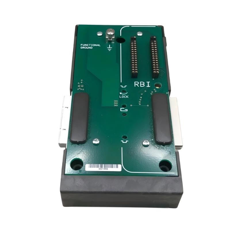
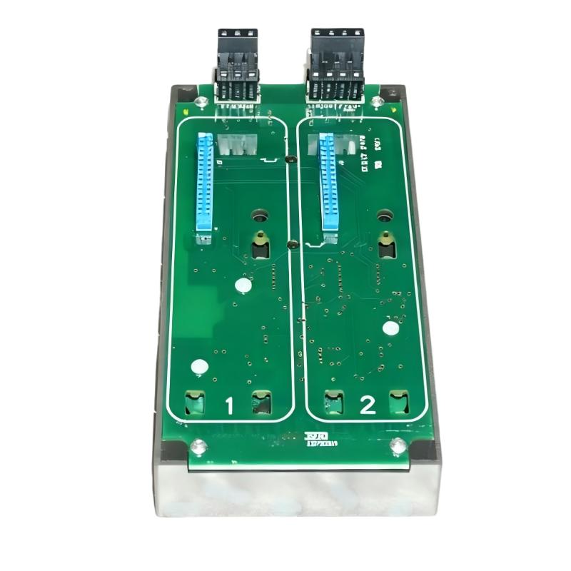
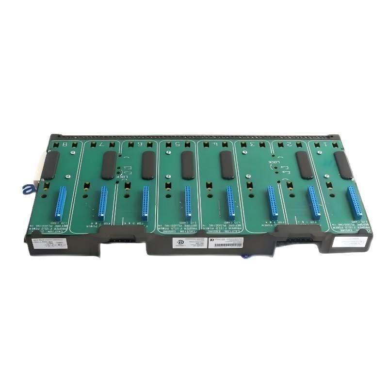
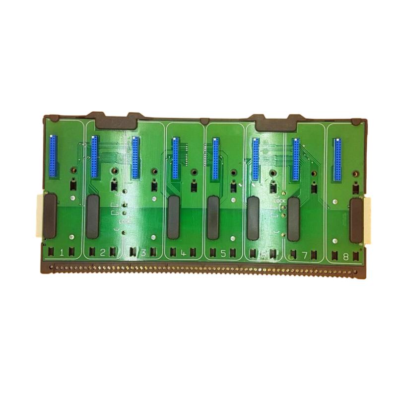
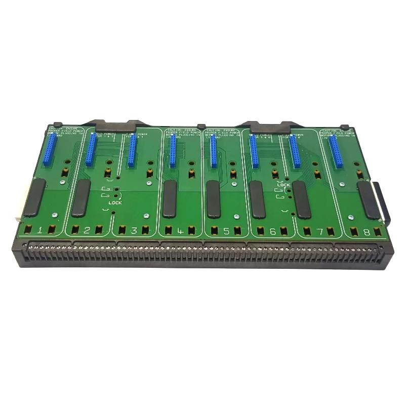
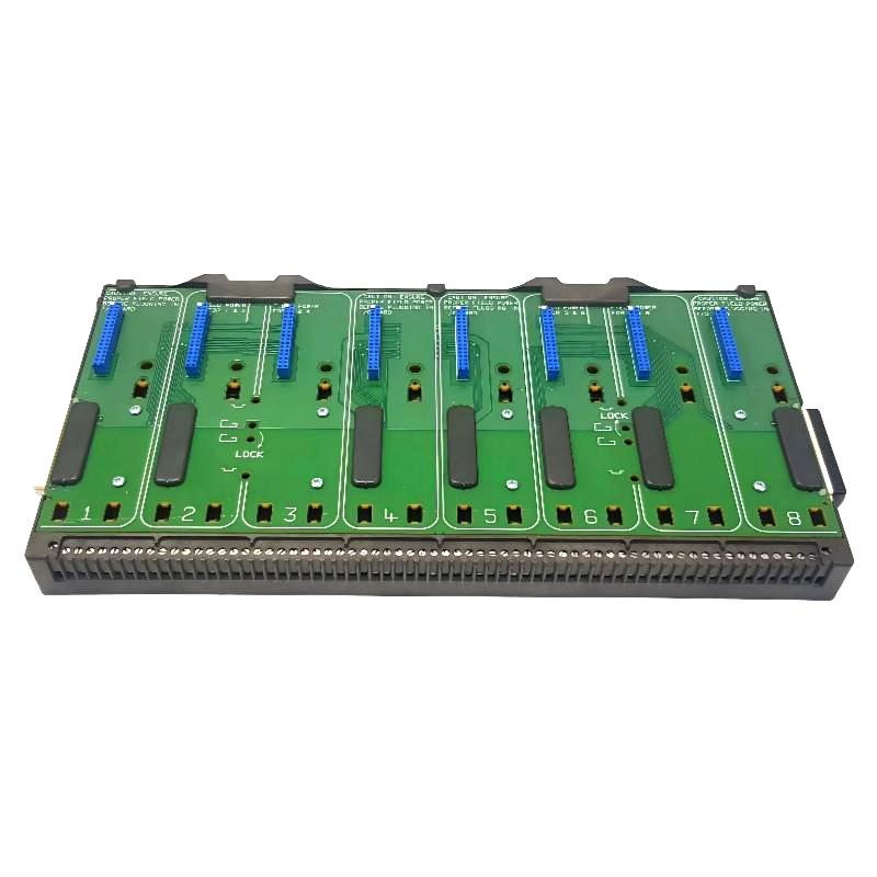
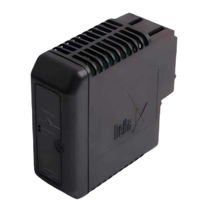
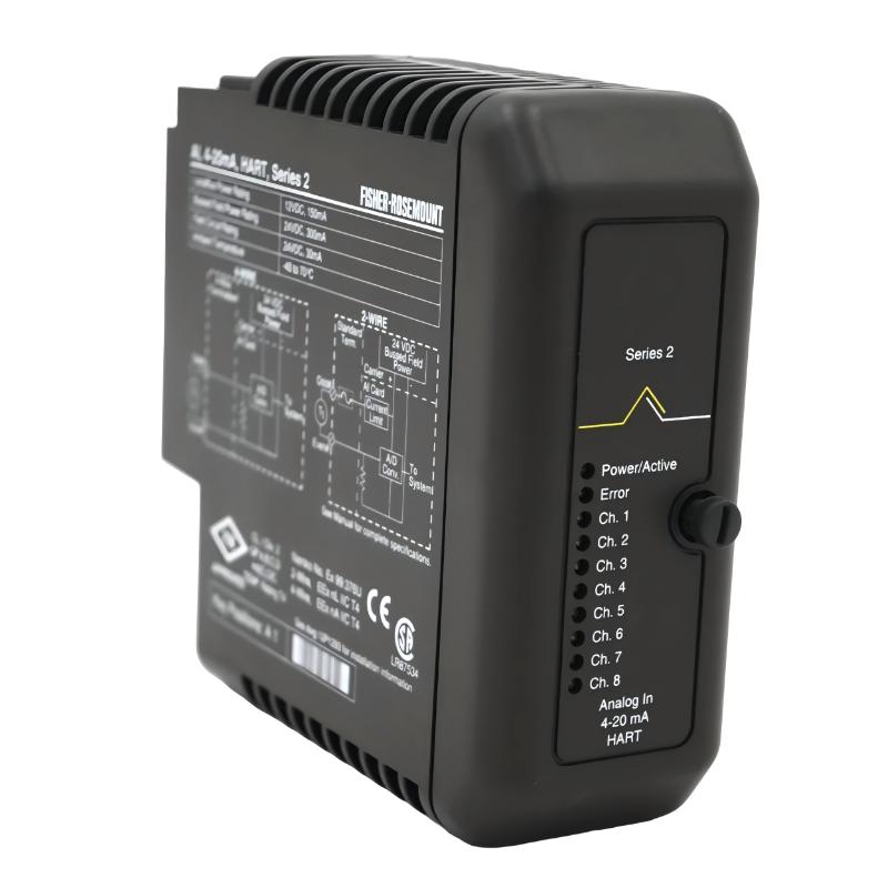
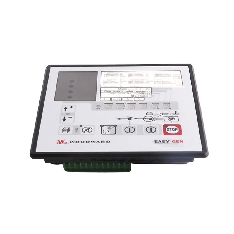
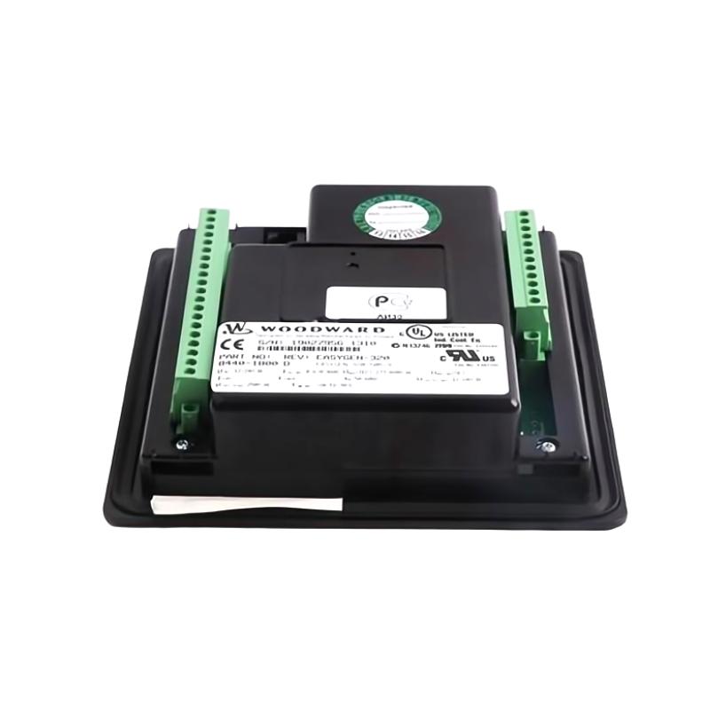
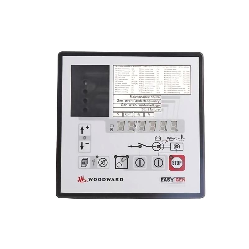
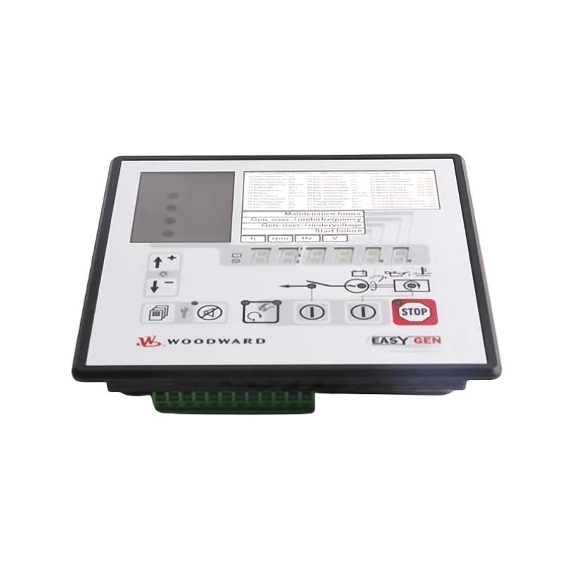
The Woodward 8440-1800 Generator Set Controller is an industrial automation controller designed for compatible engine-driven generator systems. It serves as the central control unit responsible for monitoring generator operating conditions, processing engine and electrical signals, and coordinating control outputs to ensure stable and reliable generator performance.
Within a typical power generation system, the controller forms the core of the control loop:
Engine & Generator Sensors → Woodward 8440-1800 → Control Logic → Engine / Generator Equipment → Electrical Load
The supplied physical dimensions of the Woodward 8440-1800 are 158 × 136 × 40 mm, with a weight of 1.5 kg, making it suitable for installation in industrial generator control cabinets and compact control panels.
Technical Specifications
| Parameter |
Details |
| Manufacturer |
Woodward |
| Model |
8440-1800 |
| Product Type |
Generator Set Controller |
| Primary Function |
Generator Set Monitoring and Control |
| Control Method |
Digital Microprocessor-Based Control |
| Installation Location |
Generator Control Cabinet |
| Typical Application |
Engine-Driven Generator Systems |
| Input Signals |
Engine and Generator Monitoring Signals |
| Output Signals |
Control Commands to Generator Equipment |
| Mounting Type |
Panel / Cabinet Mount |
| Dimensions |
158 × 136 × 40 mm |
| Weight |
1.5 kg |
Main Functions
The Woodward 8440-1800 continuously supervises generator operating conditions while coordinating system control functions.
Typical responsibilities include:
- Generator operating control
- Engine monitoring
- Generator electrical monitoring
- Automatic operating sequence management
- Alarm monitoring
- Protective control coordination
- System status supervision
- Operator command processing
- External system communication
- Equipment control logic execution
The actual available functions depend on the configured generator system.
Working Principle
The controller continuously collects operating information from the generator set.
Typical operating sequence:
Field Sensors
↓
8440-1800 Generator Set Controller
↓
Internal Processing
↓
Control Outputs
↓
Generator Equipment
↓
System Feedback
The controller evaluates input information and determines appropriate control actions according to the configured operating strategy.
Typical monitored parameters may include:
- Engine speed
- Oil pressure
- Coolant temperature
- Generator voltage
- Generator current
- Generator frequency
- Operating status
- Alarm conditions
- Remote commands
- Protection signals
Generator Set Control Architecture
A simplified system architecture can be represented as:
Engine Sensors
↓
Generator Sensors
↓
8440-1800 Controller
↓
Governor / Actuator / Starting System
↓
Engine
↓
Generator
↓
Electrical Distribution
↓
Load
↓
Feedback Signals
This closed-loop architecture enables continuous monitoring and control of generator operation.
Industrial Applications
The Woodward 8440-1800 is suitable for compatible applications such as:
- Diesel generator sets
- Gas engine generator systems
- Emergency power systems
- Standby generators
- Prime power stations
- Industrial utility systems
- Marine generator applications
- Mining power systems
- Oil & gas facilities
- Manufacturing plants
- Data center backup power
- Commercial power generation
Installation Guide
Step 1 – Verify Equipment Compatibility
Before installation, verify:
- Woodward 8440-1800
- Generator model compatibility
- Engine compatibility
- System voltage requirements
- Input/output requirements
- Communication configuration
- Mounting requirements
Always verify the exact model number before wiring.
Step 2 – Isolate the Generator System
Before replacing or installing the controller:
- Shut down the generator.
- Disconnect control power.
- Isolate generator output.
- Disable automatic starting.
- Apply lockout/tagout procedures.
- Verify zero energy condition.
Generator controllers can initiate automatic engine starting if not properly isolated.
Step 3 – Record Existing Connections
Before removing an existing controller:
- Photograph wiring
- Label cables
- Record terminal numbers
- Record communication wiring
- Save configuration parameters
- Record alarm settings
- Record operating setpoints
Proper documentation greatly simplifies replacement.
Step 4 – Prepare Installation Location
The supplied dimensions are:
158 × 136 × 40 mm
Weight:
1.5 kg
Ensure:
- Sufficient installation space
- Proper ventilation
- Secure mounting
- Cable routing clearance
- Maintenance accessibility
Avoid excessive heat, vibration, moisture, and conductive dust.
Step 5 – Inspect the Controller
Inspect for:
- Physical damage
- Bent connectors
- Loose hardware
- Cracked housing
- Corrosion
- Moisture
- Burn marks
- Damaged terminals
Never install a damaged controller.
Step 6 – Mount the Controller
Install the controller securely.
Verify:
- Mechanical stability
- Proper alignment
- Tight mounting hardware
- Connector accessibility
- Cable clearance
The controller should remain securely fixed during generator operation.
Step 7 – Connect Control Power
Before energizing:
Check:
- Power wiring
- Terminal polarity
- Protective grounding
- Fuse protection
- Terminal tightness
Never energize the controller before confirming correct wiring.
Step 8 – Connect Engine Inputs
Typical engine signals include:
- Engine speed
- Oil pressure
- Coolant temperature
- Fuel system status
- Engine running status
Verify every signal before startup.
Step 9 – Connect Generator Inputs
Typical generator measurements include:
- Generator voltage
- Generator current
- Generator frequency
- Electrical status
- Breaker status
Incorrect measurement wiring can affect controller decisions.
Step 10 – Connect Control Outputs
Outputs may connect to:
- Governor
- Fuel actuator
- Starting relay
- Shutdown relay
- Alarm relay
- Breaker controls
- Generator auxiliary equipment
Verify output wiring before testing.
Initial Configuration
Before commissioning, confirm:
- Generator ratings
- Engine settings
- Alarm thresholds
- Shutdown parameters
- Operating limits
- Communication parameters
- Input assignments
- Output assignments
- Control logic
Configuration errors frequently resemble hardware faults.
Commissioning Procedure
Pre-Power Inspection
Before applying power:
- Verify mounting
- Verify wiring
- Check grounding
- Inspect connectors
- Confirm configuration
- Ensure safe operating conditions
Initial Power-Up
Apply control power and verify:
- Normal startup
- Status indicators
- Controller diagnostics
- Input detection
- Communication status
- Output status
Any abnormal indication should be investigated before proceeding.
Input Verification
Verify each monitored parameter.
Check:
- Engine speed
- Temperature
- Pressure
- Generator voltage
- Current
- Frequency
- Remote commands
- Protection inputs
Compare controller readings with independent measurements whenever possible.
Output Verification
Verify controller outputs individually.
Check:
- Relay operation
- Governor response
- Actuator movement
- Alarm outputs
- Shutdown outputs
- Starting outputs
Testing should be performed under controlled conditions.
Controlled Generator Startup
After completing electrical verification:
- Confirm the generator is ready.
- Start using approved procedures.
- Monitor controller status.
- Observe engine operation.
- Verify electrical measurements.
- Monitor alarms.
- Confirm stable operation.
Generator Loading Test
Where applicable:
Gradually increase load while monitoring:
- Voltage stability
- Frequency stability
- Current
- Engine response
- Alarm status
- Controller operation
Load should be increased progressively.
Common Failure Symptoms
| Symptom |
Possible Cause |
| Controller will not power on |
Power supply problem |
| Generator will not start |
Start circuit fault |
| Unexpected shutdown |
Protection condition |
| Incorrect voltage reading |
Measurement wiring |
| Incorrect frequency |
Speed input fault |
| Communication failure |
Network wiring |
| Repeated alarms |
Sensor or configuration issue |
| Controller resets |
Power instability |
| No output response |
Output wiring or configuration |
| Generator cannot load |
Governor or control issue |
Troubleshooting Guide
Controller Does Not Start
Check:
- Incoming power
- Protective devices
- Wiring
- Connectors
- Grounding
- Internal damage
Never replace the controller before verifying external power.
Generator Will Not Start
Inspect:
- Start command
- Starting relay
- Output wiring
- Engine permissives
- Shutdown inputs
- Configuration
Follow the complete starting sequence to locate the interruption.
Generator Starts but Immediately Stops
Possible causes include:
- Active shutdown input
- Protection trip
- Sensor failure
- Configuration error
- Engine problem
Always determine the reason before resetting alarms.
Incorrect Generator Measurements
If displayed values appear incorrect:
- Measure directly using calibrated instruments.
- Inspect sensing circuits.
- Verify wiring.
- Check configuration.
- Confirm scaling.
Measurement errors are often caused by wiring rather than controller failure.
Controller Communication Failure
Inspect:
- Communication cables
- Connector condition
- Shielding
- Grounding
- Communication settings
- Connected equipment
Network faults can prevent normal controller communication.
Unexpected Controller Reset
Possible causes:
- Unstable supply voltage
- Loose wiring
- Electrical interference
- Excessive temperature
- Internal hardware issue
Record the operating condition during each reset to assist diagnosis.
Preventive Maintenance
Recommended maintenance includes:
- Visual inspection
- Connector inspection
- Wiring inspection
- Grounding verification
- Power supply inspection
- Cooling inspection
- Alarm review
- Communication verification
- Mounting inspection
- Functional testing
Routine maintenance improves long-term reliability.
Environmental Recommendations
Temperature
Maintain appropriate operating temperatures within the control cabinet.
Vibration
Inspect mounting hardware periodically, particularly on engine-mounted systems.
Moisture
Prevent exposure to condensation and water ingress.
Dust
Clean the cabinet regularly to prevent contamination.
Electromagnetic Interference
Separate signal cables from high-power wiring whenever practical.
System Integration
The 8440-1800 typically works alongside:
| Component |
Function |
| Engine Sensors |
Monitor engine condition |
| Generator Sensors |
Monitor electrical parameters |
| 8440-1800 Controller |
Central generator control |
| Governor |
Engine speed regulation |
| Starting System |
Engine starting |
| Engine |
Mechanical power source |
| Generator |
Electrical power generation |
| Protection System |
Fault protection |
| Operator Interface |
User interaction |
| Switchgear |
Electrical distribution |
Successful troubleshooting requires evaluating the complete control chain.
Controller Replacement Procedure
Before removal:
- Save configuration
- Label all wiring
- Record terminal assignments
- Photograph installation
- Record alarm history
After installation:
- Verify mounting.
- Verify wiring.
- Apply power.
- Verify inputs.
- Verify outputs.
- Test communication.
- Perform startup test.
- Verify stable operation.
- Conduct controlled load testing.
Key Advantages
- Compact industrial design
- Centralized generator-set control
- Reliable engine and generator monitoring
- Supports multiple field inputs
- Integrates with compatible generator systems
- Suitable for standby and prime power applications
- Compact dimensions of 158 × 136 × 40 mm
- Lightweight design at 1.5 kg
- Designed for industrial control cabinet installation
Technical FAQs
What is the Woodward 8440-1800?
The Woodward 8440-1800 is a Generator Set Controller used in compatible industrial generator systems.
What is its primary function?
It monitors engine and generator operating conditions while coordinating generator-set control functions.
What equipment can it control?
Depending on system configuration, it may interact with governors, actuators, relays, protection systems, and generator equipment.
What are its dimensions?
The supplied dimensions are 158 × 136 × 40 mm.
What is its weight?
The supplied weight is 1.5 kg.
Why won’t the generator start?
Possible causes include missing start commands, configuration errors, protection conditions, power supply problems, or engine-related faults.
Why are the displayed electrical values incorrect?
Incorrect sensing wiring, scaling configuration, or sensor problems are common causes.
Why does the controller reset?
Unstable power, loose wiring, excessive electrical noise, or hardware issues may cause unexpected resets.
What should be checked before replacing the controller?
Always verify external power, wiring, sensors, configuration, communication, and connected equipment before assuming controller failure.
What should be tested after installation?
Power, inputs, outputs, communication, alarms, startup sequence, and generator load response should all be verified before returning the system to service.
Conclusion
The Woodward 8440-1800 Generator Set Controller is a compact digital control solution designed for compatible engine-driven generator applications. By continuously monitoring engine conditions, electrical measurements, and operating status, it helps coordinate generator operation while supporting reliable and efficient system performance.
Proper installation requires careful verification of power wiring, engine inputs, generator measurements, control outputs, grounding, communication, and configuration. During commissioning, each stage—from power-up and signal verification to controlled startup and load testing—should be completed methodically to ensure dependable operation.
For troubleshooting, always evaluate the complete control path:
Sensors → 8440-1800 Controller → Control Outputs → Engine / Generator → Electrical Load
Following this systematic approach makes it easier to distinguish controller issues from faults caused by sensors, wiring, actuators, protection devices, or other generator-set components, improving maintenance efficiency and reducing unnecessary hardware replacement.