Product Overview
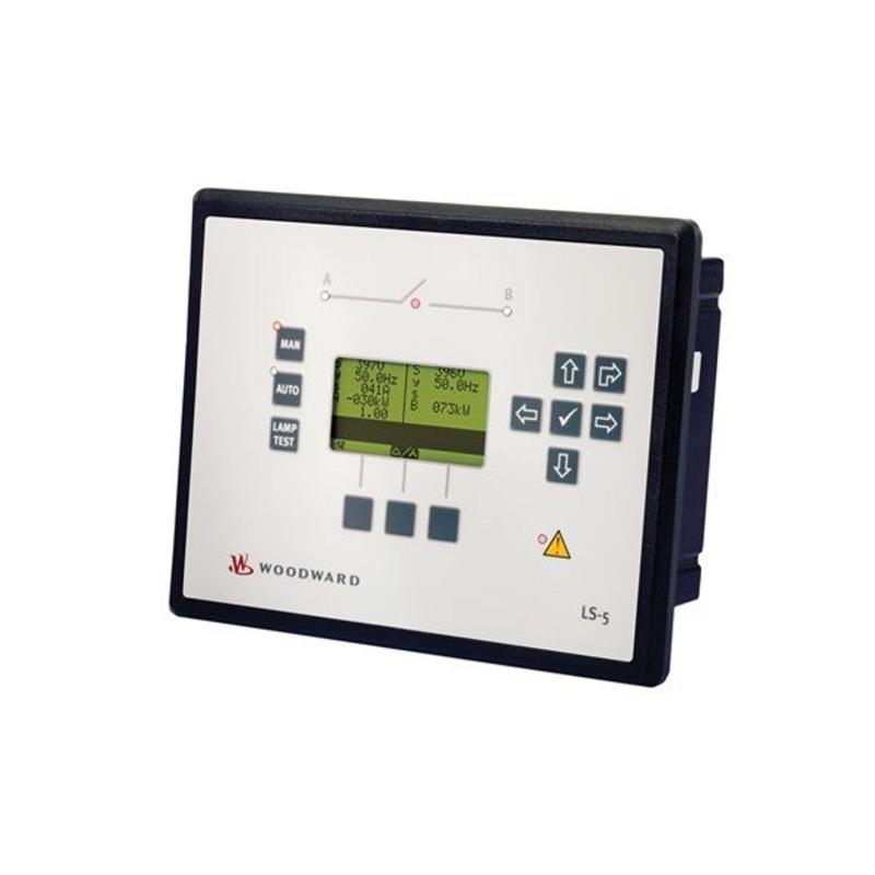
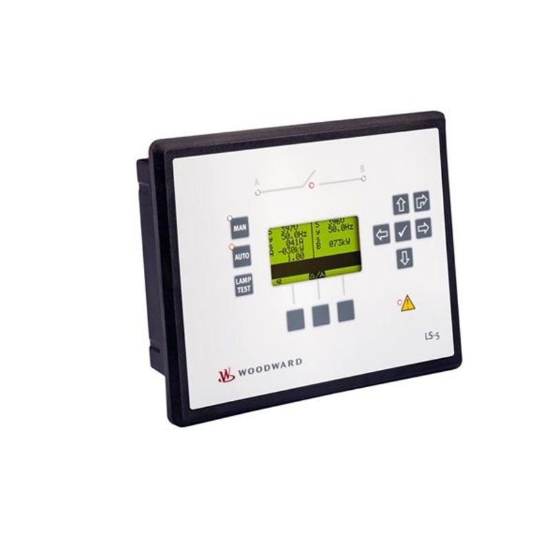
The Woodward 8440-2150A Controller is an industrial digital controller intended for compatible engine, generator, turbine, and equipment automation systems. It provides a centralized platform for acquiring field signals, processing operating conditions, executing configured control logic, and transmitting control commands to connected devices.
In a typical industrial control application, the controller sits between the field instrumentation and the controlled equipment:
Field Sensors → Woodward 8440-2150A Controller → Actuators / Relays → Controlled Equipment → Feedback
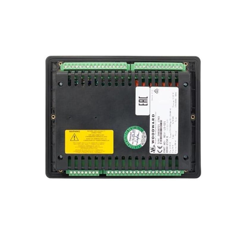
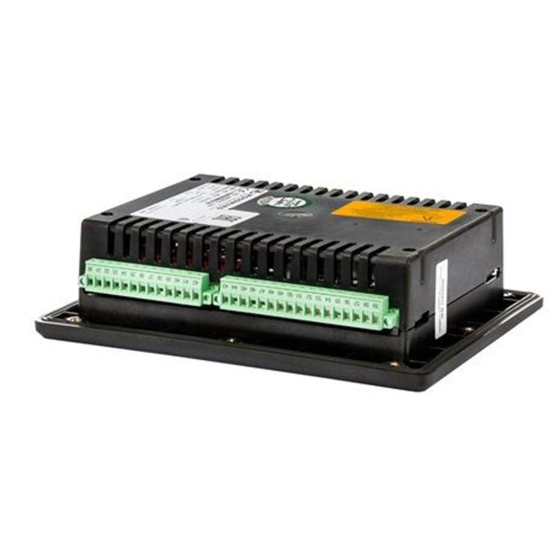
The supplied dimensions of the Woodward 8440-2150A are 240 × 172 × 65 mm, with a weight of 1.5 kg. Its compact form factor allows integration into industrial control cabinets and equipment panels where space and service accessibility are important considerations.
Technical Specifications
| Parameter |
Details |
| Manufacturer |
Woodward |
| Model |
8440-2150A |
| Product Type |
Industrial Controller |
| Primary Function |
Equipment Monitoring and Control |
| Control Technology |
Digital Microprocessor-Based Control |
| Typical Application |
Engine, Generator, Turbine and Industrial Automation |
| Input Signals |
Analog and Digital Field Signals |
| Output Signals |
Control Signals to Connected Equipment |
| Installation |
Industrial Control Cabinet |
| Mounting |
Panel / Cabinet Mount |
| Dimensions |
240 × 172 × 65 mm |
| Weight |
1.5 kg |
Main Functions
The Woodward 8440-2150A can serve as a central control component within a compatible automation system.
Typical responsibilities include:
- Field signal acquisition
- Equipment status monitoring
- Digital control logic execution
- Analog process monitoring
- Output command generation
- Alarm supervision
- Protection coordination
- Operating sequence management
- Diagnostic monitoring
- Communication with other automation devices
The exact functions available in a particular installation depend on the system configuration.
Working Principle
The controller receives operating information from connected sensors and equipment, processes that information according to its programmed logic, and produces corresponding output commands.
A simplified sequence is:
Sensors / Field Devices
↓
8440-2150A Controller
↓
Signal Processing
↓
Control Logic
↓
Output Commands
↓
Actuators / Equipment
↓
Process Feedback
The controller continuously repeats this process during operation, allowing the system to respond to changing operating conditions.
Typical monitored variables may include:
- Pressure
- Temperature
- Speed
- Voltage
- Current
- Frequency
- Equipment status
- Alarm signals
- Interlocks
- Remote commands
Role in Industrial Control Systems
The Woodward 8440-2150A can perform several important roles within a control architecture.
Signal Processing
It receives information from sensors and field devices and makes that information available to the control logic.
Control Execution
The controller processes operating conditions and generates commands according to configured logic.
Equipment Supervision
Operating parameters can be monitored continuously to identify abnormal conditions.
Alarm Management
Abnormal signals can be used to trigger alarm or protective functions when configured by the system designer.
System Integration
The controller can form part of a larger automation architecture containing operator interfaces, supervisory systems, protection equipment, and field devices.
Typical Industrial Applications
The Woodward 8440-2150A may be used in compatible applications such as:
- Generator automation
- Diesel engine control
- Gas engine systems
- Turbine control
- Compressor control
- Pumping systems
- Power generation equipment
- Oil and gas installations
- Marine machinery
- Industrial process equipment
- Utility systems
- Manufacturing automation
Installation Guide
Step 1 – Verify the Controller
Before installation, confirm:
- Model number: 8440-2150A
- Required system compatibility
- Power supply requirements
- Input configuration
- Output configuration
- Communication requirements
- Mechanical mounting requirements
Do not rely only on physical similarity when selecting a replacement controller.
Step 2 – Shut Down and Isolate the System
Before working on the controller:
- Stop the associated equipment.
- Disconnect control power.
- Disable automatic starting or operation.
- Isolate relevant energy sources.
- Apply appropriate lockout/tagout procedures.
- Verify that the system is safe to service.
This is especially important where the controller can issue commands to engines, generators, actuators, or other machinery.
Step 3 – Document Existing Connections
Before removing an existing unit:
- Photograph the installation.
- Label every cable.
- Record terminal assignments.
- Record I/O connections.
- Document communication wiring.
- Save configuration information.
- Record important operating parameters.
This information can prevent wiring mistakes during replacement.
Step 4 – Prepare the Mounting Location
The supplied controller dimensions are:
240 × 172 × 65 mm
Weight:
1.5 kg
Allow sufficient space for:
- Mounting hardware
- Cable routing
- Connector access
- Ventilation
- Inspection
- Future replacement
The controller should not be installed where it is exposed directly to excessive heat, water, condensation, or conductive dust.
Step 5 – Inspect the Controller
Before mounting, inspect:
- Housing
- Connectors
- Terminals
- Mounting points
- Wiring interfaces
- Signs of corrosion
- Signs of impact
- Moisture contamination
- Burn or overheating marks
Any physical damage should be investigated before installation.
Step 6 – Mount the Controller
Secure the controller in the designated cabinet or panel location.
Check:
- Mechanical alignment
- Mounting security
- Connector accessibility
- Cable clearance
- Cabinet ventilation
- Protection against vibration
Loose mounting can cause mechanical stress on connectors and wiring.
Step 7 – Connect Power
Before energizing the controller:
- Verify supply voltage.
- Check power wiring.
- Confirm polarity where applicable.
- Verify grounding.
- Check protective devices.
- Tighten terminals appropriately.
Do not apply power until the complete power circuit has been inspected.
Step 8 – Connect Field Inputs
Depending on the application, field inputs may include:
Analog Signals
- Temperature
- Pressure
- Speed
- Flow
- Level
- Electrical measurements
Digital Signals
- Running status
- Alarm contacts
- Interlocks
- Limit switches
- Remote commands
- Protection signals
Each input should be checked against the system wiring documentation.
Step 9 – Connect Outputs
Output circuits may interface with:
- Relays
- Contactors
- Solenoid valves
- Actuators
- Governors
- Motor control equipment
- Alarm circuits
- Shutdown circuits
Verify each output connection before functional testing.
Step 10 – Verify Communication
If the system includes communication with other equipment, verify:
- Communication cables
- Connector condition
- Network configuration
- Device addressing
- Controller settings
- Connected equipment
Communication should be confirmed before performing full operational testing.
Initial Configuration
Before commissioning, verify the controller’s configured parameters.
Important categories may include:
- Input scaling
- Output assignments
- Alarm limits
- Protection parameters
- Operating modes
- Control parameters
- Communication settings
- Equipment ratings
A configuration error can produce symptoms that appear to be hardware faults.
Commissioning Procedure
Pre-Power Inspection
Before applying control power:
- Check mounting.
- Inspect all wiring.
- Verify grounding.
- Confirm connector seating.
- Verify communication connections.
- Confirm configuration information.
Initial Power-Up
Apply power and monitor the controller for:
- Normal startup
- Status indications
- Diagnostic conditions
- Communication status
- Input recognition
- Output readiness
Do not proceed with equipment startup if unexpected faults are present.
Input Testing
Verify each connected field input.
Check:
- Sensor response
- Signal stability
- Correct scaling
- Wiring integrity
- Controller indication
Where appropriate, compare controller readings with independent test equipment.
Output Testing
Test outputs individually under safe conditions.
Verify:
- Relay operation
- Actuator response
- Alarm output
- Shutdown output
- Control response
Never perform output testing without considering the effect on connected machinery.
Functional Test
Verify:
- Control sequences
- Interlocks
- Alarm behavior
- Protection responses
- Communication
- Equipment response
- Operator commands
The complete system should respond predictably to each test condition.
Common Failure Symptoms
| Symptom |
Possible Cause |
| Controller does not power on |
Power supply or wiring fault |
| Controller loses communication |
Network or configuration problem |
| Incorrect sensor value |
Sensor, wiring or scaling fault |
| Output does not operate |
Output wiring or configuration issue |
| Repeated alarms |
Sensor or process abnormality |
| Unexpected shutdown |
Protection or interlock condition |
| Controller resets |
Power instability or environmental issue |
| Equipment does not respond |
External actuator or equipment fault |
| Intermittent operation |
Loose connection or electrical interference |
| Incorrect operating sequence |
Configuration or control logic issue |
Troubleshooting Guide
Controller Does Not Power On
Start with the external power circuit.
Check:
- Incoming supply.
- Protective fuse or breaker.
- Power wiring.
- Grounding.
- Connectors.
- Terminal condition.
- Controller condition.
If the external power supply is unstable, replacing the controller may not solve the problem.
Communication Failure
If the controller cannot communicate with another device:
- Inspect communication wiring.
- Check connectors.
- Verify device addressing.
- Confirm communication parameters.
- Check the connected device.
- Inspect network infrastructure.
A communication fault does not automatically indicate controller hardware failure.
Incorrect Input Readings
When a process value is incorrect:
First verify the field signal → then wiring → then scaling → then configuration → then controller hardware.
Check:
- Sensor output
- Signal wiring
- Terminal connections
- Input scaling
- Configuration
- Independent measurement
This approach helps prevent unnecessary controller replacement.
Outputs Not Operating
Check:
- Output configuration
- Wiring
- Interlocks
- Operating mode
- Control logic
- External equipment
- Actuator condition
An output may remain inactive because the system intentionally prevents operation under current conditions.
Unexpected Shutdown
Investigate:
- Protection inputs
- Alarm history
- Sensor values
- External shutdown commands
- Interlocks
- Configuration
- Connected equipment
Identify the initiating condition before restarting.
Controller Repeatedly Resets
Possible causes include:
- Unstable control power
- Loose power connections
- Electrical interference
- Excessive cabinet temperature
- Wiring problems
- Hardware malfunction
Record the time and operating conditions of each reset to identify patterns.
Preventive Maintenance
Recommended maintenance activities include:
- Visual inspection
- Connector inspection
- Wiring inspection
- Grounding verification
- Communication checks
- Functional testing
- Alarm review
- Cabinet cleaning
- Cooling inspection
- Mounting inspection
Maintenance should be performed according to the requirements of the complete system.
Environmental Considerations
Temperature
Maintain suitable cabinet temperatures and prevent excessive heat accumulation.
Moisture
Protect the controller against condensation and water ingress.
Dust
Keep the control cabinet clean, particularly in industrial environments where conductive dust may be present.
Vibration
Check mounting hardware and connectors regularly in equipment exposed to continuous mechanical vibration.
Electrical Noise
Route low-level signal and communication wiring away from high-current and high-voltage cables whenever practical.
System Integration
A typical installation may contain:
| Component |
Function |
| Field Sensors |
Collect process information |
| Woodward 8440-2150A |
Central control and processing |
| Actuators |
Execute control commands |
| Protection Devices |
Protect equipment |
| Operator Interface |
Provide human-machine interaction |
| Communication Network |
Exchange system data |
| Engine / Generator / Turbine |
Controlled equipment |
| Supervisory System |
Monitoring and higher-level control |
The controller should therefore be diagnosed as part of the complete system rather than as an isolated component.
Controller Replacement Procedure
Before Removal
Record:
- Controller model
- Wiring arrangement
- Terminal assignments
- I/O configuration
- Communication settings
- Operating parameters
- Alarm configuration
Save all available configuration information.
After Installation
Follow this sequence:
- Secure the controller.
- Reconnect power.
- Reconnect field inputs.
- Reconnect outputs.
- Verify communication.
- Inspect all connections.
- Apply power.
- Check diagnostics.
- Test inputs.
- Test outputs.
- Verify control logic.
- Perform controlled equipment startup.
Key Advantages
- Compact industrial controller design
- Centralized equipment monitoring
- Digital control and signal processing
- Suitable for demanding automation applications
- Supports integration with field devices
- Suitable for engine and power-generation systems
- Compact 240 × 172 × 65 mm form factor
- 1.5 kg supplied weight
- Practical for industrial control cabinet installation
Technical FAQs
What is the Woodward 8440-2150A?
The Woodward 8440-2150A is an industrial Controller designed for compatible engine, generator, turbine, and automation applications.
What does the controller do?
It receives field information, processes operating conditions, executes configured control logic, and generates commands for connected equipment.
Where is the 8440-2150A installed?
It can be installed in a suitable industrial control cabinet or equipment panel with adequate ventilation, mechanical support, and cable clearance.
What are the dimensions of the controller?
The supplied dimensions are 240 × 172 × 65 mm.
How much does it weigh?
The supplied weight is 1.5 kg.
Why might the controller show incorrect process values?
Possible causes include defective sensors, incorrect wiring, poor connections, incorrect input scaling, or configuration problems.
Why might communication fail?
Communication problems can result from damaged cables, loose connectors, incorrect settings, addressing problems, or faults in connected equipment.
Why might the controller reset during operation?
Power instability, electrical interference, excessive temperature, loose connections, or hardware problems can cause unexpected resets.
Should the controller be replaced immediately after a fault?
No. External power, field wiring, sensors, communication, configuration, and connected equipment should be checked first.
What should be verified after replacing the controller?
Verify power-up, communication, input signals, outputs, alarms, interlocks, control sequences, and the response of the connected equipment.
Conclusion
The Woodward 8440-2150A Controller provides a centralized digital control platform for compatible industrial automation, engine, generator, and power-generation systems. Its primary role is to process field information and coordinate control commands, allowing connected equipment to operate according to configured control strategies.
With dimensions of 240 × 172 × 65 mm and a weight of 1.5 kg, the controller can be integrated into appropriately designed industrial control cabinets while maintaining reasonable installation and maintenance accessibility.
For reliable commissioning, particular attention should be given to power supply, grounding, field wiring, input scaling, output connections, communication, configuration, and interlocks. For troubleshooting, the most effective approach is to trace the complete signal path:
Field Device → 8440-2150A Controller → Output → Actuator / Equipment → Feedback
This systematic method helps technicians separate controller faults from external wiring, sensor, communication, actuator, configuration, and process problems, reducing unnecessary replacement and improving overall maintenance efficiency.