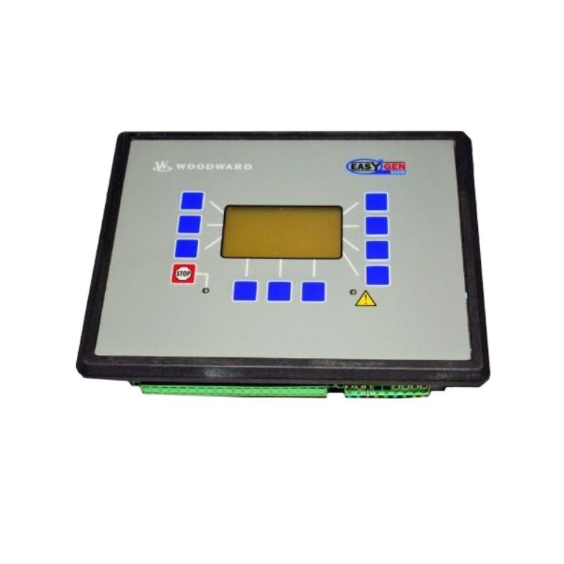
Product Overview
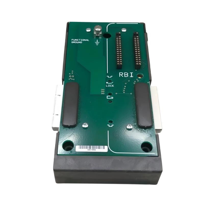
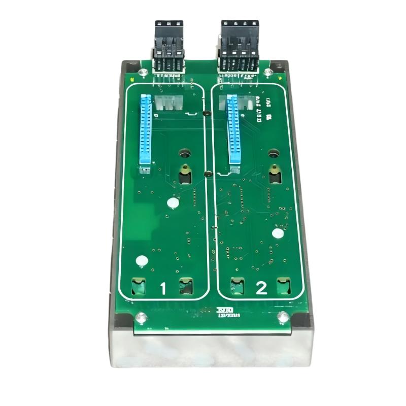
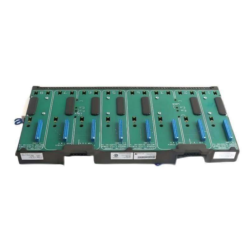
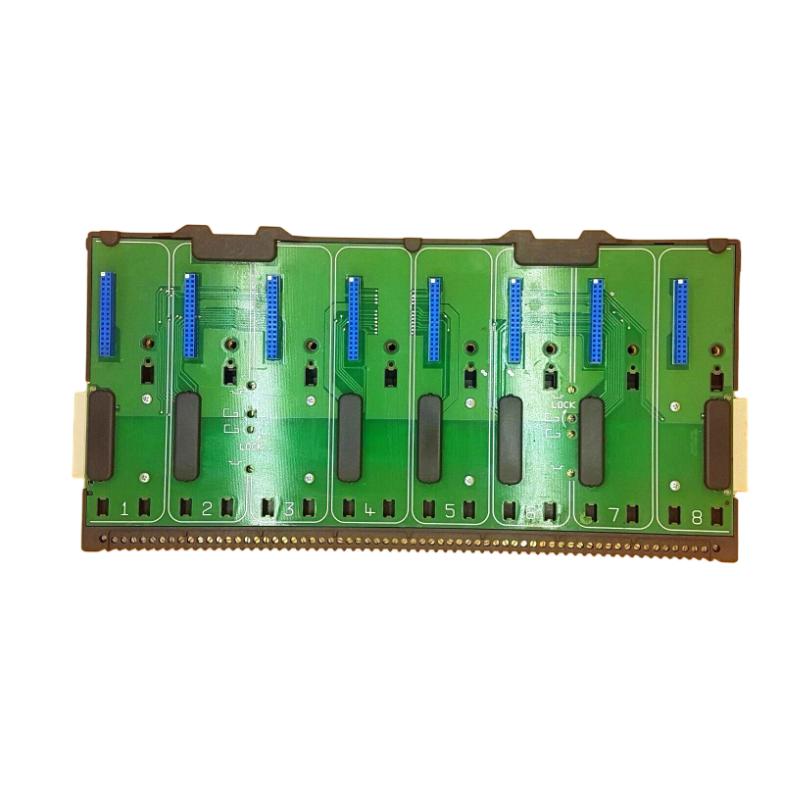
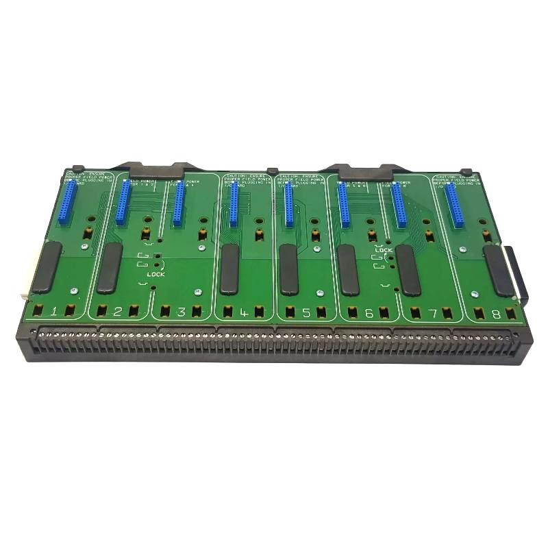
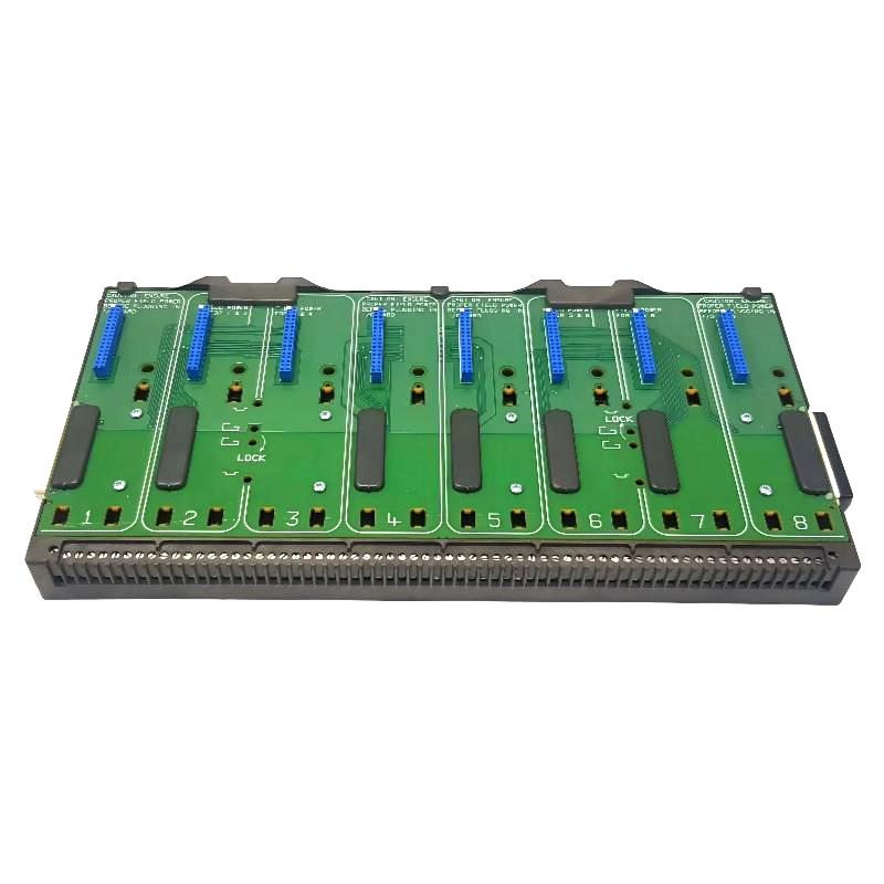
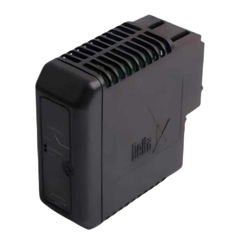
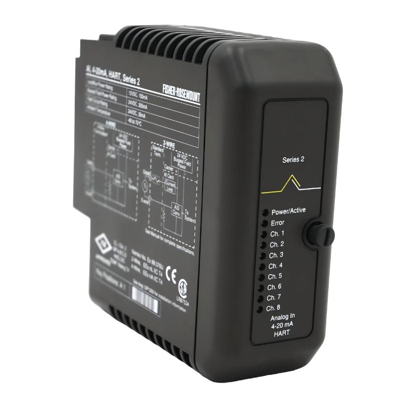
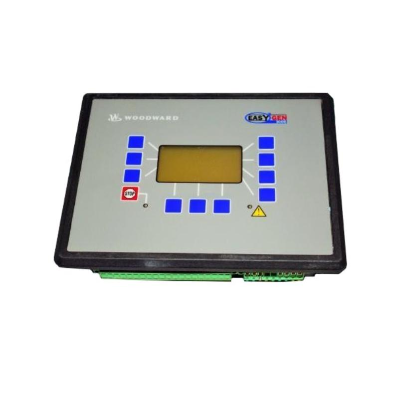
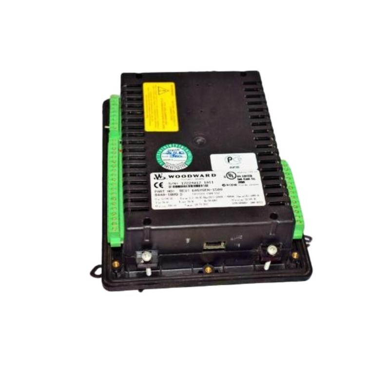
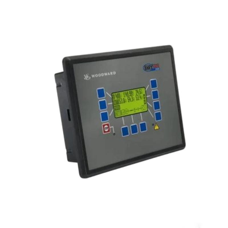
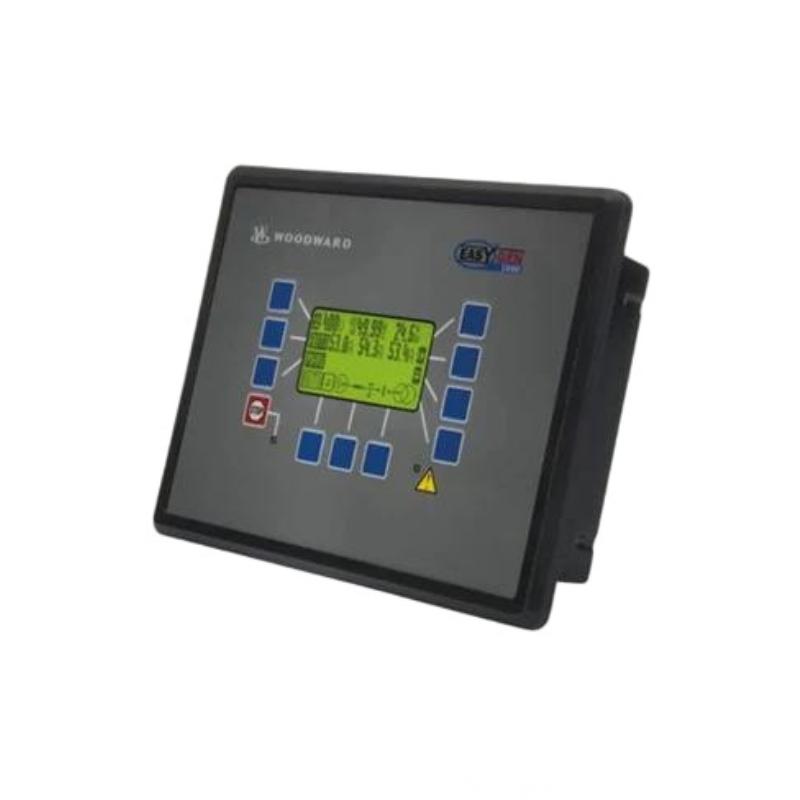
The Woodward 8440-1750 Generator Set Controller is an industrial control component designed for compatible generator-set applications. As a generator-set controller, it can serve as a central coordination point between the engine, generator, sensors, control outputs, protection functions, and operator commands.
A simplified generator-set control architecture is:
Engine & Generator Signals → 8440-1750 → Control Outputs → Engine / Generator System
The controller can process operating information and, according to the configured system strategy, coordinate functions associated with generator-set operation.
The supplied physical specifications for the Woodward 8440-1750 are 300 × 200 × 60 mm, with a stated weight of 1.2 kg.
Because generator-set controllers can be associated with starting, stopping, operating, and protection functions, installation and commissioning should be carried out under controlled conditions and according to the applicable equipment documentation.
Technical Specifications
| Parameter |
Details |
| Manufacturer |
Woodward |
| Model |
8440-1750 |
| Product Type |
Generator Set Controller |
| Main Function |
Generator Set Control |
| Control Role |
Monitoring, Sequencing and Control |
| Application |
Engine-Driven Generator Sets |
| Input Function |
Engine, Generator and External Control Signals |
| Output Function |
Control Commands to Compatible Equipment |
| Installation |
Industrial Control Cabinet / Generator Control Panel |
| Dimensions |
300 × 200 × 60 mm |
| Weight |
1.2 kg |
Function and Working Principle
The 8440-1750 operates as part of a generator-set control system.
A simplified control loop is:
Operating Sensors
↓
8440-1750 Generator Set Controller
↓
Engine / Generator Control Devices
↓
Generator Set
↓
Electrical Load
↓
Feedback Signals
The controller evaluates available information and applies the configured control strategy.
Depending on the system design, relevant information may include:
- Engine speed
- Engine temperature
- Engine pressure
- Generator voltage
- Generator frequency
- Generator current
- Operating status
- Alarm conditions
- Start/stop commands
- External control signals
The controller can then provide appropriate commands to compatible control devices.
Role in Generator Set Control
A generator-set controller can coordinate multiple aspects of generator operation.
Typical control areas include:
Starting and Stopping
The controller can participate in the generator-set startup and shutdown sequence where configured for those functions.
Operating Monitoring
Engine and generator conditions can be monitored through connected inputs.
Control Coordination
The controller can coordinate control outputs with the generator-set operating state.
Alarm Handling
Abnormal conditions can be detected through configured inputs and control logic.
Protection Functions
Where supported by the complete system, protection-related conditions can be incorporated into generator-set control.
External Control
The generator set may receive commands from an operator interface or external control system.
Generator Set Control Architecture
A typical system can be represented as:
Engine Sensors + Generator Measurements + External Commands
↓
8440-1750
↓
Control Logic
↓
Starting / Fuel / Governor / Actuator / Other Control Devices
↓
Engine
↓
Generator
↓
Electrical Load
↓
Feedback
This architecture makes it important to troubleshoot the entire system rather than assuming that every abnormal condition originates inside the controller.
Industrial Applications
The Woodward 8440-1750 may be suitable for compatible applications involving:
- Diesel generator sets
- Gas engine generator sets
- Standby generators
- Prime-power generator sets
- Industrial power-generation systems
- Emergency power systems
- Engine-driven generators
- Industrial generator control panels
- Automated generator systems
- Distributed power equipment
Installation Guide
Step 1 – Verify the Controller
Before installation, confirm:
- Woodward 8440-1750
- Complete model identification
- Generator-set compatibility
- Control-power requirements
- Input requirements
- Output requirements
- Communication connections
- Mounting arrangement
- Required control functions
Physical similarity with another controller does not establish electrical or functional compatibility.
Step 2 – Isolate the Generator Set
Before installation or replacement:
- Stop the generator set.
- Disconnect applicable control power.
- Prevent automatic starting.
- Isolate the generator from the relevant electrical system.
- Apply appropriate lockout/tagout procedures.
- Address stored electrical and mechanical energy.
- Verify that the generator cannot start unexpectedly.
This step is especially important because generator-set controllers may participate in automatic starting sequences.
Step 3 – Document Existing Wiring
Before removing an existing controller:
- Photograph the complete installation.
- Record terminal numbers.
- Label each conductor.
- Identify control-power wiring.
- Identify engine inputs.
- Identify generator measurement circuits.
- Identify output circuits.
- Record communication wiring.
- Record grounding connections.
- Save existing configuration information where applicable.
A detailed wiring record can significantly reduce replacement errors.
Step 4 – Inspect the Mounting Location
The supplied dimensions are:
300 × 200 × 60 mm
The supplied weight is:
1.2 kg
Ensure the control cabinet provides sufficient physical space and mechanical support.
Allow room for:
- Cable routing
- Connectors
- Ventilation
- Inspection
- Maintenance
- Controller removal
The mounting location should also be protected from excessive vibration, heat, moisture, and contamination.
Step 5 – Inspect the Controller
Before installation, inspect the 8440-1750 for:
- Housing damage
- Cracks
- Damaged terminals
- Bent contacts
- Corrosion
- Contamination
- Signs of overheating
- Loose hardware
Verify the model number before connecting the controller.
Step 6 – Mount the Controller
Secure the controller firmly in the approved location.
Check:
- Mounting alignment
- Fastener security
- Mechanical support
- Connector accessibility
- Cable clearance
- Ventilation
- Vibration resistance
The controller should remain securely mounted during generator-set operation.
Step 7 – Connect Control Power
Before applying power, verify:
- Correct control-power circuit
- Terminal identification
- Polarity where applicable
- Protective devices
- Grounding
- Terminal tightness
Do not energize the controller until the power circuit has been inspected.
Step 8 – Connect Engine Signals
Connect the applicable engine-related signals according to the system wiring.
Depending on the configuration, these may include:
- Speed
- Temperature
- Pressure
- Running status
- Shutdown status
- Other engine operating signals
Check each circuit for correct terminal assignment and signal integrity.
Step 9 – Connect Generator Signals
Generator-related circuits should be connected according to the approved system design.
Possible signals include:
- Voltage measurement
- Current measurement
- Frequency
- Generator status
- Breaker or switchgear status
- Other electrical-system information
Incorrect generator measurement wiring can result in incorrect control decisions.
Step 10 – Connect Control Outputs
Output circuits may interface with:
- Starting equipment
- Engine control devices
- Governors
- Actuators
- Relays
- Contactors
- Switchgear
- Other generator-set control equipment
Verify output assignments before performing functional tests.
Initial Configuration
Before commissioning, verify the applicable configuration.
Check where relevant:
- Generator-set parameters
- Engine parameters
- Input assignments
- Output assignments
- Start/stop logic
- Alarm settings
- Shutdown conditions
- Control modes
- Operating limits
- Communication settings
Incorrect configuration can create symptoms that resemble hardware failure.
Commissioning Procedure
Pre-Power Inspection
Before applying control power:
- Verify controller mounting.
- Check power wiring.
- Check engine inputs.
- Check generator measurement circuits.
- Check outputs.
- Verify grounding.
- Inspect connectors.
- Confirm configuration.
- Prevent unintended generator startup.
Power-Up Test
Apply control power under safe conditions.
Check:
- Controller startup behavior
- Status indications
- Diagnostic information
- Communication status
- Input availability
- Expected output states
If an unexpected output could start or energize the generator set, stop the commissioning procedure and investigate.
Input Verification
Verify each important input independently.
Engine Inputs
Check:
- Speed
- Temperature
- Pressure
- Running status
- Shutdown signals
Generator Inputs
Check:
- Voltage
- Frequency
- Current
- Electrical status
External Inputs
Check:
- Start command
- Stop command
- Remote control
- Permissives
- Emergency or protection signals
Where appropriate, compare controller readings with independent measurements.
Output Verification
Perform controlled output tests.
Verify:
- Correct output channel
- Correct sequence
- Expected command
- Relay response
- Actuator response
- Starting-system response
- Safe return condition
Avoid uncontrolled tests that could cause the generator set to start or change operating conditions unexpectedly.
Generator Set Startup Test
After electrical checks have been completed:
- Confirm the generator set is ready.
- Confirm automatic-start conditions are controlled.
- Initiate the approved startup sequence.
- Monitor engine speed.
- Monitor generator voltage.
- Monitor generator frequency.
- Observe controller status.
- Check alarms.
- Verify stable operation.
Do not proceed to higher-load testing if fundamental operating parameters are abnormal.
Load Verification
Where applicable, perform controlled load tests.
Monitor:
- Generator voltage
- Frequency
- Current
- Load level
- Engine speed
- Temperature
- Pressure
- Controller status
- Alarm conditions
Load should be increased gradually according to the applicable commissioning procedure.
Common Failure Symptoms
| Symptom |
Possible Cause |
| Controller does not power up |
Control-power or wiring problem |
| Generator does not start |
Start circuit, permissive or configuration issue |
| Generator starts unexpectedly |
External command or configuration issue |
| Incorrect voltage reading |
Measurement circuit or configuration |
| Incorrect frequency |
Speed signal or configuration |
| Generator fails to accept load |
Control, protection or electrical-system issue |
| Controller resets |
Power instability or hardware fault |
| Communication failure |
Cable or configuration issue |
| Repeated alarms |
Sensor, wiring or configuration problem |
| Unexpected shutdown |
Protection input or control condition |
Troubleshooting Guide
Controller Does Not Power Up
Check:
- Control-power supply.
- Protective devices.
- Power wiring.
- Terminals.
- Grounding.
- Connectors.
- Controller condition.
Verify the external power source before replacing the controller.
Generator Set Does Not Start
Trace the startup chain:
Start Command → Controller → Permissive → Starting Control → Engine
Check:
- Start command
- Control power
- Start permissives
- Shutdown conditions
- Configuration
- Output circuit
- Starting equipment
- Engine condition
If the controller does not recognize the start command, investigate the input circuit first.
Generator Starts but Shuts Down
Check:
- Active alarms
- Engine speed
- Oil or pressure-related signals where applicable
- Temperature signals
- Generator voltage
- Frequency
- Shutdown inputs
- Controller configuration
Do not repeatedly reset shutdown conditions without determining the underlying cause.
Incorrect Generator Voltage Reading
If the controller indicates an incorrect voltage:
- Measure the generator independently.
- Compare the actual value with the controller indication.
- Inspect measurement wiring.
- Check terminals.
- Verify signal configuration.
- Check scaling.
- Inspect associated measurement circuits.
If the actual generator voltage is normal but the controller indication is incorrect, focus on the measurement path.
Incorrect Frequency or Speed Reading
Check:
- Speed sensor
- Sensor wiring
- Signal quality
- Input terminals
- Configuration
- Actual engine speed
Incorrect speed information can affect startup, operating control, and protection-related functions.
Generator Does Not Accept Load
Possible causes include:
- Incorrect control configuration
- Load-control issue
- Governor response
- Generator electrical conditions
- Protection or permissive condition
- Switchgear problem
- External control-system issue
Trace the complete path from the controller command to the engine, generator, and electrical load.
Controller Resets During Operation
Possible causes include:
- Unstable control power
- Loose terminals
- Electrical interference
- Damaged wiring
- Excessive temperature
- Internal hardware fault
If possible, determine whether the reset occurs simultaneously with a power disturbance or another generator event.
Communication Troubleshooting
If the controller communicates with another control device, inspect:
- Communication cables
- Connectors
- Grounding
- Shielding
- Configuration
- Network settings
- External communication equipment
A communication problem can make a healthy controller appear unavailable.
Alarm and Protection Troubleshooting
When an alarm or shutdown occurs:
- Record the alarm.
- Identify the associated condition.
- Check the physical generator-set condition.
- Verify the corresponding sensor or input.
- Check wiring.
- Review configuration.
- Determine whether the condition is active or historical.
- Correct the underlying issue before resetting protection.
This approach helps prevent repeated nuisance resets and unnecessary controller replacement.
Preventive Maintenance
Recommended maintenance activities include:
- Controller visual inspection
- Terminal inspection
- Connector inspection
- Control-power verification
- Engine-signal inspection
- Generator-signal inspection
- Output-circuit inspection
- Communication checks
- Grounding inspection
- Cabinet ventilation inspection
- Mounting-hardware inspection
- Alarm-history review
Regular inspection is especially useful in generator environments where vibration, heat, and electrical switching can stress control equipment.
Environmental Considerations
Temperature
Maintain appropriate cabinet thermal conditions and avoid unnecessary exposure to heat sources.
Vibration
Generator sets can produce significant vibration. Check controller mounting and cable connections periodically.
Moisture
Protect the controller from condensation and direct water exposure.
Dust and Oil
Keep the control cabinet clean to reduce contamination of connectors and electronic equipment.
Electrical Interference
Separate sensitive signal and communication wiring from high-energy electrical circuits where appropriate.
System Integration
The 8440-1750 functions within a broader generator-set control architecture.
| Component |
Typical Function |
| Engine Sensors |
Monitor engine operating conditions |
| Generator Sensors |
Monitor electrical conditions |
| 8440-1750 |
Coordinates generator-set control |
| Governor / Actuator |
Controls engine response |
| Starting System |
Starts the engine |
| Engine |
Provides mechanical power |
| Alternator |
Produces electrical power |
| Switchgear |
Connects generator to electrical system |
| Protection System |
Handles abnormal conditions |
| Operator Interface |
Provides human interaction |
| Electrical Load |
Consumes generated power |
When diagnosing faults, each part of this system should be considered.
Controller Replacement Procedure
Before removing the existing controller, document:
- Model number
- Control-power wiring
- Engine input wiring
- Generator measurement wiring
- Output wiring
- Communication connections
- Grounding
- Configuration
- Setpoints
- Alarm conditions
After installing the 8440-1750:
- Verify mounting.
- Check all wiring.
- Verify grounding.
- Apply control power.
- Check controller status.
- Verify engine inputs.
- Verify generator measurements.
- Check outputs.
- Verify communication.
- Test permissives and interlocks.
- Perform controlled startup.
- Verify stable generator operation.
- Perform controlled load testing where applicable.
Key Advantages
- Designed for generator-set control applications
- Provides centralized control coordination
- Processes engine and generator operating information
- Supports integration with compatible control devices
- Can coordinate generator-set operating sequences
- Suitable for industrial and standby power applications
- Supplied dimensions of 300 × 200 × 60 mm
- Supplied weight of 1.2 kg
- Compact form factor for generator control-panel installation
Technical FAQs
What is the Woodward 8440-1750?
The Woodward 8440-1750 is a Generator Set Controller designed for compatible engine-driven generator systems.
What is the difference between a generator controller and a generator-set controller?
A generator-set controller generally coordinates a broader group of functions involving the complete generating set, including the engine, generator, starting sequence, operating conditions, alarms, and control outputs.
What signals can be connected to a generator-set controller?
Depending on the system, signals can include engine speed, temperature, pressure, generator voltage, current, frequency, status inputs, start/stop commands, and protection-related signals.
What are the dimensions of the 8440-1750?
The supplied dimensions are 300 × 200 × 60 mm.
What is the weight?
The supplied weight is 1.2 kg.
What should be checked if the generator set does not start?
Check control power, start commands, permissives, shutdown conditions, configuration, output circuits, starting equipment, and engine-side conditions.
Why should generator measurements be independently verified?
Independent measurements help determine whether a problem exists in the generator itself or only in the controller’s measurement circuit or configuration.
What can cause an unexpected generator shutdown?
Possible causes include protection conditions, sensor faults, incorrect configuration, loss of an operating permissive, control-power problems, or actual engine/generator abnormalities.
What can cause controller resets?
Potential causes include unstable power, loose connections, electrical interference, excessive temperature, wiring problems, or internal hardware faults.
What should be tested after controller replacement?
Power, grounding, inputs, generator measurements, outputs, communication, permissives, alarms, startup sequence, stable operation, and controlled load response should be verified.
Conclusion
The Woodward 8440-1750 Generator Set Controller serves as a central control component for compatible engine-driven generator systems. It can coordinate information from engine and generator sensors with control commands, operating sequences, alarms, and connected control equipment.
Successful installation requires careful attention to control power, engine inputs, generator measurement circuits, control outputs, grounding, communication, configuration, and safe mounting. Commissioning should progress systematically from pre-power inspection through signal verification, controlled startup, and load testing where applicable.
For troubleshooting, the most effective diagnostic path is:
Sensors & Commands → 8440-1750 → Control Outputs → Engine / Generator → Electrical Load
Following this chain helps distinguish controller faults from problems involving sensors, wiring, configuration, actuators, switchgear, protection systems, or the generator set itself.
With supplied dimensions of 300 × 200 × 60 mm and a weight of 1.2 kg, the Woodward 8440-1750 is a compact generator-set control component suitable for compatible industrial, standby, and prime-power generator applications.