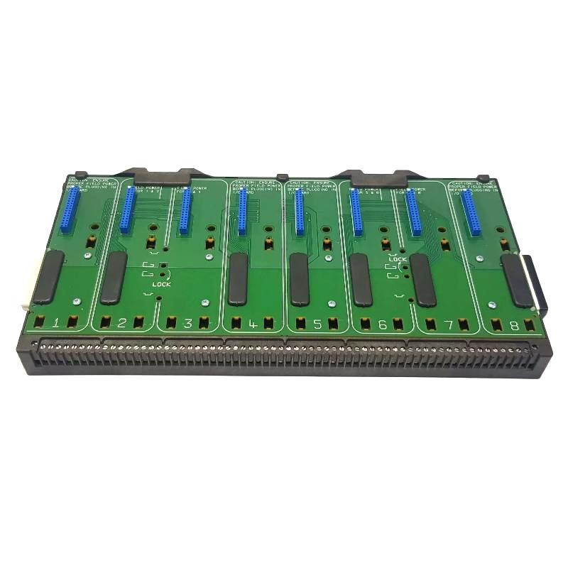
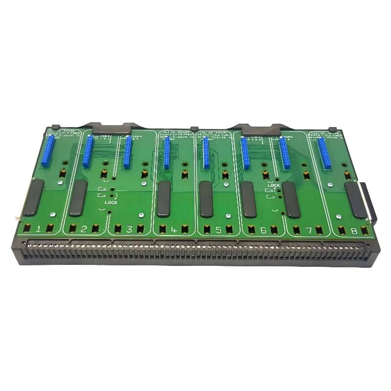
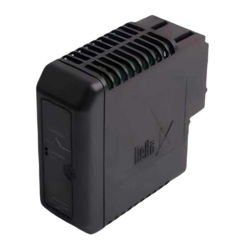
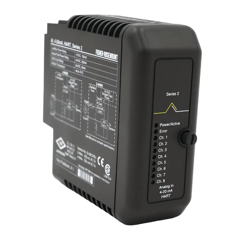
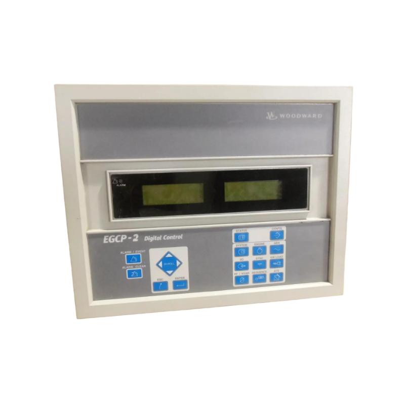
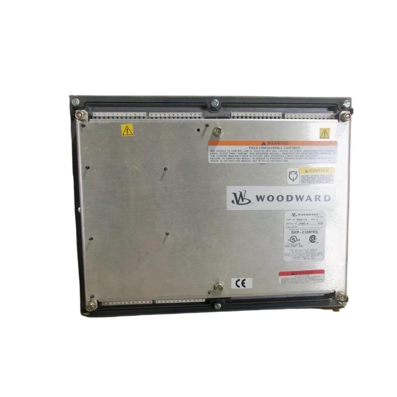
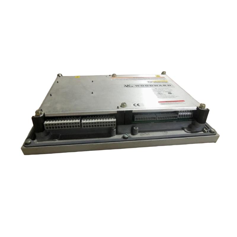
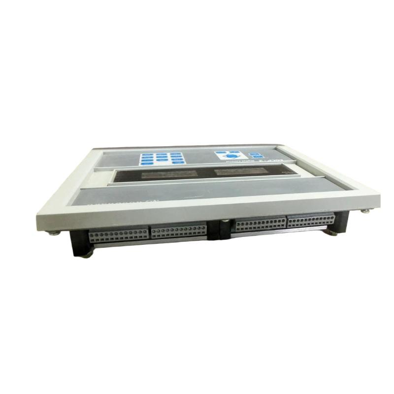
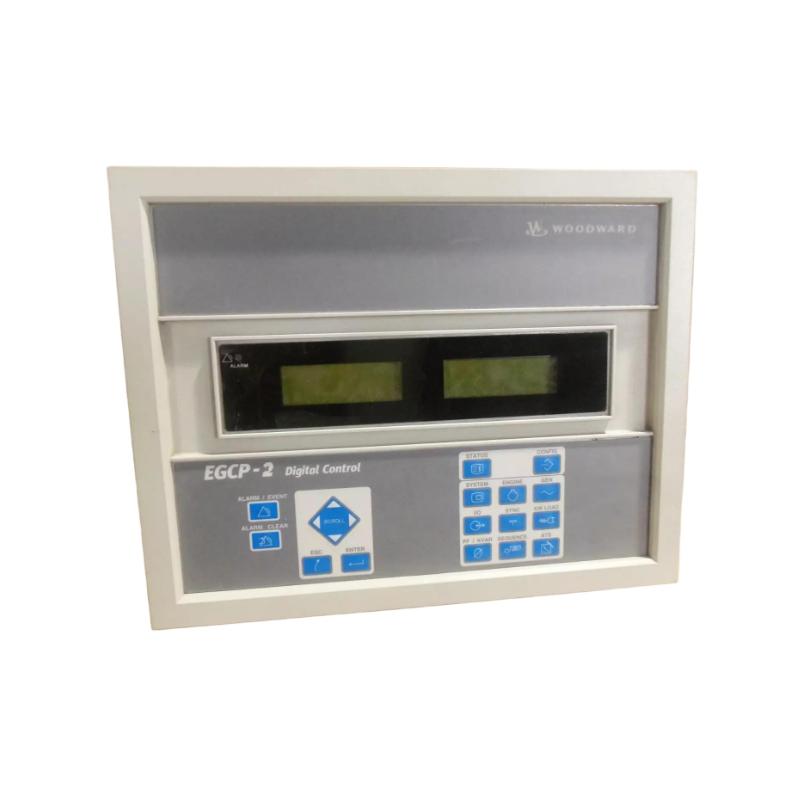
• Woodward 8406-116 Digital Controller
  • Woodward 8406-116 Digital Controller
  • Woodward 8406-116 Digital Controller
  • Woodward 8406-116 Digital Controller
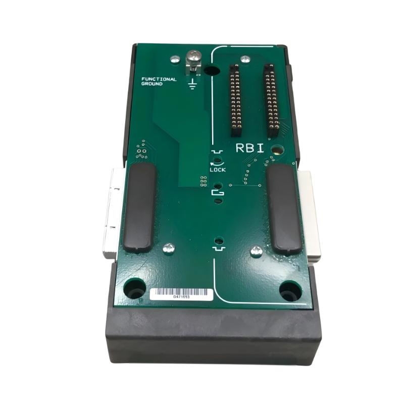
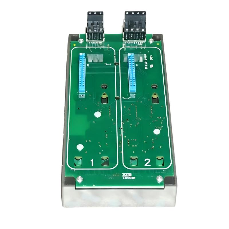
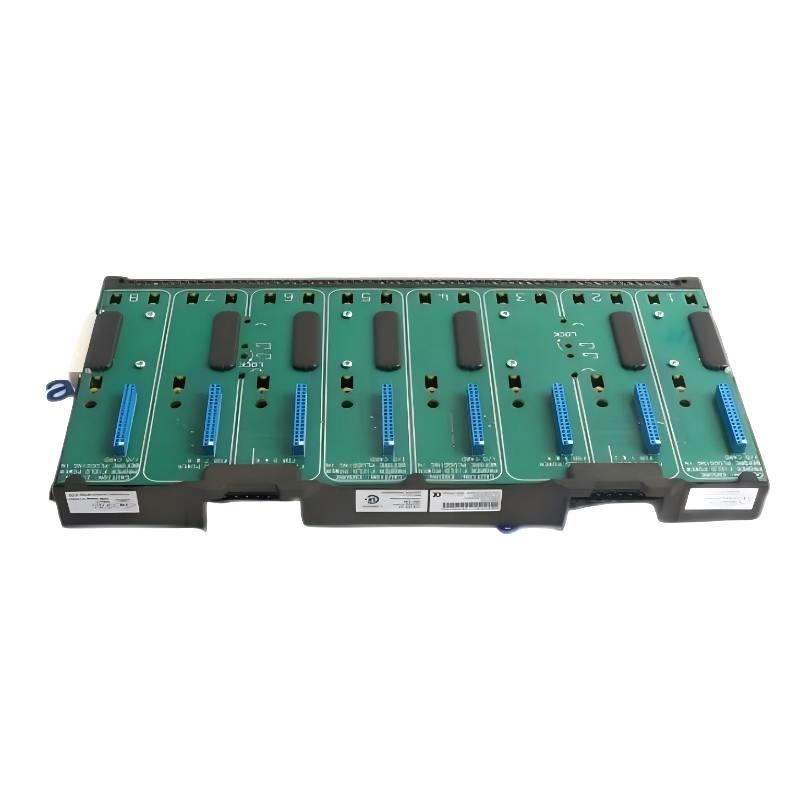
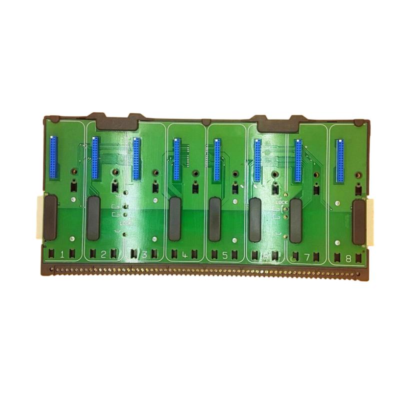
Product Overview The Woodward 8406-116 Digital Controller is an industrial control component designed to process operating signals, execute programmed control logic, and provide control outputs……
Woodward 8406-116 Digital Controller
  • Woodward
  • 8406-116
  • Digital Controller
  • USA
  • 300 x 250 x 100 mm
  • 3.1 kg
  • Xiamen, China
  • New & In Stock
  • T/T, PayPal, Western Union
  • 1 Year
  • 1-3 Working Days
  • DHL, UPS, TNT, FedEx and EMS.
  • 24-Hour Service
  • COO
  • 3

Our advantage

Woodward 8406-116 Digital Controller

Global Logistics

We have a 10-year logistics and express cooperation agreement, so our products can be shipped to any place in the world.

Woodward 8406-116 Digital Controller

Brand new and original

Our products are imported in bulk from the place of origin. Because of the cooperative relationship, our products are all original and 100% new.

Woodward 8406-116 Digital Controller

24-hour service

We provide 7*24 hours service to our customers. We will be there whenever you need us.

Woodward 8406-116 Digital Controller

Price advantage

All our products are priced very favorably because we have our own warehouse and supply.


Company Information
E-mail [email protected]
Mobile +8615980777398
Whatsapp +8615980777398
WeChat 15980777398

Product Overview

The Woodward 8406-116 Digital Controller is an industrial control component designed to process operating signals, execute programmed control logic, and provide control outputs to connected equipment. In a typical engine, turbine, generator, or industrial machinery system, the digital controller acts as the decision-making element between field inputs and physical control devices.

A simplified architecture is:

Sensors → 8406-116 Digital Controller → Actuators / Control Devices → Machine

The controller continuously evaluates available operating information and uses its programmed control strategy to determine the appropriate response.

The supplied physical specifications for the Woodward 8406-116 are 300 × 250 × 100 mm, with a stated weight of 3.1 kg.

Because a digital controller can directly influence machine operation, installation and commissioning should be performed using the approved system documentation and appropriate equipment-isolation procedures.


Technical Specifications

Parameter Details
Manufacturer Woodward
Model 8406-116
Product Type Digital Controller
Main Function Digital Machine Control
Control Role Processing, Logic and Output Control
Application Industrial Engine, Generator and Machinery Systems
Input Function Monitoring and Control Signals
Output Function Control Commands to Connected Equipment
Installation Industrial Control Cabinet / Panel
Dimensions 300 × 250 × 100 mm
Weight 3.1 kg

Function and Working Principle

The 8406-116 operates as the central processing element of a compatible digital control system.

The general control sequence is:

Field Input → Signal Processing → Digital Control Logic → Output Command → Machine Response

The controller can receive information representing machine operating conditions, process those signals using its programmed logic, and generate commands for connected actuators or control equipment.

A typical closed-loop structure is:

Sensor → Digital Controller → Actuator → Engine / Turbine → Sensor

When the operating condition changes, the controller evaluates the new input and determines whether the output needs to be adjusted.

This allows automated control rather than relying on continuous manual intervention.


Role in Industrial Control Systems

A digital controller can perform several functions within an industrial automation system, including:

  • Signal processing
  • Control logic execution
  • Operating-condition monitoring
  • Setpoint management
  • Output command generation
  • Sequence control
  • Alarm handling
  • Interlock processing
  • System coordination

The actual functions of the 8406-116 depend on the complete equipment configuration and application.


Input and Output Architecture

The controller can be viewed as the interface between field devices and controlled machinery.

Input Side

Inputs may originate from compatible:

  • Speed sensors
  • Pressure sensors
  • Temperature sensors
  • Position signals
  • Load measurements
  • Status contacts
  • Control commands

Processing Side

The controller evaluates the available signals according to its programmed control strategy.

Output Side

Outputs can be used to command compatible:

  • Actuators
  • Valves
  • Governors
  • Relays
  • Control interfaces
  • Other machine-control devices

Correct identification of each input and output is essential during installation.


Industrial Applications

The Woodward 8406-116 may be suitable for compatible applications involving:

  • Engine control
  • Generator sets
  • Turbine systems
  • Prime movers
  • Power-generation equipment
  • Mechanical-drive systems
  • Industrial machinery
  • Automated process equipment
  • Rotating machinery
  • Engine monitoring and control

Installation Guide

Step 1 – Verify the Controller

Before installation, confirm:

  • 8406-116
  • Complete model identification
  • System compatibility
  • Power requirements
  • Input configuration
  • Output configuration
  • Communication connections
  • Mounting arrangement

Do not substitute a controller simply because another unit has similar physical dimensions.


Step 2 – Safely Isolate the Equipment

Before replacing or installing the controller:

  1. Shut down the associated machine as required.
  2. Disconnect control power.
  3. Prevent automatic or remote startup.
  4. Isolate relevant energy sources.
  5. Apply lockout/tagout procedures.
  6. Verify the control system is in a safe maintenance condition.

The controller may command actuators directly, so unintended energization can produce machine movement.


Step 3 – Document Existing Wiring

Before removing an existing controller:

  • Photograph all connections.
  • Label each conductor.
  • Record terminal numbers.
  • Identify input circuits.
  • Identify output circuits.
  • Document communication connections.
  • Record grounding connections.
  • Save existing configuration information where applicable.

This documentation is especially important when replacing a controller in an operating plant.


Step 4 – Inspect the Installation Area

The supplied dimensions are:

300 × 250 × 100 mm

The supplied weight is:

3.1 kg

Ensure the cabinet or mounting structure can safely support the controller.

Allow adequate clearance for:

  • Wiring
  • Connectors
  • Ventilation
  • Maintenance
  • Cable routing
  • Removal and replacement

Avoid locations with excessive heat, moisture, contamination, or vibration.


Step 5 – Inspect the Controller

Before installation, inspect the 8406-116 for:

  • Housing damage
  • Cracks
  • Damaged terminals
  • Bent contacts
  • Corrosion
  • Contamination
  • Signs of overheating
  • Mechanical damage

Confirm the model identification before connecting the controller.


Step 6 – Mount the Controller

Secure the controller firmly within the approved mounting location.

Verify:

  • Mounting hardware
  • Panel alignment
  • Mechanical support
  • Cable clearance
  • Connector accessibility
  • Ventilation
  • Vibration resistance

The 3.1 kg supplied weight should be considered when selecting or checking the mounting arrangement.


Step 7 – Connect Power

Verify the correct control-power circuit before applying power.

Check:

  • Power wiring
  • Polarity where applicable
  • Protective devices
  • Terminal tightness
  • Grounding

Do not assume that similar-looking power terminals have identical functions.


Step 8 – Connect Inputs and Outputs

Connect each circuit according to the system wiring documentation.

Separate the circuits logically into:

Field Inputs → Controller → Control Outputs

Verify:

  • Terminal identification
  • Signal type
  • Wiring polarity
  • Cable condition
  • Shielding
  • Grounding
  • Connector seating

Initial Configuration

Before commissioning, confirm that the controller configuration corresponds to the intended application.

Review where applicable:

  • Input assignments
  • Output assignments
  • Setpoints
  • Control parameters
  • Alarm limits
  • Interlocks
  • Communication settings
  • Operating modes

Incorrect configuration can produce symptoms that resemble hardware failure.


Commissioning Procedure

Initial Inspection

Before energizing the controller:

  1. Verify mounting.
  2. Check power wiring.
  3. Check input wiring.
  4. Check output wiring.
  5. Verify grounding.
  6. Inspect connectors.
  7. Confirm configuration.
  8. Ensure the controlled machine is in a safe state.

Power-Up Test

After completing the inspection:

  1. Apply control power.
  2. Observe controller status.
  3. Check diagnostic indications.
  4. Verify communication where applicable.
  5. Confirm expected input status.
  6. Verify that outputs remain in the expected safe condition.

Any unexpected output should be investigated before proceeding.


Input Verification

Verify that the controller receives the expected field signals.

For each critical input:

  • Confirm wiring.
  • Check signal presence.
  • Compare the displayed or measured value with an independent measurement where appropriate.
  • Check for intermittent behavior.
  • Verify scaling or configuration.

An incorrect field signal can cause the controller to make an apparently incorrect control decision.


Output Verification

Under controlled conditions, verify the controller outputs.

Check:

  • Correct output channel
  • Command response
  • Output direction
  • Actuator response
  • Valve movement
  • Governor response
  • Relay operation where applicable

Do not perform uncontrolled output tests on equipment that can start, accelerate, or move unexpectedly.


Controlled Machine Startup

After successful electrical testing:

  1. Start the machine according to the approved operating procedure.
  2. Monitor controller status.
  3. Monitor critical inputs.
  4. Observe actuator outputs.
  5. Verify machine response.
  6. Monitor alarms.
  7. Confirm stable operation.

Perform load changes gradually when appropriate.


Common Failure Symptoms

Symptom Possible Cause
Controller does not power up Power supply or wiring problem
Inputs unavailable Sensor, wiring or input-circuit fault
Outputs inactive Configuration, interlock or controller problem
Unexpected output Incorrect input, configuration or logic condition
Controller resets Unstable power or hardware problem
Communication failure Wiring or communication configuration
Incorrect process response Input, configuration, output or actuator issue
Intermittent operation Loose wiring, vibration or unstable supply
Excessive alarms Field signal, configuration or system problem

Troubleshooting Guide

Controller Does Not Power Up

Check:

  1. Control-power source.
  2. Protective devices.
  3. Power wiring.
  4. Terminal connections.
  5. Grounding.
  6. Controller condition.

Always verify the external power supply before diagnosing an internal controller fault.


Controller Powers Up but Inputs Are Missing

Inspect:

  • Sensor wiring
  • Input terminals
  • Field devices
  • Signal continuity
  • Signal quality
  • Input configuration
  • Grounding and shielding

If several unrelated inputs fail simultaneously, investigate the shared power or wiring path first.


Controller Output Is Not Active

Possible causes include:

  • Missing input condition
  • Interlock
  • Permissive not satisfied
  • Incorrect operating mode
  • Incorrect configuration
  • Controller logic condition
  • Output-circuit fault

Trace the control logic from the input condition through the expected output.


Unexpected Output

If an output activates unexpectedly:

  1. Verify the input conditions.
  2. Check operating mode.
  3. Review interlocks.
  4. Verify configuration.
  5. Inspect wiring.
  6. Check whether the output is actually coming from the controller.

Unexpected output behavior should be treated carefully when connected equipment can move or change operating conditions.


Controller Resets

Repeated resets can result from:

  • Unstable power
  • Loose terminals
  • Electrical interference
  • Wiring problems
  • Excessive environmental temperature
  • Internal hardware problems

Monitor the controller’s power supply during the event where appropriate.

If the power supply remains stable while the controller repeatedly resets, investigate the controller and surrounding electrical environment.


Communication Failure

If the controller cannot communicate with another device, inspect:

  • Communication cables
  • Connectors
  • Grounding
  • Shielding
  • Network configuration
  • Communication settings
  • External communication equipment

Do not replace the controller until the communication path has been checked.


Incorrect Control Response

When the machine does not respond as expected, use the following diagnostic chain:

Sensor → Input → Controller Logic → Output → Actuator → Machine

Check each stage separately.

For example, if the controller receives an incorrect speed signal, it may generate a correct output based on incorrect information. In this situation, replacing the controller would not solve the underlying problem.


Preventive Maintenance

Recommended maintenance includes:

  • Visual inspection
  • Terminal inspection
  • Connector inspection
  • Power-supply verification
  • Grounding checks
  • Signal-wiring inspection
  • Communication inspection
  • Cooling and ventilation inspection
  • Alarm-history review
  • Mounting-hardware inspection
  • Vibration inspection

Avoid unnecessary changes to controller parameters during routine maintenance.


Environmental Considerations

Temperature

Excessive temperature can affect electronic controller reliability. Ensure the installation location has suitable thermal conditions.

Vibration

Engine and turbine installations can expose control equipment to continuous vibration. Check mounting hardware regularly.

Moisture

Protect the controller from condensation, water, and excessive humidity.

Dust and Oil

Industrial contamination can affect connectors, terminals, and cooling paths.

Electrical Interference

Route low-level signal and communication wiring appropriately to reduce exposure to high-energy electrical sources.


System Integration

The Woodward 8406-116 should be considered part of the complete machine-control architecture.

Component Typical Function
Speed Sensor Measures rotational speed
Pressure Sensor Measures system pressure
Temperature Sensor Measures thermal condition
Other Field Inputs Provide operating information
8406-116 Processes inputs and executes control logic
Actuator Converts command into physical movement
Valve / Governor Controls machine operation
Engine / Turbine Produces mechanical power
Generator / Load Uses mechanical output
Protection System Provides abnormal-condition protection
Operator Interface Provides human-machine interaction

A fault in any of these components can influence the controller’s observed behavior.


Controller Replacement Procedure

Before removing the existing controller, record:

  • Model number
  • Terminal assignments
  • Input wiring
  • Output wiring
  • Communication wiring
  • Power connections
  • Grounding
  • Configuration
  • Setpoints
  • Active alarms

After installation:

  1. Verify mounting.
  2. Confirm all wiring.
  3. Apply control power.
  4. Verify controller status.
  5. Check inputs.
  6. Check outputs.
  7. Verify communication.
  8. Perform controlled startup.
  9. Confirm stable machine operation.

Key Advantages

  • Designed for digital industrial control
  • Provides centralized processing of control signals
  • Supports automated control logic
  • Interfaces field inputs with control outputs
  • Suitable for compatible engine and turbine applications
  • Can support generator and mechanical-drive systems
  • Supplied dimensions of 300 × 250 × 100 mm
  • Supplied weight of 3.1 kg
  • Suitable for integration into industrial control architectures

Technical FAQs

What is the Woodward 8406-116?

The Woodward 8406-116 is a Digital Controller designed to process control signals and execute digital control functions within compatible industrial systems.

What is the role of a digital controller?

It receives operating information, processes the inputs according to programmed logic, and generates control outputs for connected equipment.

What equipment can a digital controller interact with?

Depending on the system configuration, it can interact with sensors, actuators, valves, governors, relays, operator interfaces, and other control equipment.

What are the dimensions?

The supplied dimensions are 300 × 250 × 100 mm.

What is the weight?

The supplied weight is 3.1 kg.

Why should the input signals be checked before replacing the controller?

An incorrect sensor signal or damaged input circuit can cause incorrect controller outputs even when the controller hardware is operating normally.

What should be checked if the controller does not power up?

Check the external control-power supply, protective devices, wiring, terminals, grounding, and connectors before diagnosing an internal controller fault.

What can cause repeated controller resets?

Possible causes include unstable power, loose connections, electrical interference, environmental conditions, or internal hardware problems.

What should be checked if an output does not activate?

Check the relevant input condition, operating mode, interlocks, permissives, configuration, output wiring, and connected actuator.

What should be verified after controller replacement?

Power-up, configuration, input signals, output signals, communication, interlocks, alarms, actuator response, and controlled machine operation should all be verified.


Conclusion

The Woodward 8406-116 Digital Controller serves as the central processing element of a compatible industrial control system. It receives field information, executes programmed control logic, and generates commands for connected actuators and other control devices.

Successful installation requires careful attention to power, signal wiring, grounding, configuration, mounting, communication, and output verification. During commissioning, the controller should be tested progressively—from power-up and individual inputs through controlled outputs and finally to machine operation.

When troubleshooting, the most effective approach is to follow the complete control chain:

Field Signal → Controller Input → Digital Logic → Controller Output → Actuator → Machine Response

This prevents sensor, wiring, configuration, actuator, and mechanical faults from being incorrectly attributed to the controller itself.

With supplied dimensions of 300 × 250 × 100 mm and a weight of 3.1 kg, the 8406-116 is a substantial industrial digital-control component intended for integration into compatible engine, generator, turbine, and machinery-control systems.


Related Products

Get the latest price? We will reply as soon as possible (within 12 hours)

No:77501