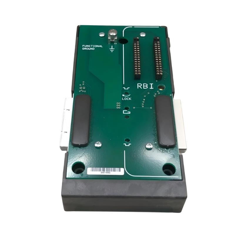
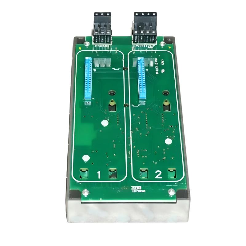
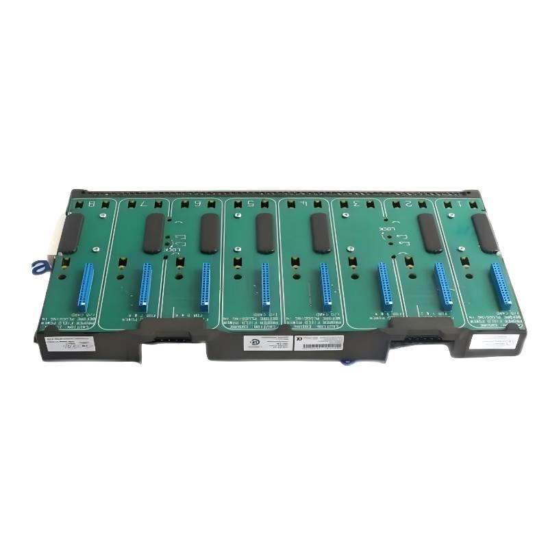
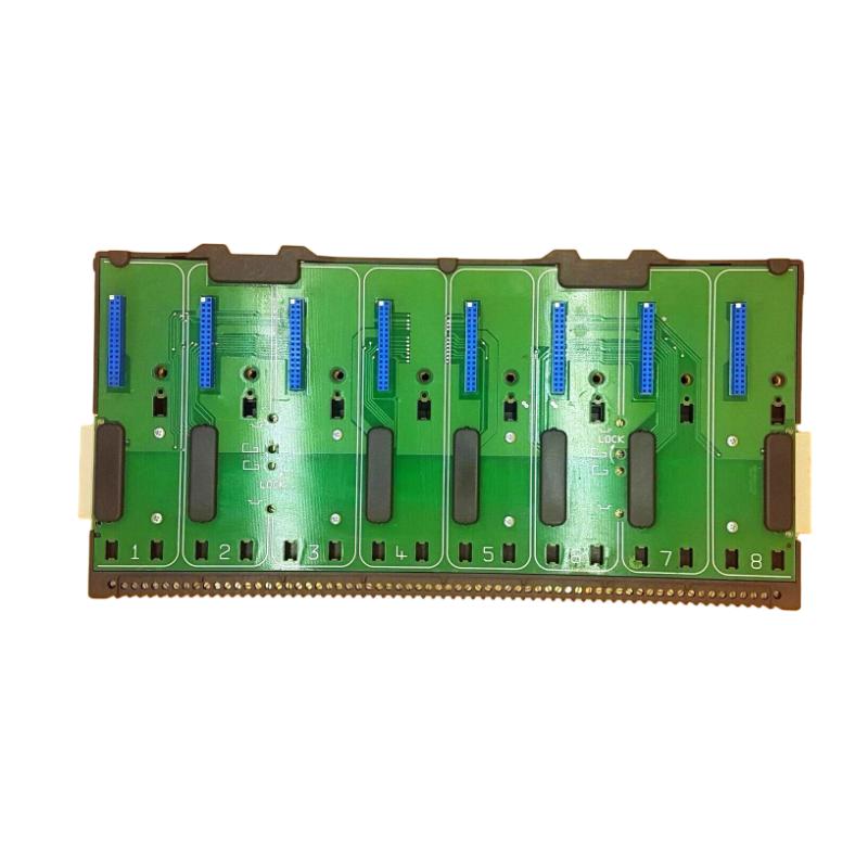
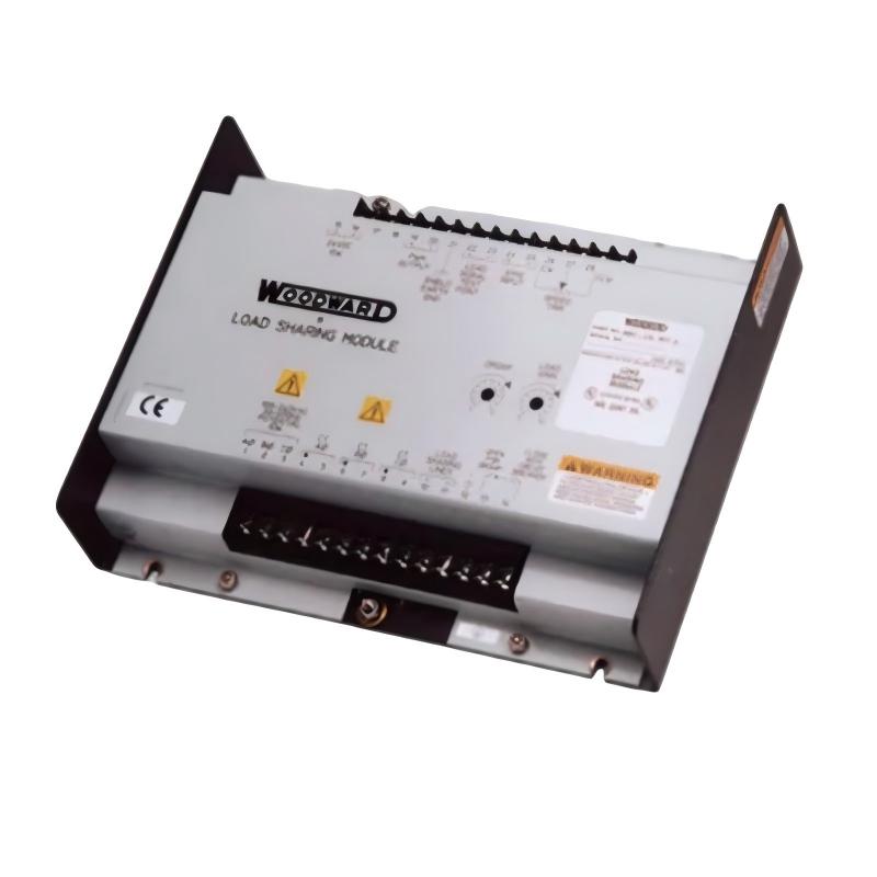
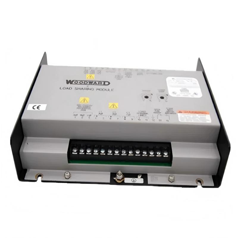
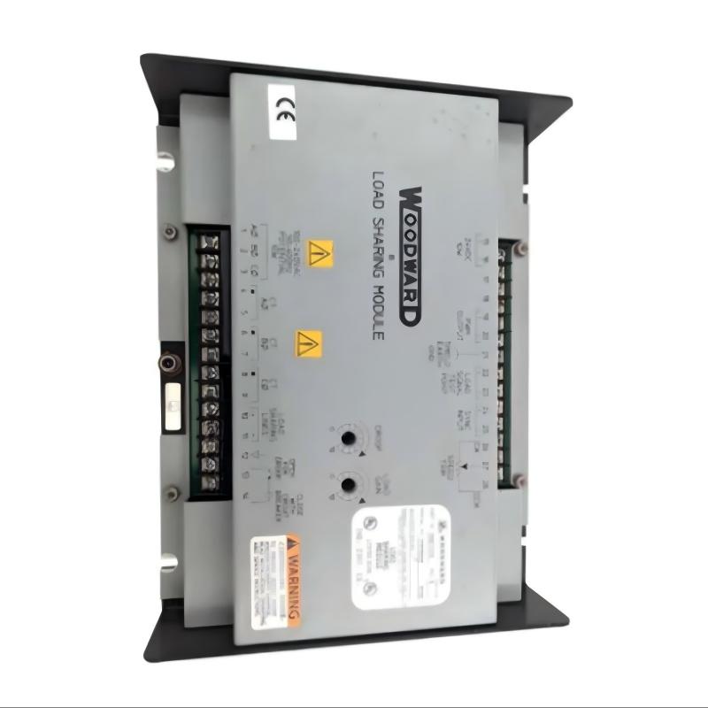
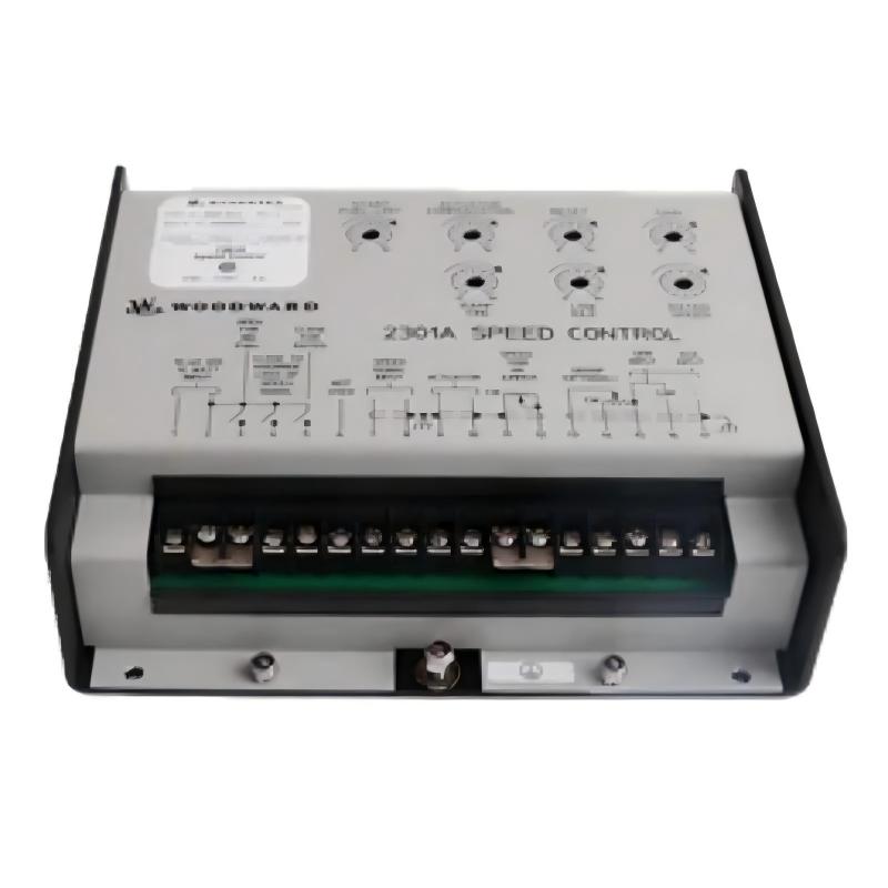
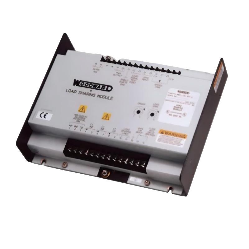
• Woodward 8405-809 Electric Valve Actuator
  • Woodward 8405-809 Electric Valve Actuator
  • Woodward 8405-809 Electric Valve Actuator
  • Woodward 8405-809 Electric Valve Actuator
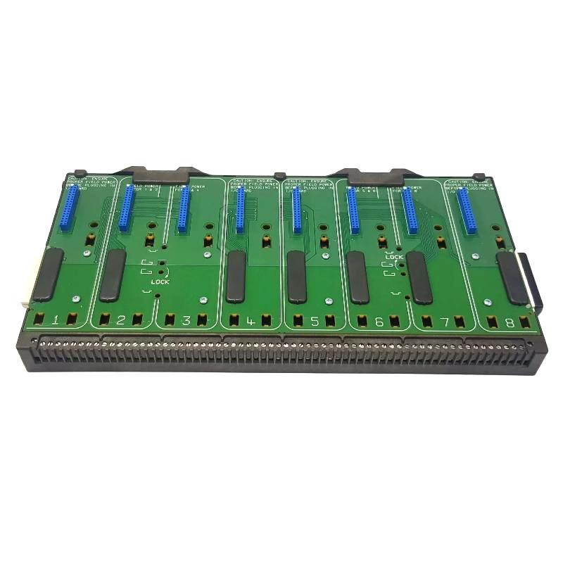
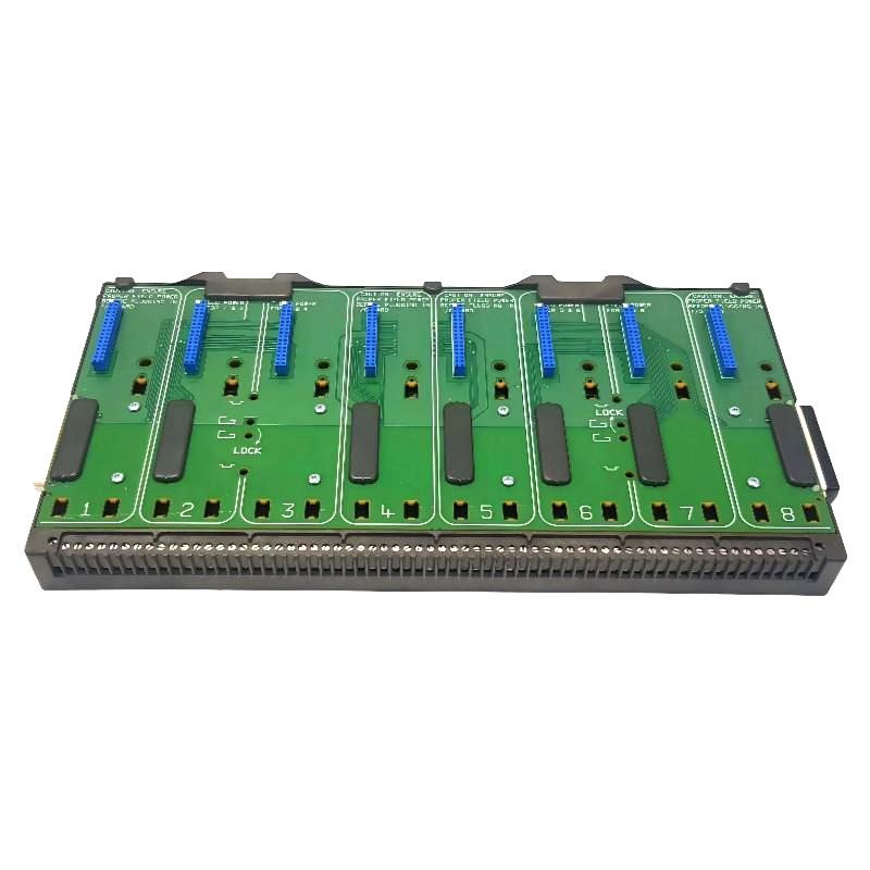
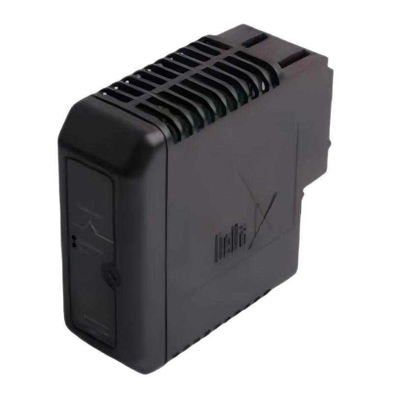
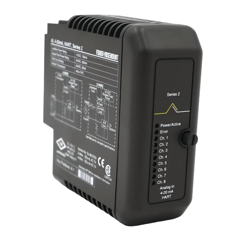
Product Overview The Woodward 8405-809 Electric Valve Actuator is an industrial electromechanical component designed to provide controlled positioning of a valve or valve-linked mechanism. In a……
Woodward 8405-809 Electric Valve Actuator
  • Woodward
  • 8405-809
  • Electric Valve Actuator
  • USA
  • 200 × 25 × 120 mm
  • 1.5 kg
  • Xiamen, China
  • New & In Stock
  • T/T, PayPal, Western Union
  • 1 Year
  • 1-3 Working Days
  • DHL, UPS, TNT, FedEx and EMS.
  • 24-Hour Service
  • COO
  • 2

Our advantage

Woodward 8405-809 Electric Valve Actuator

Global Logistics

We have a 10-year logistics and express cooperation agreement, so our products can be shipped to any place in the world.

Woodward 8405-809 Electric Valve Actuator

Brand new and original

Our products are imported in bulk from the place of origin. Because of the cooperative relationship, our products are all original and 100% new.

Woodward 8405-809 Electric Valve Actuator

24-hour service

We provide 7*24 hours service to our customers. We will be there whenever you need us.

Woodward 8405-809 Electric Valve Actuator

Price advantage

All our products are priced very favorably because we have our own warehouse and supply.


Company Information
E-mail [email protected]
Mobile +8615980777398
Whatsapp +8615980777398
WeChat 15980777398

Product Overview

The Woodward 8405-809 Electric Valve Actuator is an industrial electromechanical component designed to provide controlled positioning of a valve or valve-linked mechanism. In an automated control system, the actuator converts an electrical command from the controller into mechanical movement, allowing the connected valve to move toward the required operating position.

Valve actuation is important in systems where controlled flow of fuel, steam, gas, air, or another process medium is required. The actuator therefore forms an important interface between electronic control equipment and physical process equipment.

The supplied physical specifications for the Woodward 8405-809 are 200 × 25 × 120 mm, with a stated weight of 1.5 kg.

Because valve movement can directly affect process flow and machine operation, installation should include careful verification of mechanical travel, actuator direction, electrical connections, and valve position.


Technical Specifications

Parameter Details
Manufacturer Woodward
Model 8405-809
Product Type Electric Valve Actuator
Main Function Electrically Controlled Valve Positioning
Actuation Type Electric
Control Role Valve Position Control
Application Industrial Control and Process Equipment
Typical Installation Valve / Actuation Assembly
Dimensions 200 × 25 × 120 mm
Weight 1.5 kg

Function and Working Principle

The 8405-809 operates as the final mechanical element of a valve-control loop.

A simplified system can be represented as:

Controller → Electrical Command → 8405-809 → Valve Movement → Process Flow → Feedback

The controller determines the desired valve position based on process conditions. The actuator receives the corresponding command and produces mechanical movement.

A typical sequence is:

  1. The control system determines the required valve position.
  2. An electrical command is transmitted to the actuator.
  3. The actuator drive responds to the command.
  4. Mechanical movement is transferred to the valve.
  5. The valve changes position.
  6. Process flow changes accordingly.
  7. Feedback or process measurements allow the controller to make further corrections.

This arrangement provides automatic valve positioning without requiring continuous manual adjustment.


Role in Industrial Control Systems

An electric valve actuator can play a critical role in automated process and machinery control.

It may participate in:

  • Flow regulation
  • Fuel control
  • Steam control
  • Gas control
  • Air control
  • Engine control
  • Turbine control
  • Generator auxiliary systems
  • Automated process sequencing

The exact function depends on the valve assembly and control system in which the 8405-809 is installed.


Valve Position Control

A typical closed-loop valve-control system is:

Process Sensor → Controller → 8405-809 → Valve → Process → Sensor

For example, when the control system detects that more flow is required, it can command the actuator to move the valve toward a more open position.

Conversely:

Reduced Flow Requirement → Reduced Valve Opening → Lower Process Flow

The actuator therefore allows the controller to translate an electronic decision into physical process control.


Industrial Applications

The Woodward 8405-809 may be suitable for compatible applications involving:

  • Engine systems
  • Turbine systems
  • Generator systems
  • Fuel-control assemblies
  • Steam systems
  • Gas-control systems
  • Air-control systems
  • Industrial process equipment
  • Automated valve systems
  • Mechanical control assemblies

Installation Guide

Step 1 – Verify the Actuator

Before installation, confirm:

  • 8405-809
  • Complete model identification
  • Valve compatibility
  • Mechanical mounting arrangement
  • Electrical interface
  • Required travel
  • Valve operating direction
  • Control-system compatibility

A similar-looking actuator should not be installed without confirming mechanical and electrical compatibility.


Step 2 – Isolate the System

Before removing or installing the actuator:

  1. Shut down the associated equipment.
  2. Disconnect applicable electrical power.
  3. Prevent automatic or remote operation.
  4. Isolate the controlled process where necessary.
  5. Depressurize the valve system when applicable.
  6. Follow lockout/tagout procedures.
  7. Verify that the valve and actuator can be safely serviced.

For fuel, steam, gas, or pressurized systems, proper process isolation is especially important.


Step 3 – Record the Existing Installation

Before removing the existing actuator:

  • Photograph the assembly.
  • Record mounting orientation.
  • Label electrical conductors.
  • Record terminal assignments.
  • Mark the valve position.
  • Record linkage geometry.
  • Note mechanical stops.
  • Record existing control settings.

This information helps prevent incorrect reassembly.


Step 4 – Inspect the Valve

The actuator should not be installed onto a defective or seized valve.

Inspect the valve for:

  • Mechanical binding
  • Excessive friction
  • Corrosion
  • Damaged shaft
  • Worn linkage
  • Contamination
  • Abnormal travel resistance
  • Damaged mounting points

A mechanically defective valve can overload the actuator.


Step 5 – Inspect the Replacement Actuator

Inspect the Woodward 8405-809 for:

  • Damaged housing
  • Damaged terminals
  • Bent contacts
  • Corrosion
  • Contamination
  • Signs of overheating
  • Mechanical damage

Verify the model marking before installation.


Step 6 – Mount the Actuator

The supplied dimensions are:

200 × 25 × 120 mm

The supplied weight is:

1.5 kg

The actuator should be mounted securely with adequate mechanical support.

Check:

  • Mounting alignment
  • Fastener security
  • Shaft or linkage alignment
  • Mechanical clearance
  • Valve travel
  • Access for maintenance

Step 7 – Connect the Mechanical Interface

Connect the actuator to the valve according to the equipment design.

Verify:

  • Correct attachment point
  • Correct valve direction
  • Neutral position
  • Full-open position
  • Full-closed position
  • Mechanical stops
  • Linkage clearance

The actuator should not be forced against the valve’s mechanical stops during normal operation.


Step 8 – Connect Electrical Wiring

Check:

  • Power connections
  • Command connections
  • Signal polarity where applicable
  • Grounding
  • Shielding
  • Connector seating
  • Terminal tightness

Do not energize the actuator until all connections have been inspected.


Commissioning Procedure

Mechanical Inspection

Before applying the control command:

  • Confirm secure mounting.
  • Check valve movement.
  • Verify linkage alignment.
  • Confirm travel range.
  • Inspect mechanical stops.
  • Make sure there is no binding.

Electrical Verification

Check:

  1. Control power.
  2. Wiring continuity where appropriate.
  3. Command signal.
  4. Grounding.
  5. Connector condition.
  6. Control-system configuration.

Controlled Valve Movement Test

Under safe conditions:

  1. Apply the appropriate control command.
  2. Observe actuator movement.
  3. Confirm the valve moves in the correct direction.
  4. Check for smooth movement.
  5. Verify partial positions.
  6. Confirm full travel.
  7. Return the valve to its required operating position.

If the valve moves in the wrong direction, stop the test and investigate before continuing.


Process Commissioning

After actuator movement has been verified:

  1. Place the associated system in the approved startup condition.
  2. Start the equipment.
  3. Monitor valve position.
  4. Monitor process pressure, flow, or other relevant variables.
  5. Observe actuator response.
  6. Perform controlled process changes.
  7. Verify that valve movement corresponds to control commands.

Common Failure Symptoms

Symptom Possible Cause
Valve does not move Power, command, actuator or valve problem
Valve moves in wrong direction Wiring or mechanical configuration
Valve moves slowly Mechanical friction or excessive load
Valve movement is unstable Command or mechanical problem
Full valve travel unavailable Mechanical stop or linkage problem
Actuator overheats Excessive load or binding
Valve position is inaccurate Calibration or linkage issue
Intermittent movement Loose wiring or unstable supply
Valve remains fixed Mechanical seizure or missing command

Troubleshooting Guide

Valve Does Not Move

Check:

  1. Actuator power.
  2. Control command.
  3. Electrical wiring.
  4. Connectors.
  5. Mechanical linkage.
  6. Valve condition.
  7. Actuator condition.

First determine whether the actuator is receiving the correct command.


Actuator Has Power but Valve Does Not Move

If electrical power is present but there is no mechanical movement:

  • Inspect the actuator drive.
  • Check the mechanical connection.
  • Check valve shaft movement.
  • Look for mechanical binding.
  • Inspect linkage.
  • Verify that the valve is not seized.

A powered actuator does not necessarily indicate that the mechanical system is free to move.


Valve Moves in the Wrong Direction

Possible causes include:

  • Incorrect wiring
  • Incorrect command configuration
  • Reversed mechanical linkage
  • Incorrect actuator mounting
  • Incorrect valve orientation

Verify direction before returning the system to automatic operation.


Valve Moves Slowly

Possible causes include:

  • Excessive valve friction
  • Mechanical binding
  • Corrosion
  • Excessive process force
  • Actuator overload
  • Electrical supply problem
  • Internal actuator wear

Inspect the valve and linkage before replacing the actuator.


Valve Does Not Reach Full Open or Full Closed Position

Check:

  • Mechanical stops
  • Linkage geometry
  • Valve travel
  • Actuator mounting
  • Obstructions
  • Mechanical wear
  • Control configuration

Incorrect linkage adjustment can prevent the actuator from achieving the required valve position.


Actuator Overheats

Investigate:

  • Valve friction
  • Continuous mechanical load
  • Incorrect mounting
  • Mechanical obstruction
  • Excessive process force
  • Electrical problems
  • Environmental temperature

An actuator that continuously works against excessive mechanical resistance may overheat even when its electrical circuit is functioning normally.


Valve Position Is Unstable

Possible causes include:

  • Unstable command signal
  • Electrical interference
  • Loose connections
  • Mechanical backlash
  • Valve friction
  • Control-loop instability
  • Actuator wear

Check the stability of the control command before making mechanical adjustments.


Mechanical Valve Inspection

The valve and actuator should be evaluated together.

Inspect:

  • Valve shaft
  • Linkage
  • Couplings
  • Bearings or joints
  • Mechanical stops
  • Mounting brackets
  • Valve body
  • Signs of corrosion
  • Excessive friction

If the valve cannot move smoothly under safe isolated conditions, correcting the mechanical problem should take priority.


Control Signal Verification

When troubleshooting, trace the control path:

Controller Output → Wiring → 8405-809 Input → Actuator Movement → Valve Movement

This helps separate electronic, electrical, and mechanical faults.

If the controller produces the correct command but the actuator does not respond, investigate the actuator and its connections.

If the actuator follows the command but the valve does not move correctly, investigate the mechanical interface.


Preventive Maintenance

Recommended maintenance activities include:

  • Visual inspection
  • Mounting inspection
  • Fastener checks
  • Valve linkage inspection
  • Electrical terminal inspection
  • Connector inspection
  • Grounding checks
  • Valve travel verification
  • Actuator response testing
  • Operating-temperature monitoring
  • Vibration inspection

Periodic valve inspection is particularly important because increasing mechanical resistance can gradually overload the actuator.


Environmental Considerations

The actuator should be installed in an appropriate industrial environment.

Temperature

Excessive ambient or process-related heat can affect actuator performance.

Vibration

Engine and turbine installations can expose the actuator to continuous vibration. Mounting hardware should remain secure.

Moisture

Moisture can contribute to corrosion and electrical problems.

Oil and Dust

Contamination can affect mechanical movement, connectors, and electrical terminals.

Process Conditions

If the actuator controls fuel, steam, gas, or another hazardous or pressurized medium, the surrounding process conditions must be considered during maintenance and commissioning.


System Integration

The 8405-809 typically functions within a larger control architecture.

Component Typical Function
Process Sensor Measures process condition
Controller Determines required valve position
Control Wiring Transfers command
8405-809 Produces mechanical valve movement
Valve Linkage Transfers actuator motion
Control Valve Regulates process flow
Process Equipment Uses the controlled medium
Feedback System Reports resulting condition

A fault anywhere in this chain can produce valve-control symptoms.


Replacement Considerations

Before replacing the Woodward 8405-809, record:

  • Complete model number
  • Valve position
  • Mounting orientation
  • Linkage geometry
  • Electrical wiring
  • Terminal assignments
  • Control configuration
  • Existing fault symptoms
  • Mechanical travel limits

After replacement, verify:

  1. Mounting
  2. Valve alignment
  3. Electrical connections
  4. Direction of movement
  5. Full valve travel
  6. Partial positioning
  7. Control response
  8. Process response

Key Advantages

  • Designed for electric valve actuation
  • Converts electrical commands into controlled mechanical movement
  • Suitable for industrial valve-control applications
  • Can support engine and turbine systems
  • Suitable for generator and process-control environments
  • Compact 200 × 25 × 120 mm form factor
  • Supplied weight of 1.5 kg
  • Suitable for automated valve-positioning applications

Technical FAQs

What is the Woodward 8405-809?

The Woodward 8405-809 is an Electric Valve Actuator designed to convert electrical control commands into mechanical valve movement.

What is the main purpose of an electric valve actuator?

It allows an electronic control system to automatically position a valve according to operating requirements.

What types of equipment can use a valve actuator?

Depending on system design, applications can include engines, turbines, generators, fuel systems, steam systems, gas systems, and industrial process equipment.

What are the dimensions?

The supplied dimensions are 200 × 25 × 120 mm.

What is the weight?

The supplied weight is 1.5 kg.

Why is valve condition important when troubleshooting an actuator?

A seized, contaminated, or high-friction valve can overload the actuator and produce symptoms that resemble an actuator failure.

What should be checked if the valve moves in the wrong direction?

Check electrical wiring, command configuration, actuator mounting, linkage orientation, and valve configuration.

Why might the actuator overheat?

Excessive mechanical resistance, continuous loading, incorrect installation, electrical problems, or unsuitable environmental conditions can contribute to overheating.

Should the actuator be replaced immediately if the valve does not move?

No. Check the control command, power supply, wiring, actuator connection, linkage, and valve condition before replacing the actuator.

What should be verified after installing a replacement?

Verify mounting, mechanical alignment, valve direction, travel range, electrical command, actuator response, and controlled process operation.


Conclusion

The Woodward 8405-809 Electric Valve Actuator provides the electromechanical interface between an automated control system and a physical valve. Its primary role is to transform an electrical command into controlled mechanical movement, allowing compatible equipment to regulate fuel, steam, gas, air, or other process flows.

Reliable installation requires careful attention to electrical connections, valve condition, linkage geometry, mechanical travel, actuator direction, and process isolation. Troubleshooting should follow the complete path from the controller through the actuator to the valve rather than assuming that every positioning problem originates inside the actuator.

With supplied dimensions of 200 × 25 × 120 mm and a weight of 1.5 kg, the 8405-809 is a compact industrial valve-actuation component for compatible engine, turbine, generator, and process-control systems.


Related Products

Get the latest price? We will reply as soon as possible (within 12 hours)

No:77501