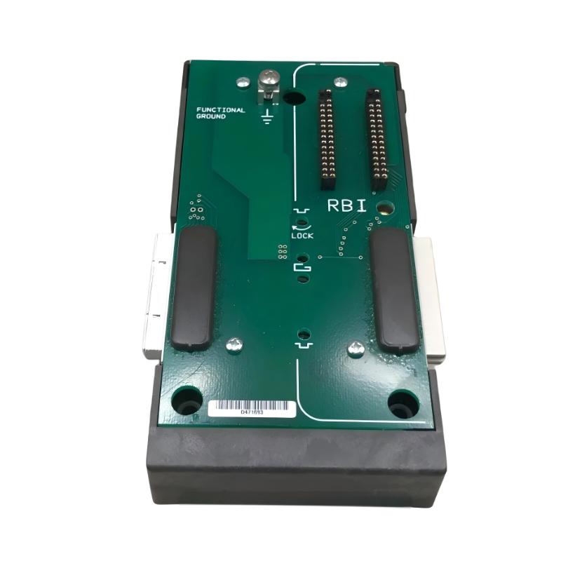
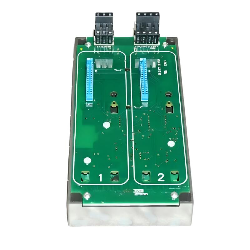
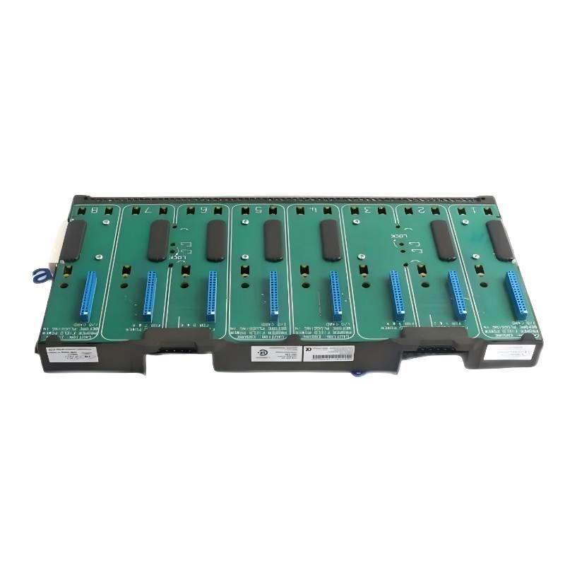
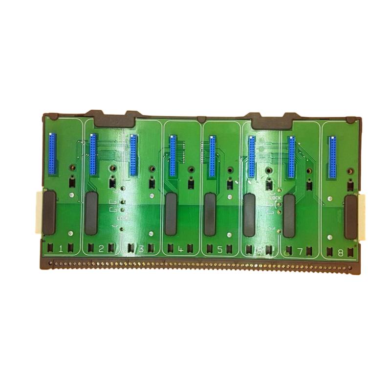
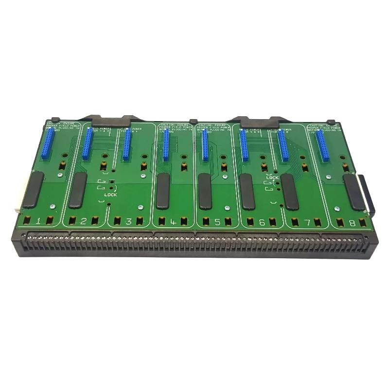
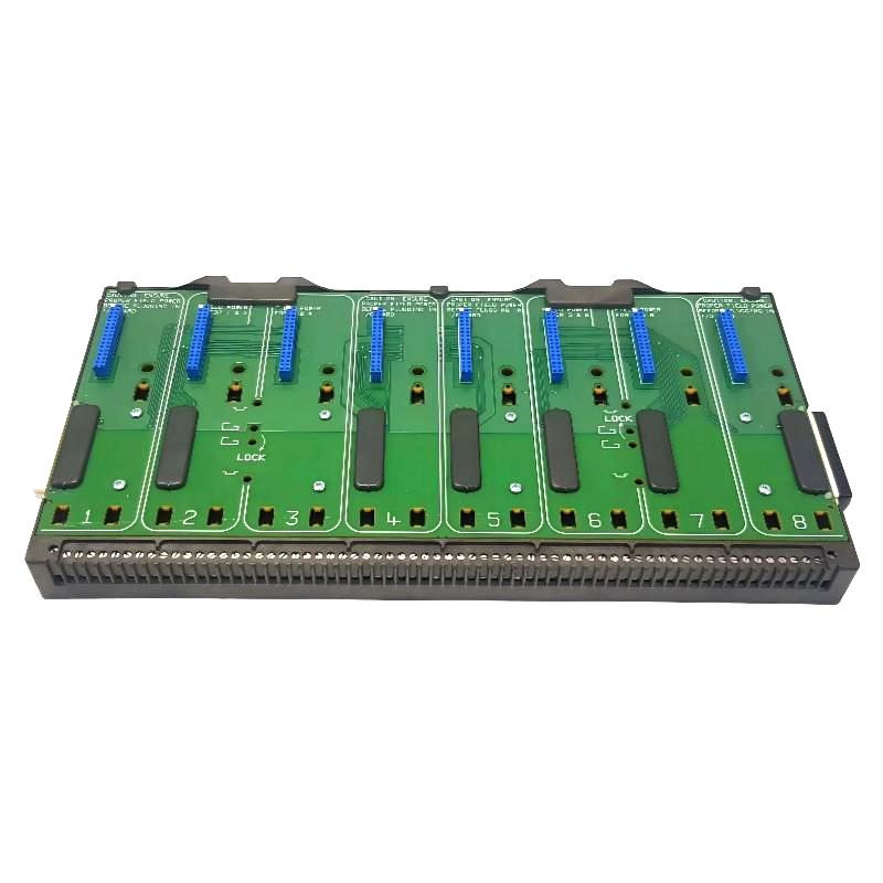
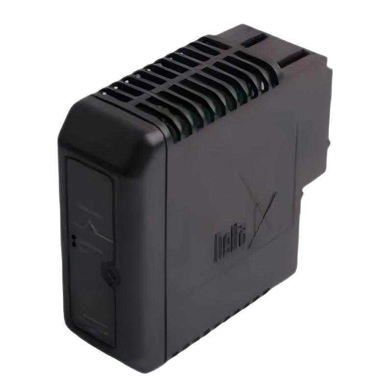
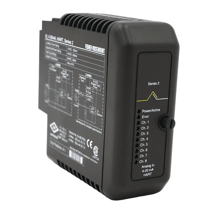
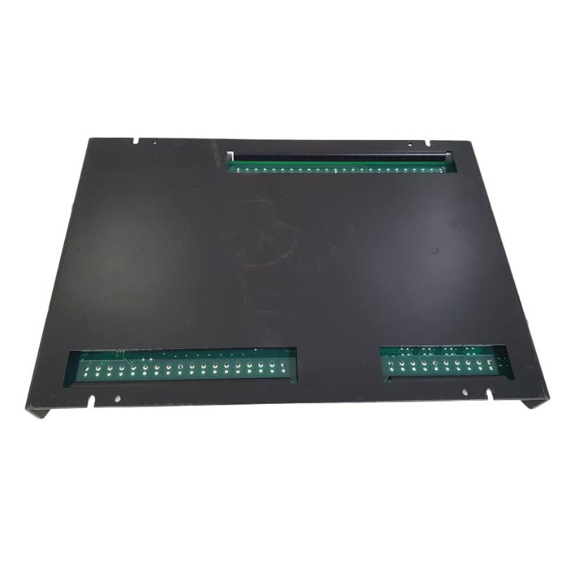
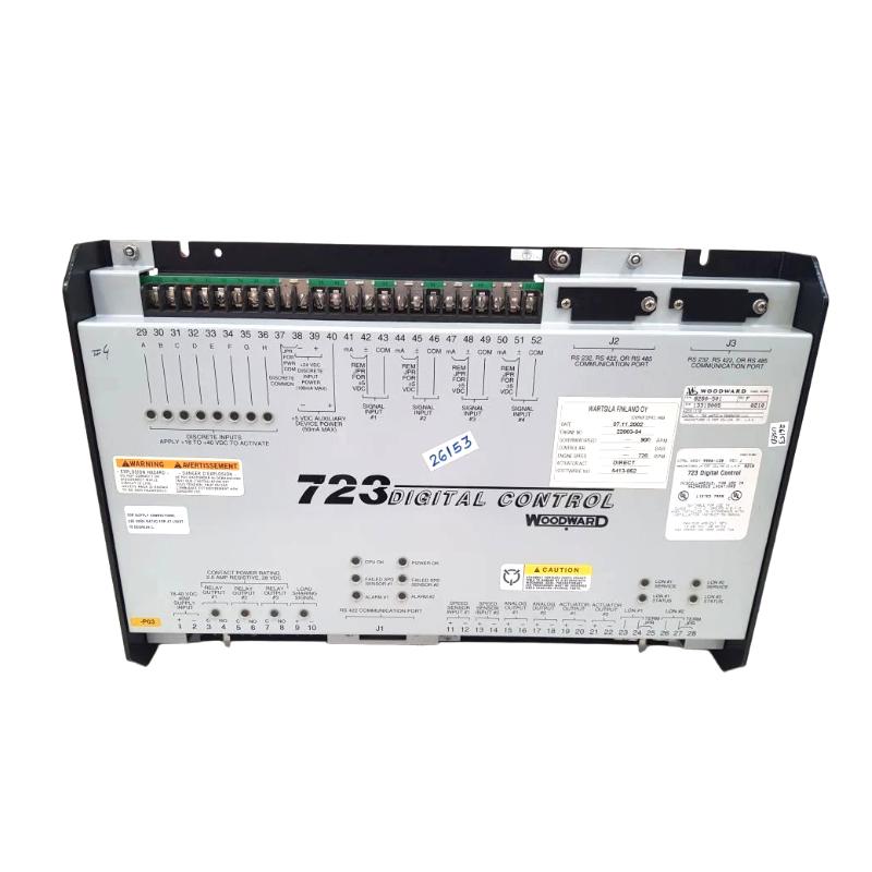
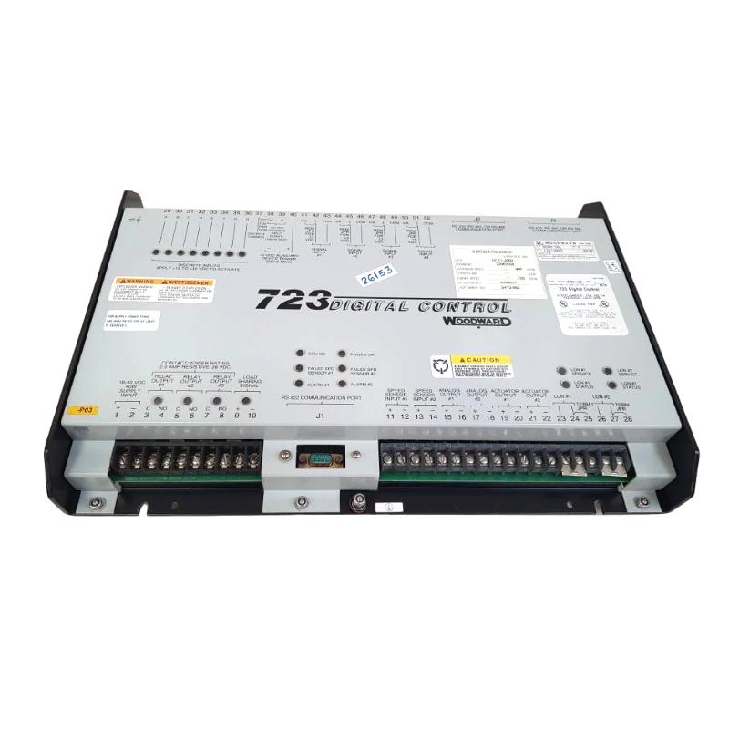
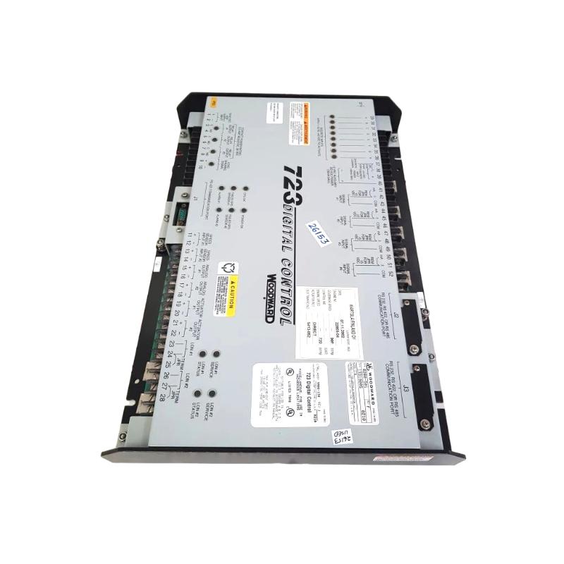
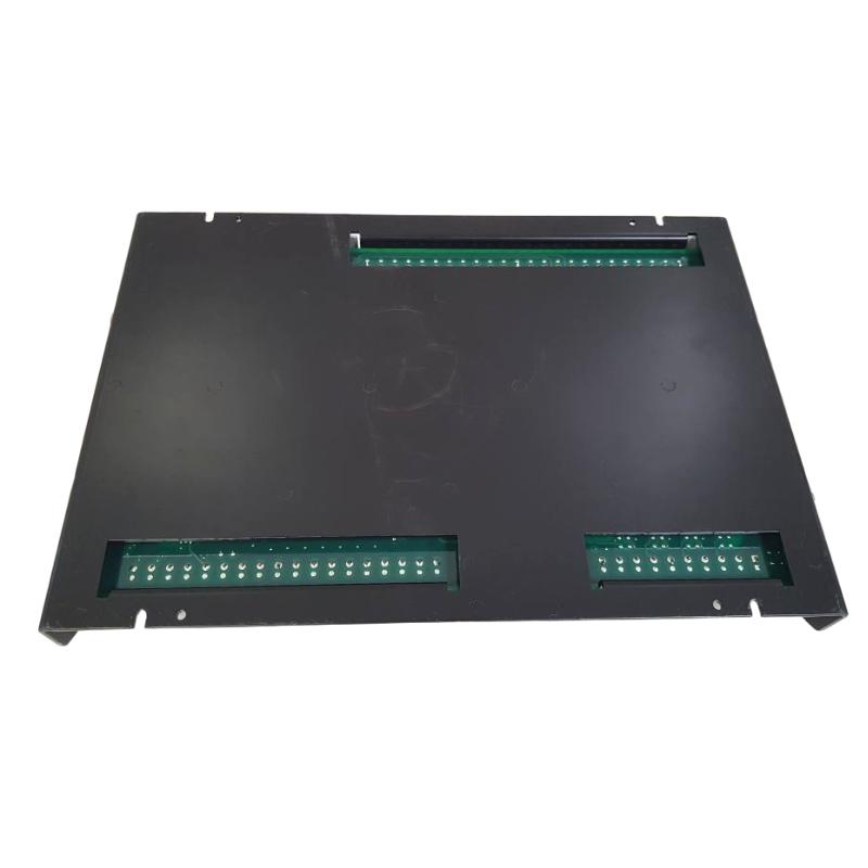
• Woodward 8280-501 Digital Control Module
  • Woodward 8280-501 Digital Control Module
  • Woodward 8280-501 Digital Control Module
  • Woodward 8280-501 Digital Control Module
Product Overview The Woodward 8280-501 Digital Control Module is an industrial control component designed to provide digital processing and control functions within compatible Woodward engine, ……
Woodward 8280-501 Digital Control Module
  • Woodward
  • 8280-501
  • Digital Control Module
  • USA
  • 50 x 150 x 120 mm
  • 1.81 kg
  • Xiamen, China
  • New & In Stock
  • T/T, PayPal, Western Union
  • 1 Year
  • 1-3 Working Days
  • DHL, UPS, TNT, FedEx and EMS.
  • 24-Hour Service
  • COO
  • 1

Our advantage

Woodward 8280-501 Digital Control Module

Global Logistics

We have a 10-year logistics and express cooperation agreement, so our products can be shipped to any place in the world.

Woodward 8280-501 Digital Control Module

Brand new and original

Our products are imported in bulk from the place of origin. Because of the cooperative relationship, our products are all original and 100% new.

Woodward 8280-501 Digital Control Module

24-hour service

We provide 7*24 hours service to our customers. We will be there whenever you need us.

Woodward 8280-501 Digital Control Module

Price advantage

All our products are priced very favorably because we have our own warehouse and supply.


Company Information
E-mail [email protected]
Mobile +8615980777398
Whatsapp +8615980777398
WeChat 15980777398

Product Overview

The Woodward 8280-501 Digital Control Module is an industrial control component designed to provide digital processing and control functions within compatible Woodward engine, turbine, generator, and rotating-equipment control systems.

A digital control module typically receives operating information from sensors and external control circuits, processes these inputs according to configured control logic, and generates commands for connected actuators or other control equipment. This allows the module to participate in automated control, monitoring, sequencing, and protection functions.

The supplied physical specifications for the Woodward 8280-501 are 50 × 150 × 120 mm, with a stated weight of 1.81 kg.

Because the module may form part of an active machine-control loop, installation should be performed with appropriate electrical isolation and equipment-specific commissioning procedures.


Technical Specifications

Parameter Details
Manufacturer Woodward
Model 8280-501
Product Type Digital Control Module
Main Function Digital Control and Signal Processing
Control Type Digital
Application Engine, Turbine and Industrial Control
Typical Function Monitoring, Processing and Control
Installation Industrial Control Cabinet / Panel
Dimensions 50 × 150 × 120 mm
Weight 1.81 kg

Function and Working Principle

The 8280-501 operates as part of a larger digital control system.

A simplified control architecture is:

Sensors / External Inputs → 8280-501 → Control Logic → Output Commands → Actuators / Equipment

The module can process digital information and use configured control logic to determine the appropriate response.

A typical operating sequence includes:

  1. External sensors or devices provide input information.
  2. Input circuits transmit signals to the control module.
  3. The module processes the received information.
  4. Internal control logic evaluates operating conditions.
  5. The module generates appropriate output commands.
  6. Connected actuators or control equipment respond.
  7. Feedback is returned to the control system.

This creates a coordinated digital control loop.


Role in Industrial Control Systems

A digital control module can perform several important functions within an industrial automation architecture.

These can include:

  • Equipment status monitoring
  • Digital signal processing
  • Control sequencing
  • Interlock handling
  • Alarm processing
  • Actuator command generation
  • Operating-condition monitoring
  • Communication with associated control hardware

The exact function of the 8280-501 depends on the equipment in which it is installed and its surrounding system configuration.


Digital Signal Processing

Digital control systems commonly work with discrete operating states such as:

  • ON / OFF
  • RUN / STOP
  • OPEN / CLOSED
  • ENABLE / DISABLE
  • NORMAL / FAULT
  • START / NOT STARTED
  • PERMITTED / NOT PERMITTED

The control module can evaluate these states as part of programmed logic.

For example:

Start Command + Safety Permissive + Normal Equipment Status → Start Sequence Enabled

If one required condition is missing, the control logic can prevent the corresponding operation.


Control Output Function

The module can form part of the signal path between control logic and external equipment.

A simplified output architecture is:

Digital Control Module → Output Interface → Actuator / Relay → Equipment

Depending on the complete system, controlled devices may include:

  • Relays
  • Solenoids
  • Contactors
  • Valves
  • Actuators
  • Auxiliary control modules

The exact electrical interface must be verified for the actual installation.


Industrial Applications

The Woodward 8280-501 can be used in industrial control environments where digital control and monitoring are required.

Potential application areas include:

  • Engine control
  • Turbine control
  • Generator systems
  • Power-generation equipment
  • Mechanical-drive systems
  • Industrial rotating machinery
  • Compressor systems
  • Pumping systems
  • Auxiliary equipment
  • Automated sequencing systems

Installation Guide

Step 1 – Verify the Model

Before installation, confirm:

  • 8280-501
  • Complete identification marking
  • System compatibility
  • Existing module position
  • Connector arrangement
  • Power requirements
  • Input/output configuration

Do not substitute another digital control module simply because its housing dimensions are similar.


Step 2 – Isolate the Equipment

Before removing or installing the module:

  1. Stop the associated equipment.
  2. Isolate control power.
  3. Isolate external power circuits where necessary.
  4. Prevent unintended automatic startup.
  5. Apply lockout/tagout procedures.
  6. Verify that the system is safe for maintenance.

This is especially important when the module can issue commands to actuators or other equipment.


Step 3 – Record Existing Configuration

Before removing an existing unit:

  • Photograph the module.
  • Record connector locations.
  • Label wiring.
  • Record terminal assignments.
  • Document power connections.
  • Record configuration settings.
  • Record active alarms or diagnostic codes.

Accurate documentation reduces the possibility of installation errors.


Step 4 – Remove the Existing Module

Disconnect the module carefully.

Avoid:

  • Pulling cables by force
  • Mixing connectors
  • Leaving wires unmarked
  • Damaging terminal contacts
  • Applying excessive mechanical stress

Place the removed module on an ESD-safe surface.


Step 5 – Inspect the Replacement Module

Inspect the Woodward 8280-501 for:

  • Damaged connectors
  • Bent contacts
  • Cracked housing
  • Corrosion
  • Contamination
  • Signs of overheating
  • Mechanical damage

Confirm that the identification marking matches the required replacement.


Step 6 – Mount the Module

The supplied dimensions are:

50 × 150 × 120 mm

The module should be securely mounted with adequate support for its supplied 1.81 kg weight.

Provide sufficient clearance for:

  • Wiring
  • Ventilation
  • Connector access
  • Inspection
  • Maintenance

Wiring Considerations

A digital control module may have several categories of electrical connections.

Power

The module must receive the appropriate control-system supply.

Digital Inputs

Inputs may originate from:

  • Switches
  • Relays
  • Sensors
  • Interlocks
  • Control commands
  • Equipment-status contacts

Digital Outputs

Outputs may control:

  • Relays
  • Solenoids
  • Actuators
  • Contactors
  • Other control interfaces

Communication

If the system uses communication with other control modules, communication wiring and addressing should be checked during installation.

The exact terminal assignments must be determined from the equipment’s electrical configuration.


Commissioning Procedure

Hardware Inspection

Before energizing:

  • Confirm correct module.
  • Verify mounting.
  • Check connectors.
  • Verify wiring.
  • Check grounding.
  • Inspect for loose conductors.

Power-Up Verification

After safe preparation:

  1. Apply control power.
  2. Observe module status.
  3. Check diagnostic indications.
  4. Verify communication where applicable.
  5. Confirm that no unexpected output is active.

Input Verification

Check representative inputs individually.

Verify:

  • Correct ON/OFF state
  • Correct switching response
  • Correct status indication
  • Stable input behavior

If an input is incorrect, check the external device and wiring before replacing the module.


Output Verification

Under controlled conditions:

  1. Issue the appropriate control command.
  2. Verify module output.
  3. Check the associated relay or actuator.
  4. Confirm equipment response.
  5. Verify feedback if available.

Safety-related outputs should only be tested according to the approved commissioning procedure.


Common Failure Symptoms

Symptom Possible Cause
Module does not power up Power supply or wiring problem
Input remains unchanged Field device or input-circuit fault
Output does not activate Configuration, output, or external load problem
Multiple inputs fail Common power or connector problem
Intermittent operation Loose connection or unstable supply
Communication failure Cable, configuration, or interface problem
Unexpected output Control logic or configuration problem
Repeated diagnostic fault Hardware or system-level issue

Troubleshooting Guide

Module Does Not Power Up

Check:

  1. Control-power supply.
  2. Circuit protection.
  3. Power wiring.
  4. Terminal connections.
  5. Grounding.
  6. Module condition.

If the supply voltage is absent, replacing the module will not resolve the problem.


Digital Input Does Not Respond

If an input remains fixed:

  • Check the external switch or sensor.
  • Inspect field wiring.
  • Check the input terminal.
  • Verify common connections.
  • Check configuration.
  • Review diagnostics.

Test the signal at successive points in the circuit to determine where it is lost.


Output Does Not Activate

If the module receives the correct command but the external equipment does not respond:

  • Check the output terminal.
  • Inspect relay/interface hardware.
  • Verify external supply.
  • Check actuator wiring.
  • Inspect the load.
  • Verify interlocks.

The fault may exist outside the digital control module.


Multiple Inputs Fail Simultaneously

When several inputs fail at the same time, investigate common elements first:

  • Power supply
  • Common wiring
  • Connector
  • Terminal interface
  • Communication interface
  • Configuration

A common upstream fault is more likely than several independent field-device failures occurring simultaneously.


Communication Failure

If the module cannot communicate with associated equipment:

  • Inspect communication wiring.
  • Check connector seating.
  • Verify module addressing.
  • Review configuration.
  • Check associated control hardware.
  • Review diagnostic information.

Intermittent communication faults should also prompt inspection for vibration-related connector problems.


Intermittent Operation

Intermittent problems can be difficult to diagnose because the module may operate normally during inspection.

Check:

  • Terminal tightness
  • Connector condition
  • Supply stability
  • Grounding
  • Electrical interference
  • Cabinet temperature
  • Vibration
  • External wiring

Recording when the failure occurs can help identify whether it is associated with temperature, vibration, load changes, or specific operating sequences.


Physical Inspection

Inspect the 8280-501 for:

  • Burn marks
  • Discoloration
  • Cracked components
  • Damaged connectors
  • Corrosion
  • Contamination
  • Loose hardware
  • Mechanical deformation

The surrounding cabinet should also be checked for excessive heat, dust, moisture, and vibration.


Preventive Maintenance

Recommended maintenance activities include:

  • Visual inspection
  • Connector inspection
  • Terminal inspection
  • Power-supply verification
  • Grounding checks
  • Communication checks
  • Cabinet cleaning
  • Ventilation inspection
  • Alarm-history review
  • Periodic I/O functional checks

For long-term industrial installations, maintaining accurate configuration records is particularly valuable.


System Integration

The 8280-501 should be evaluated as part of a complete control system.

Component Typical Function
Sensor / Switch Provides operating information
Input Wiring Carries field signals
8280-501 Processes digital control information
Output Interface Transfers control commands
Relay / Actuator Performs switching or mechanical action
Engine / Turbine Performs the controlled operation
Feedback Device Reports operating status
Protection System Provides abnormal-condition response

This structure helps technicians identify whether a fault originates inside the module or elsewhere in the control chain.


Replacement Considerations

Before replacing the 8280-501, record:

  • Complete model number
  • Module location
  • Wiring configuration
  • Power arrangement
  • Input assignments
  • Output assignments
  • Communication connections
  • Configuration information
  • Existing diagnostic condition

After installation, verify both input and output functionality.


Key Advantages

  • Digital control architecture
  • Suitable for industrial control applications
  • Supports digital signal processing
  • Can participate in equipment sequencing and control
  • Suitable for engine and turbine environments
  • Useful for generator and rotating-equipment applications
  • Compact 50 × 150 × 120 mm form factor
  • Supplied weight of 1.81 kg
  • Suitable for integration into industrial control cabinets

Technical FAQs

What is the Woodward 8280-501?

The Woodward 8280-501 is a Digital Control Module designed for digital processing and control functions within compatible industrial control systems.

What is the primary role of a digital control module?

It receives input information, processes programmed control logic, and generates appropriate output commands for connected equipment.

What types of signals can be involved?

Depending on the application, signals can include switch states, equipment-status contacts, interlocks, control commands, alarms, and actuator commands.

What are the dimensions?

The supplied dimensions are 50 × 150 × 120 mm.

What is the weight?

The supplied weight is 1.81 kg.

What can cause multiple inputs to fail?

Common causes include a shared power problem, connector fault, common wiring problem, terminal-interface failure, or configuration issue.

Why should wiring be documented before replacement?

Digital control systems can contain multiple similar connectors and discrete circuits. Accurate documentation reduces the risk of reconnecting a signal to the wrong terminal.

Should a failed output always indicate a defective module?

No. The controller logic, output wiring, relay/interface hardware, external power, actuator, and interlocks should all be checked before replacing the module.


Conclusion

The Woodward 8280-501 Digital Control Module provides digital processing and control capabilities for compatible industrial automation and rotating-equipment systems. By processing input signals and generating control outputs, it can participate in equipment monitoring, sequencing, interlocking, and automated control functions.

Successful installation depends on correct model identification, safe electrical isolation, accurate wiring documentation, secure connections, and controlled commissioning. When troubleshooting, technicians should follow the complete signal path from field inputs through the module to the external output device.

With supplied dimensions of 50 × 150 × 120 mm and a weight of 1.81 kg, the 8280-501 is a compact digital control component suitable for industrial control cabinet applications.


Related Products

Get the latest price? We will reply as soon as possible (within 12 hours)

No:77501