

ProductPRODUCT
Featured products
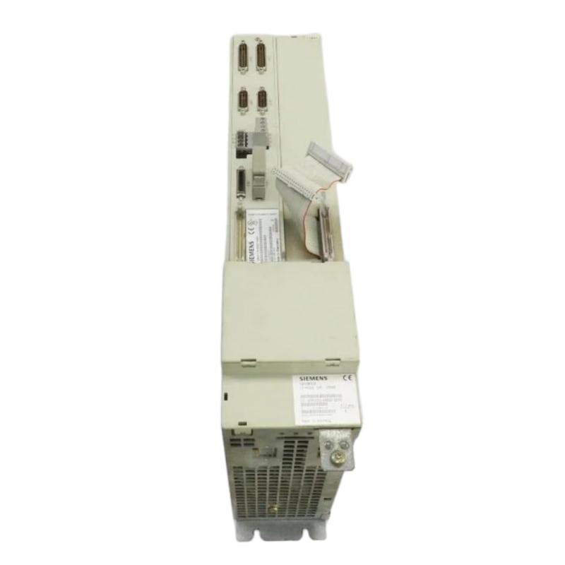
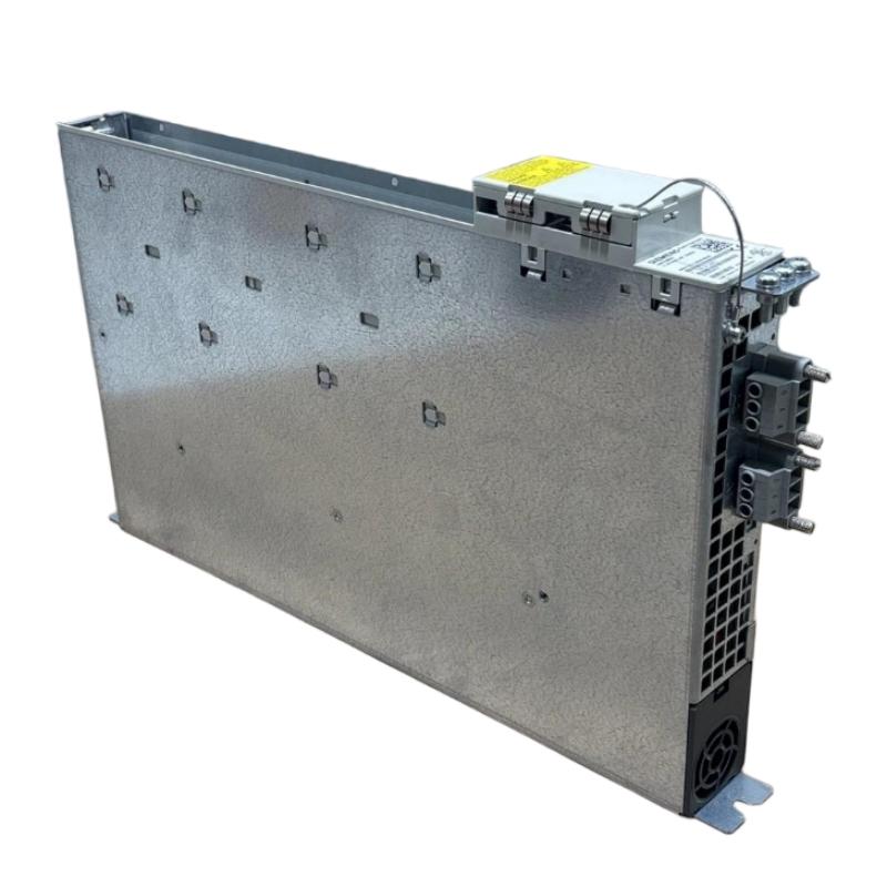
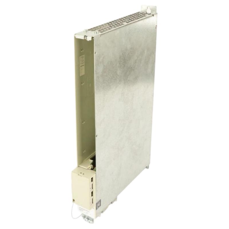
Contact Us
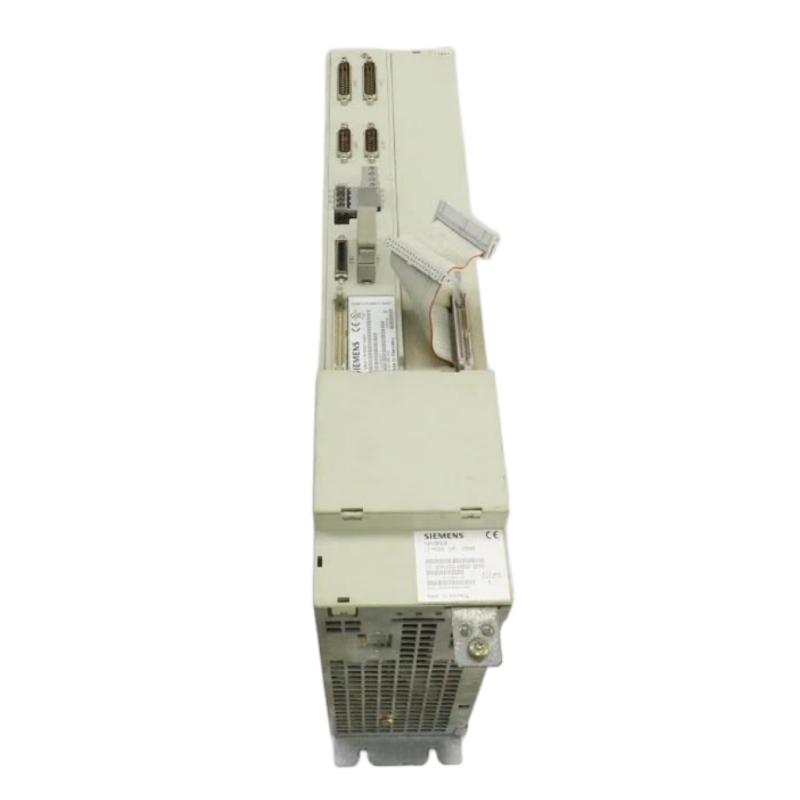
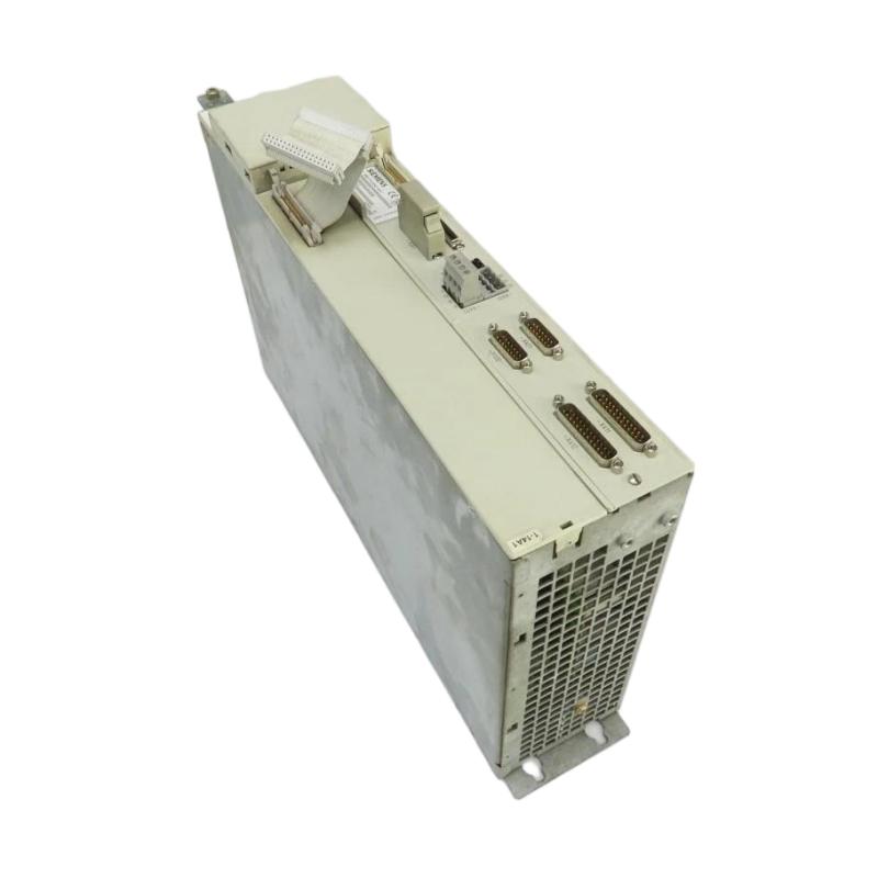
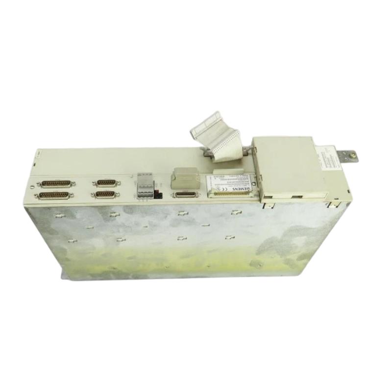
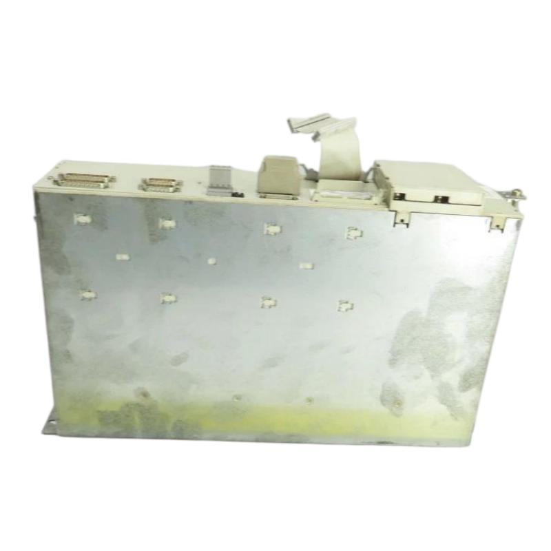
- Siemens
- 6SN1123-1AB00-0CA0
- Power Module
- Germany
- 102 × 483 × 305 mm
- 10 kg
- Xiamen, China
- New & In Stock
- T/T, PayPal, Western Union
- 1 Year
- 1-3 Working Days
- DHL, UPS, TNT, FedEx and EMS.
- 24-Hour Service
- COO
- 5
Our advantage

Global Logistics
We have a 10-year logistics and express cooperation agreement, so our products can be shipped to any place in the world.

Brand new and original
Our products are imported in bulk from the place of origin. Because of the cooperative relationship, our products are all original and 100% new.

24-hour service
We provide 7*24 hours service to our customers. We will be there whenever you need us.

Price advantage
All our products are priced very favorably because we have our own warehouse and supply.
| Company Information | |||
| [email protected] | |||
| Mobile | +8615980777398 | ||
| +8615980777398 | |||
| 15980777398 |
Product Overview
The Siemens 6SN1123-1AB00-0CA0 Power Module is an industrial drive component associated with Siemens SIMODRIVE technology, designed for integration into compatible motion-control and CNC automation systems. Power modules are essential elements in industrial drive architectures because they support the electrical power conversion and motor-control functions required for automated machinery. In applications involving precision movement, coordinated axes, and continuous production, selecting the correct module is critical to maintaining stable equipment operation.
Within a compatible Siemens drive installation, the power module operates alongside associated power-supply equipment, control electronics, motors, feedback devices, and machine controllers. These components work together to translate machine commands into controlled motor movement. The overall performance of the system depends on appropriate component matching, correct electrical installation, suitable cooling, and accurate drive configuration.
The 6SN1123-1AB00-0CA0 should be identified by its complete Siemens order number when planning installation, maintenance, or replacement. Modules within the same product family may have different power ratings, motor configurations, electrical characteristics, and system requirements. Consequently, a similar appearance or matching product-family designation is not sufficient to establish interchangeability.
The supplied physical specifications list the module at 102 × 483 × 305 mm, with a weight of approximately 10 kg. These measurements are useful for equipment identification, cabinet planning, storage, and handling. Before installation, technicians should verify the dimensions and mounting arrangement against the actual unit and the relevant equipment configuration.
Technical Specifications
| Parameter | Specification |
|---|---|
| Manufacturer | Siemens |
| Model | 6SN1123-1AB00-0CA0 |
| Product Family | SIMODRIVE |
| Product Type | Power Module |
| Primary Function | Drive-system power handling |
| Application Area | Industrial motion control and CNC machinery |
| System Integration | Compatible Siemens drive architecture |
| Dimensions | 102 × 483 × 305 mm |
| Weight | 10 kg |
| Installation | Industrial electrical cabinet or designated drive mounting assembly |
| Compatibility | Requires verification against the original system configuration |
| Electrical Ratings | Confirm from the module nameplate and applicable technical documentation |
| Supported Motor Configuration | Confirm for the exact module and host drive system |
The exact electrical ratings, supported motor arrangement, connector assignments, and control requirements should be verified for the specific 6SN1123-1AB00-0CA0 unit before commissioning or replacement.
Function and Working Principle
The Siemens 6SN1123-1AB00-0CA0 is intended to function as part of a coordinated industrial drive installation. In a typical drive architecture, electrical energy is supplied to the power section, processed by the drive electronics, and delivered to a compatible motor according to the requirements of the machine.
The exact internal design and electrical role of an individual module depend on its configuration. For this reason, the complete drive system and the module’s technical identification should be considered when determining its operating function.
Electrical Power Management
Industrial motors require electrical power that is appropriate for their rated operating conditions. A drive system manages this power to support the required motor operation. The power module forms part of that arrangement and must be matched with the relevant supply, motor, and associated drive components.
Interaction with Control Electronics
Drive-control electronics process commands from the machine controller and coordinate the drive’s response. The power section then supports the electrical functions needed for motor operation. Correct interaction between these sections is necessary for reliable movement, effective fault handling, and stable machine performance.
Support for Automated Motion
In CNC and industrial motion-control systems, motors may operate machine axes, spindles, positioning mechanisms, or other mechanical assemblies. A properly selected drive module contributes to the overall system’s ability to execute movement commands within the machine’s designed operating limits.
Monitoring and Fault Response
The complete drive installation may provide diagnostic information relating to electrical conditions, temperature, control status, or motor operation. When a fault occurs, the reported alarm and operating history should be examined before determining whether the power module is responsible.
Role in Industrial Automation Systems
The 6SN1123-1AB00-0CA0 can be considered one component within a broader industrial motion-control architecture. Its practical role depends on the Siemens drive configuration in which it is installed.
A typical automation arrangement may include a machine controller, drive-control electronics, power modules, motors, feedback devices, operator interfaces, and electrical protection equipment. Each element has a defined function, and compatibility across the system is essential.
Key system-level responsibilities include:
- Supporting electrical power delivery within the drive system.
- Contributing to controlled motor operation.
- Working with control electronics to execute machine commands.
- Supporting automated positioning and motion-related functions.
- Providing a replaceable component for industrial maintenance.
- Maintaining integration with the existing machine electrical architecture.
For maintenance teams, identifying the exact module and understanding its relationship with the surrounding components can help reduce unnecessary replacements and shorten troubleshooting time.
Industrial Applications
CNC Machine Tools
CNC machine tools use coordinated drive systems to control movement during machining operations. Siemens drive components may be integrated into the electrical architecture that operates machine axes and other motor-driven functions. Proper component matching is important for maintaining predictable machine behavior.
Milling and Turning Machines
Milling machines, lathes, and related equipment rely on drive systems to operate motors under varying load conditions. Drive components must be suitable for the specific machine configuration and its operating requirements.
Automated Manufacturing Equipment
Industrial production lines use motors for feeding, positioning, indexing, material movement, and other automated operations. A compatible power module can support the drive architecture responsible for these functions.
Material Processing Machinery
Equipment used in metalworking, fabrication, and other processing operations may require reliable motor control for repetitive production tasks. Drive-system performance depends on the combined condition of the electrical, mechanical, and control components.
Legacy Siemens Automation Installations
Many production facilities maintain existing Siemens drive equipment because it forms part of an established machine or production line. When a module fails, accurate identification and compatibility verification are essential before installing a replacement.
Installation and System Integration
Installation should be carried out by qualified personnel familiar with industrial power electronics and the relevant Siemens drive system. Incorrect handling or incompatible replacement parts can create electrical hazards and equipment damage.
1. Confirm the Model Number
Check the complete 6SN1123-1AB00-0CA0 designation on the module label. Record any additional revision or identification markings and compare them with the original equipment records.
Do not select a replacement based only on the SIMODRIVE family name, physical dimensions, or a similar-looking enclosure.
2. Isolate the Equipment Safely
Before removing the module, shut down the machine using the approved procedure and isolate all relevant power sources. Follow the site’s lockout/tagout requirements and verify that hazardous voltage is absent.
Drive systems may retain dangerous electrical energy after power has been disconnected. Observe the specified discharge time and safety instructions before opening or handling the equipment.
3. Inspect the Mounting Assembly
Check the designated mounting location for mechanical damage, loose hardware, contamination, and evidence of overheating. Confirm that the available space and mounting arrangement are appropriate for the replacement.
The listed dimensions of 102 × 483 × 305 mm and weight of 10 kg should be considered during handling and cabinet-layout checks. Actual mounting requirements must be verified against the installed equipment.
4. Examine Electrical Connections
Inspect accessible connectors, power wiring, control connections, and associated cables for damage or signs of excessive heat. Record the original wiring arrangement before disconnecting the existing module.
Reconnect all components according to the applicable equipment documentation. Never assume that connector similarity guarantees identical pin assignments or electrical functionality.
5. Verify Drive-System Compatibility
Confirm that the module matches the system’s required electrical characteristics, motor arrangement, power architecture, and control configuration. Also inspect associated components that could have contributed to the original fault.
6. Complete Commissioning Checks
Before restoring normal operation, verify mounting security, grounding, wiring, cooling, and configuration. Apply power only after the required installation checks have been completed.
During initial operation, monitor the system for abnormal indications and verify that the machine performs its required functions. Follow the equipment’s approved commissioning and safety procedures before returning it to production.
Troubleshooting the Siemens 6SN1123-1AB00-0CA0
A drive-system fault does not automatically mean that the power module has failed. Problems may originate in the supply system, motor wiring, control electronics, feedback devices, cooling arrangement, or mechanical equipment.
Drive System Does Not Start
If the machine fails to start, review the reported fault codes and system status. Check whether the necessary power and control conditions are present and whether machine interlocks are preventing operation.
Potential causes include:
- An abnormal or missing power supply.
- An active machine or drive interlock.
- Loose or damaged electrical connections.
- Incorrect drive configuration.
- A fault in an associated component.
- A defective power module.
The fault should be diagnosed systematically before any component is replaced.
Drive Trips During Operation
Unexpected shutdowns may be triggered by electrical abnormalities, thermal conditions, motor problems, control faults, or excessive mechanical load.
Record the alarm information and the conditions under which the shutdown occurs. Inspect the cooling arrangement, power connections, motor cables, and driven mechanism. Repeatedly resetting the system without identifying the cause may lead to further downtime or equipment damage.
Abnormal Motor Operation
If a motor fails to operate as expected, investigate the drive configuration, motor connections, feedback signals, and mechanical load. Incorrect settings or faults in related equipment can produce symptoms that resemble a power-module failure.
Compare the available diagnostic information with the machine’s normal operating conditions before deciding on a repair.
Overheating or Restricted Cooling
Excessive temperature can reduce the reliability of industrial electronic equipment. Check for blocked airflow, accumulated dust, failed cabinet cooling equipment, and environmental conditions outside the specified operating range.
Any cleaning or inspection should be performed using approved procedures with the equipment safely isolated.
Recurring or Intermittent Alarms
Intermittent problems may be associated with loose connections, damaged cables, vibration, unstable supply conditions, temperature changes, or faults elsewhere in the drive system.
Maintain a record of the alarm codes, operating conditions, and corrective actions. Comparing these records can help identify recurring patterns and narrow the possible causes.
Preventive Maintenance Recommendations
A structured maintenance program helps improve drive-system reliability and reduce unexpected interruptions.
Visual inspection: Examine the module and surrounding cabinet for physical damage, contamination, discoloration, or signs of overheating.
Cooling-system checks: Confirm that ventilation passages remain clear and that the cabinet cooling arrangement functions correctly. Follow the specified maintenance procedure when removing dust or debris.
Connection inspection: Check accessible wiring and connectors for damage, loose fittings, or evidence of excessive temperature. Perform electrical inspections only when the equipment has been placed in a safe condition.
Alarm-history review: Review recorded faults and machine stoppages. Repeated alarms can indicate a developing problem in the power system, control architecture, motor, or mechanical load.
Environmental control: Maintain the cabinet within the environmental conditions specified for the equipment. Excessive dust, moisture, heat, and vibration can contribute to premature component failure.
Maintenance documentation: Record the installed part number, revision information, fault history, replacement date, and commissioning results. Accurate records simplify future troubleshooting and procurement.
Compatible System Components
The Siemens 6SN1123-1AB00-0CA0 should be evaluated as part of its complete drive installation. Depending on the application, the surrounding system may include the following component categories.
| Component Category | Typical Function |
|---|---|
| Compatible Siemens drive power supply | Provides the electrical supply required by the drive configuration |
| Drive-control electronics | Processes commands and coordinates drive operation |
| Compatible motor-drive components | Support the motor arrangement specified by the system design |
| CNC or machine controller | Coordinates machine movement and operating sequences |
| Servo or spindle motor | Converts electrical power into mechanical movement |
| Feedback devices | Provide position or speed information where required |
| Motor and power cables | Connect drive equipment with the associated motor |
| Cabinet cooling equipment | Maintains suitable thermal conditions |
| Electrical protection equipment | Supports safe isolation and protection |
| Operator interface | Displays machine status, alarms, and diagnostic information |
These are general component categories, not a confirmed compatibility list for every installation. Exact part selection should be based on the original machine configuration and the applicable technical information.
Replacement and Procurement Guide
When sourcing a replacement Siemens 6SN1123-1AB00-0CA0 Power Module, verify the exact product identity and the requirements of the host system.
Before ordering, check the following:
- Complete Siemens order number.
- Additional product and revision markings.
- Existing drive-system configuration.
- Required electrical ratings.
- Supported motor arrangement.
- Connector and mounting details.
- Condition of related power and control components.
- Physical dimensions and handling requirements.
- Suitability of the replacement for the intended installation.
The listed dimensions are 102 × 483 × 305 mm, and the listed weight is approximately 10 kg. These values can assist with logistics and cabinet planning, but they do not independently establish functional interchangeability.
For older industrial systems, retaining photographs of the identification label, wiring arrangement, and installation position can help maintenance personnel verify the correct replacement. Any substitute should be approved for the particular drive configuration before installation.
Key Advantages
Integration with Industrial Drive Architectures
The module is associated with Siemens SIMODRIVE technology and is intended for use within a compatible drive installation.
Support for Motor-Driven Machinery
When correctly matched to the system, it contributes to the power architecture used to operate industrial motors.
Useful for Equipment Maintenance
The complete order number supports identification, maintenance records, and replacement planning.
Practical Installation Information
The listed dimensions and weight help maintenance teams plan storage, handling, and cabinet-space requirements.
System-Level Reliability
Long-term reliability depends on correct component selection, appropriate cooling, sound electrical connections, and proper commissioning of the complete drive system.
Technical FAQs
What is the Siemens 6SN1123-1AB00-0CA0?
It is a Siemens power module associated with SIMODRIVE drive technology. Its precise electrical function and supported configuration should be confirmed using the exact module identification and host-system requirements.
What are the dimensions of the 6SN1123-1AB00-0CA0?
The supplied dimensions are 102 × 483 × 305 mm.
How much does the module weigh?
The supplied weight is approximately 10 kg.
Can it replace another Siemens SIMODRIVE module?
Not automatically. The replacement must be checked for electrical ratings, motor configuration, connectors, revision, and compatibility with the installed drive system.
What should be checked if the drive fails to start?
Review the fault codes, supply conditions, machine interlocks, control status, wiring, and associated drive components. A module replacement should be considered only after the likely cause has been identified.
Why is preventive maintenance important?
Regular inspection can reveal cooling restrictions, loose connections, contamination, and recurring fault patterns before they cause extended downtime.
Are the dimensions enough to identify a compatible replacement?
No. Physical dimensions support identification and installation planning, but the complete part number and technical compatibility are more important.
What safety precautions are required during replacement?
Qualified personnel should follow the approved isolation and lockout/tagout procedure, verify the absence of hazardous voltage, and observe the specified discharge time before handling the equipment.
Conclusion
The Siemens 6SN1123-1AB00-0CA0 Power Module is an industrial drive component associated with Siemens SIMODRIVE technology and intended for integration into compatible motion-control and CNC installations. As part of a complete drive architecture, it contributes to the electrical power functions required for controlled motor operation and automated machine movement.
With supplied dimensions of 102 × 483 × 305 mm and a weight of approximately 10 kg, the module can be identified for equipment maintenance, inventory management, and replacement planning. Reliable operation depends on correct system matching, proper electrical installation, suitable cooling, and careful commissioning.
Before ordering or installing a replacement, verify the complete 6SN1123-1AB00-0CA0 model designation and confirm compatibility with the original drive configuration. Accurate identification and systematic maintenance help reduce replacement errors, limit production downtime, and support the long-term operation of industrial automation equipment.