

ProductPRODUCT
Featured products
Contact Us
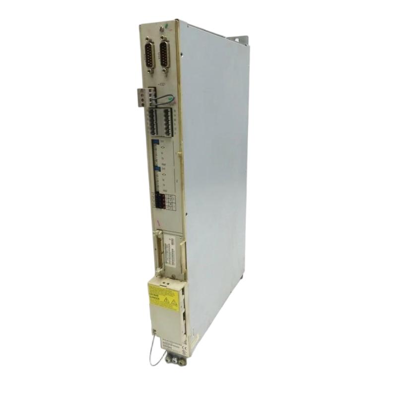
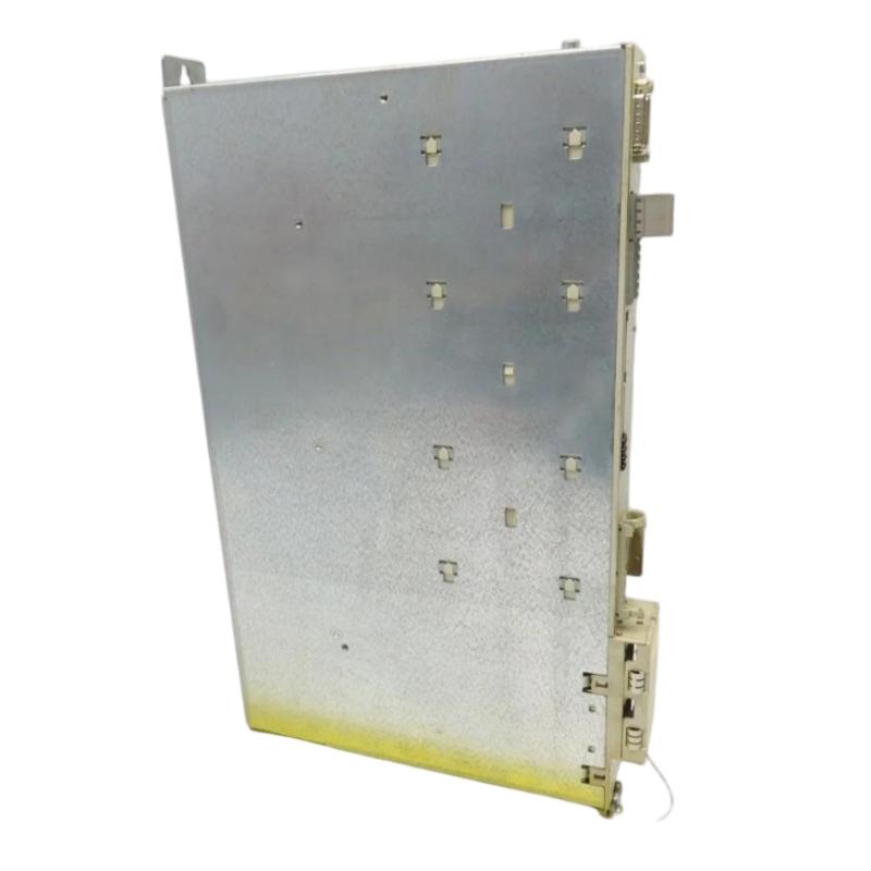
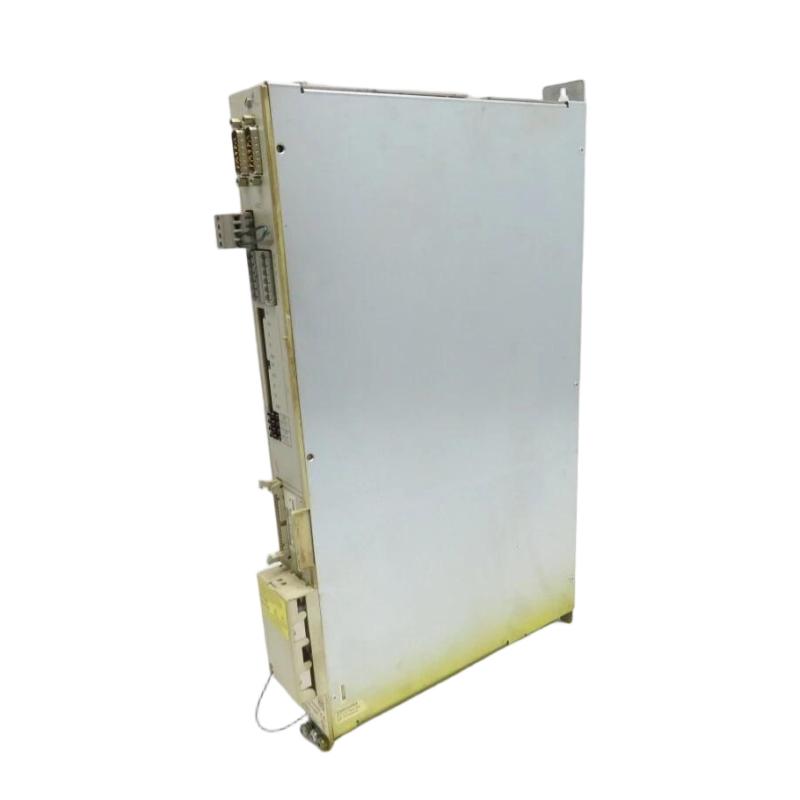
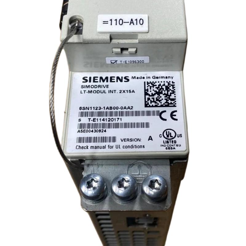
- Siemens
- 6SN1123-1AB00-0AA2
- Power Module
- Germany
- 305 × 51 × 533 mm
- 6.25 kg
- Xiamen, China
- New & In Stock
- T/T, PayPal, Western Union
- 1 Year
- 1-3 Working Days
- DHL, UPS, TNT, FedEx and EMS.
- 24-Hour Service
- COO
- 5
Our advantage

Global Logistics
We have a 10-year logistics and express cooperation agreement, so our products can be shipped to any place in the world.

Brand new and original
Our products are imported in bulk from the place of origin. Because of the cooperative relationship, our products are all original and 100% new.

24-hour service
We provide 7*24 hours service to our customers. We will be there whenever you need us.

Price advantage
All our products are priced very favorably because we have our own warehouse and supply.
| Company Information | |||
| [email protected] | |||
| Mobile | +8615980777398 | ||
| +8615980777398 | |||
| 15980777398 |
Product Overview
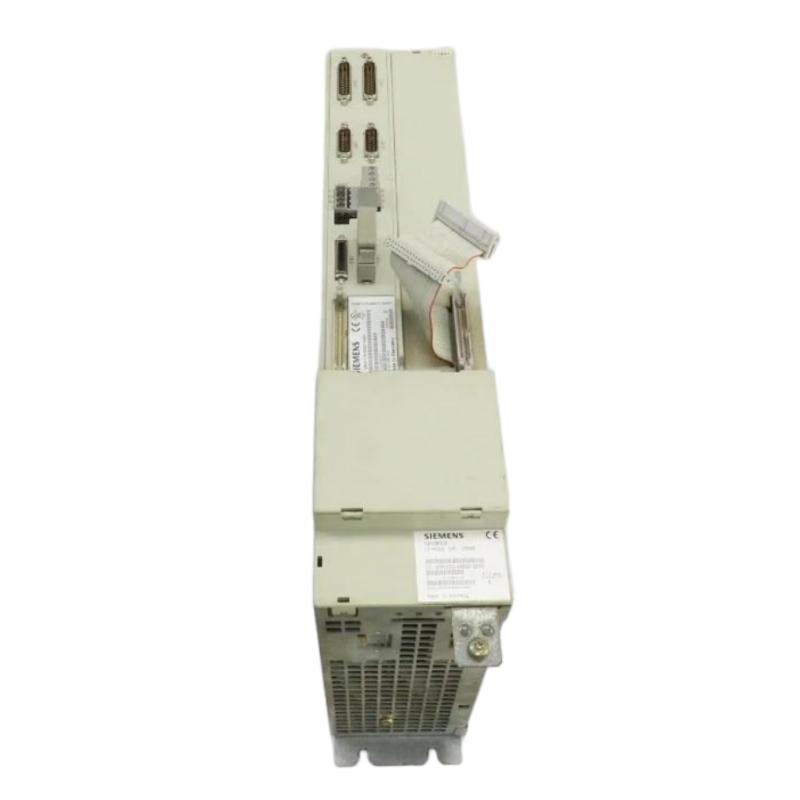
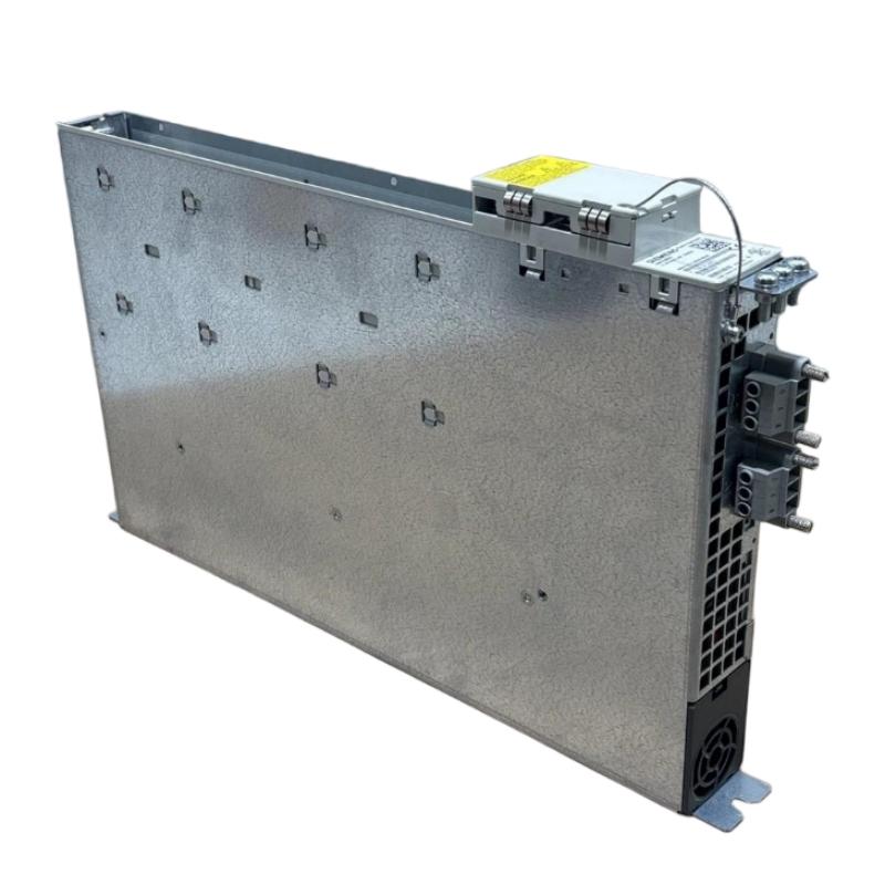
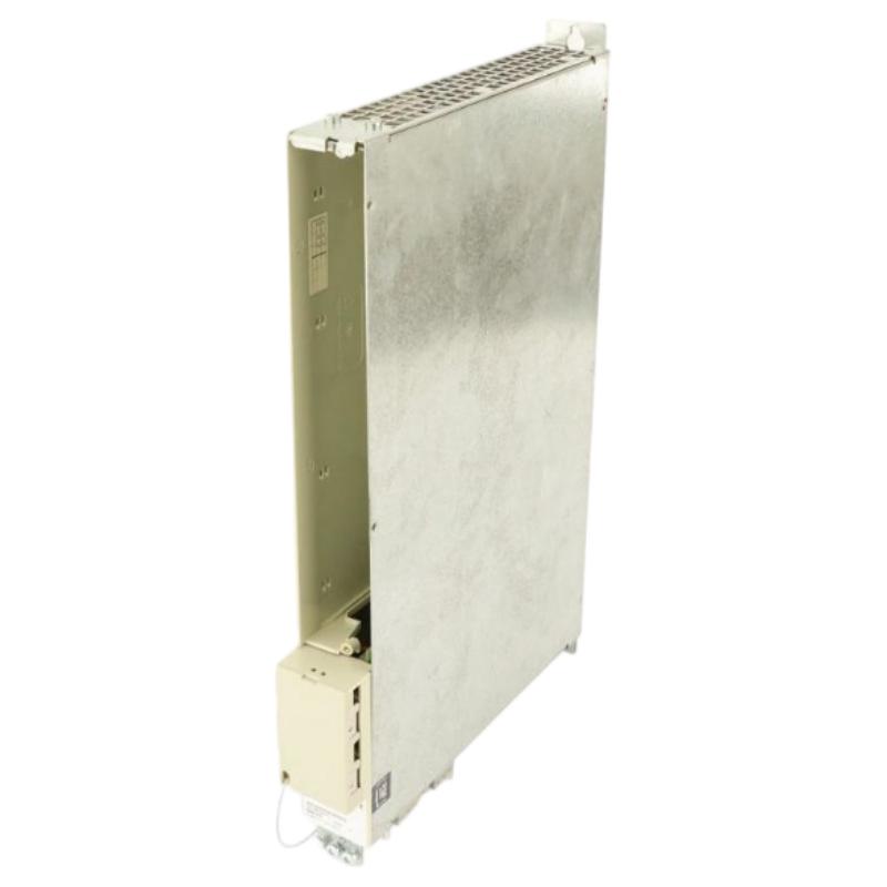
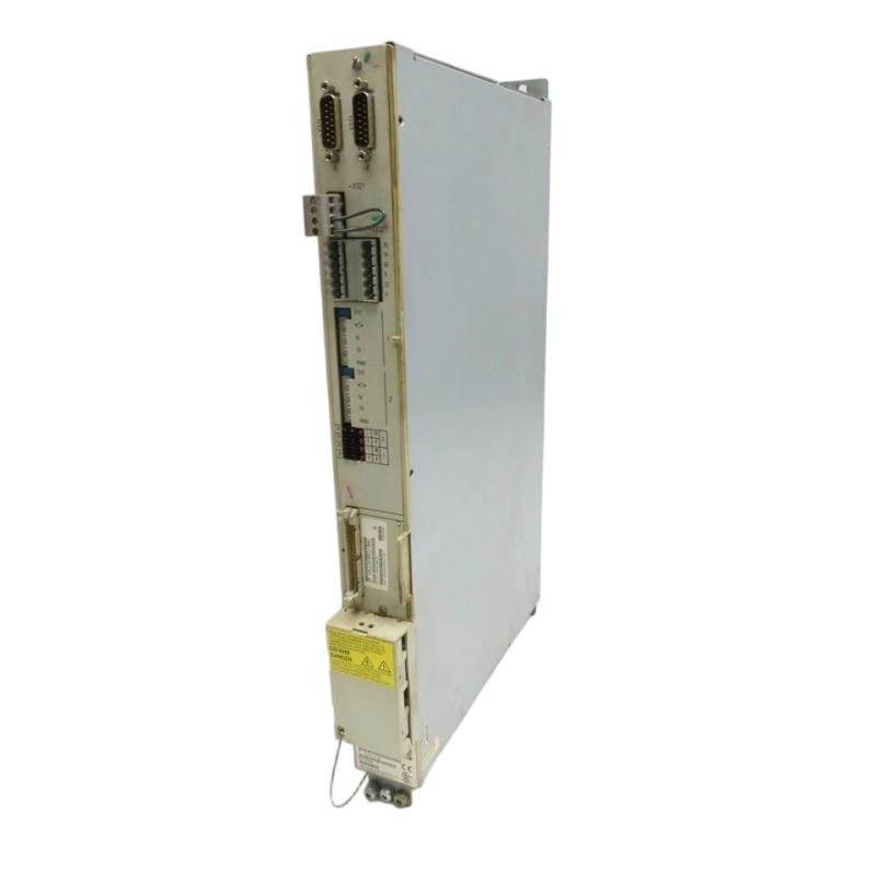
The Siemens 6SN1123-1AB00-0AA2 Power Module is an industrial drive component associated with the Siemens SIMODRIVE 611 drive system. Designed for integration into compatible drive configurations, power modules play an important role in supplying and controlling the electrical power required by servo motors and other supported motion-control equipment.
In CNC machines, machine tools, and automated manufacturing systems, reliable drive operation is essential for accurate positioning, controlled acceleration, and consistent production performance. A drive power module works as part of a larger system that includes control electronics, power conversion components, feedback devices, motor cabling, and protective equipment. Correct coordination between these components helps maintain stable machine operation and reduces the risk of unexpected downtime.
The Siemens 6SN1123-1AB00-0AA2 is identified by its complete order number, which should be retained when checking compatibility or sourcing a replacement. Its listed dimensions are 305 × 51 × 533 mm, and its listed weight is approximately 6.25 kg. These specifications are useful for equipment identification, cabinet planning, transportation, and spare-parts management.
Because SIMODRIVE drive components are designed for specific system configurations, the exact electrical ratings, supported motor arrangements, and compatibility requirements should be verified against the installed drive system before commissioning or replacement.
Technical Specifications
| Parameter | Specification |
|---|---|
| Manufacturer | Siemens |
| Model | 6SN1123-1AB00-0AA2 |
| Product Type | Power Module |
| Product Family | SIMODRIVE 611 |
| Product Category | Industrial Drive System Component |
| Primary Function | Drive power conversion and motor-power control within a compatible system |
| Typical Application | CNC machines and industrial motion-control equipment |
| System Integration | Compatible SIMODRIVE drive configuration |
| Dimensions | 305 × 51 × 533 mm |
| Weight | 6.25 kg |
| Installation | Compatible drive cabinet or designated mounting assembly |
| Electrical Ratings | Verify from the exact model documentation and nameplate |
| Motor Compatibility | Confirm the supported motor and drive configuration |
| Cooling Requirements | Follow the applicable drive-system installation requirements |
| Replacement Requirement | Match the complete order number and system configuration |
What Is the Siemens 6SN1123-1AB00-0AA2 Power Module?
The Siemens 6SN1123-1AB00-0AA2 is a power-module component identified with the SIMODRIVE 611 family. In industrial motion-control systems, a power module provides the electrical power stage required for controlled motor operation as part of the overall drive architecture.
Unlike a standalone controller, a drive power module normally operates alongside control electronics that determine the required motor response. The controller processes commands and feedback information, while the drive power stage handles the electrical energy needed to produce the requested motor behavior.
This arrangement is important in CNC machining centers, lathes, milling machines, and other automated production equipment. These applications often require coordinated motor operation, repeatable positioning, controlled acceleration, and reliable performance over extended operating periods.
The complete Siemens order number is essential when identifying the correct module. Components that look similar or belong to the same SIMODRIVE family may differ in their electrical ratings, motor compatibility, or intended system position.
Function and Working Principle
1. Power Conversion
Industrial drive systems receive electrical power from an incoming supply and convert it into the form required by the connected motor. The power module forms part of this conversion process within the compatible SIMODRIVE architecture.
The exact conversion topology and electrical limits depend on the specific module and drive configuration. These details must be confirmed before connecting the unit to a machine.
2. Motor Power Regulation
The drive system regulates the electrical power delivered to the motor according to commands from the control electronics. This enables the machine to control motion rather than simply switching the motor on or off.
Depending on the application and installed drive configuration, controlled motor operation can support acceleration, deceleration, speed regulation, and coordinated movement.
3. Interaction with Control Electronics
A drive power module does not operate in isolation. It must work with the corresponding control and interface components to interpret commands, manage operating conditions, and respond appropriately to system faults.
Incorrect pairing between power and control components can prevent startup or result in drive faults. System compatibility should therefore be confirmed using the complete module designation and the requirements of the installed equipment.
4. Protection and Fault Response
Industrial drive systems incorporate protective mechanisms to respond to abnormal electrical or operating conditions. Depending on the complete system, monitoring may involve current, voltage, temperature, feedback, and other operating parameters.
The actual protection functions available for the 6SN1123-1AB00-0AA2 should be verified from the applicable documentation rather than inferred from the general capabilities of the SIMODRIVE family.
5. Continuous Industrial Operation
In manufacturing environments, drive equipment may operate for long production cycles. Appropriate installation, cooling, electrical protection, and preventive maintenance help maintain stable operation and reduce avoidable interruptions.
Role in CNC and Industrial Motion-Control Systems
The Siemens 6SN1123-1AB00-0AA2 can form part of a larger motion-control system in which the control unit, power electronics, motor, and feedback components work together.
A typical drive architecture may include:
- CNC or machine controller.
- Drive control electronics.
- Compatible power module.
- Servo or other supported drive motor.
- Motor power and feedback cables.
- Position or speed feedback devices, where required.
- Protective devices and electrical distribution.
- Cooling and cabinet ventilation equipment.
The controller determines the required movement, while the drive system provides the electrical power and control needed to achieve it. This coordination allows machine axes and other driven mechanisms to operate according to the programmed manufacturing sequence.
The precise architecture depends on the machine design and installed SIMODRIVE configuration. The listed model should not be assumed to support every motor or drive arrangement in the product family.
Industrial Applications
CNC Machining Centers
CNC machining centers require controlled movement for cutting, drilling, milling, and related operations. Drive-system power modules support the electrical side of motion control when correctly matched to the installed system.
Stable drive operation contributes to repeatable machine performance and reliable production cycles.
CNC Lathes and Turning Machines
Turning machines depend on coordinated motor operation for spindle and axis movements. Compatible drive components help supply the power required by the machine’s motion-control architecture.
Milling and Grinding Equipment
Milling and grinding applications can require controlled acceleration, stable movement, and consistent operation. A properly configured drive system helps the machine execute the required motion profile.
Automated Manufacturing Lines
Industrial production lines may use coordinated drives to move workpieces, position tooling, and operate auxiliary mechanisms. Power modules can support these functions as part of a compatible drive platform.
Machine Tool Retrofitting and Maintenance
During machine refurbishment, technicians may need to replace a failed drive component while preserving the existing control architecture. Correct part identification is essential to prevent compatibility problems and unnecessary commissioning delays.
Installation and System Integration
Installation should be performed by qualified personnel familiar with industrial drive systems. Incorrect electrical connections or unsuitable replacement components can damage equipment and create serious safety hazards.
Verify the Complete Order Number
Before installation, confirm that the module is marked 6SN1123-1AB00-0AA2. Check the identification label, revision information where applicable, connector arrangement, and designated installation position.
Do not select a replacement based only on dimensions or visual similarity.
Inspect the Drive Cabinet
Check the mounting area for contamination, mechanical damage, loose connections, and signs of overheating. Ensure that the cabinet and cooling arrangement meet the requirements of the installed drive system.
The listed dimensions of 305 × 51 × 533 mm should be used for preliminary planning, with additional space provided where required for mounting, electrical connections, airflow, and servicing.
Confirm Electrical Compatibility
Before connecting the module, verify the supply arrangement, electrical ratings, protective devices, grounding requirements, and connection diagrams for the exact unit.
Drive-system components may operate with hazardous voltages and can retain stored electrical energy after the incoming supply is disconnected. Follow the prescribed isolation and discharge procedures before handling terminals or internal components.
Check Motor and Control-System Compatibility
Confirm that the power module is suitable for the installed motor and the associated control electronics. Check the required feedback arrangements, motor cables, and system configuration.
A replacement module should match the requirements of the complete drive system, not merely the nominal motor power.
Verify Cooling and Ventilation
Power electronics generate heat during operation. Ensure that cooling paths are clear and that the installation provides the airflow or other cooling conditions required by the system.
Blocked ventilation, contaminated heat-transfer surfaces, or unsuitable cabinet temperatures can contribute to thermal faults and reduced service life.
Commission the Drive
After installation, inspect all connections and confirm that the correct parameters and system configuration are in place. Use the approved commissioning procedure to check startup behavior, fault indications, and motor operation.
Where practical, test the equipment under controlled conditions before returning the machine to production. Record the module identification and any configuration changes made during the replacement.
Troubleshooting the Siemens 6SN1123-1AB00-0AA2
Drive problems can originate from the power module, control electronics, incoming supply, motor, feedback system, cooling arrangement, or external machine conditions. A fault indication alone does not prove that the power module has failed.
Drive Fails to Start
Possible causes include an interrupted supply, an incompatible system configuration, an active interlock, a control-system problem, or a power-module fault.
Recommended checks:
- Review the drive and machine fault indications.
- Confirm the incoming supply and protective devices.
- Check connectors and external wiring.
- Verify that the control electronics are communicating and configured correctly.
- Confirm that all required startup conditions are satisfied.
Electrical measurements should be performed only by qualified personnel using approved procedures.
Overtemperature or Thermal Fault
A thermal fault may be associated with insufficient airflow, excessive ambient temperature, contamination, sustained high loading, or a problem within the drive system.
Inspect the cooling arrangement and cabinet environment. Confirm that ventilation paths are unobstructed and that the system is operated within its specified limits.
Do not repeatedly reset a thermal fault without identifying the underlying cause.
Unexpected Drive Trips
Repeated trips may be caused by supply disturbances, motor or cable problems, unsuitable parameters, mechanical overload, or an internal drive fault.
Record the exact fault indication and the operating conditions at the time of failure. Check the motor, cabling, machine mechanics, and associated control components before deciding that the power module requires replacement.
Motor Does Not Operate Correctly
Incorrect motor behavior may result from a control-command issue, feedback fault, wiring problem, configuration mismatch, or a drive power-stage problem.
Check whether the control system is issuing the expected command and whether the feedback signals are valid. Verify motor and drive compatibility against the approved configuration.
Repeated Faults After Replacement
If a replacement module produces the same fault as the original unit, investigate the wider system. Potential causes include incorrect wiring, an unsuitable replacement, faulty external components, cooling problems, or incorrect configuration.
Compare the complete part numbers and verify the installation against the system design. Replacing modules repeatedly without a structured diagnosis can increase downtime and risk further equipment damage.
Maintenance Recommendations
Preventive maintenance helps reduce unexpected drive-system failures and supports stable machine operation.
Inspect electrical connections. Look for loose connectors, damaged insulation, discoloration, corrosion, or signs of overheating. Perform inspections only after the equipment has been safely isolated.
Maintain cooling conditions. Keep ventilation paths clear and maintain the cabinet environment within the specified operating limits. Investigate repeated temperature alarms instead of treating them as routine interruptions.
Monitor drive fault history. Record recurring faults and the conditions under which they occur. Trends can help identify developing problems in the supply, motor, feedback system, or cooling arrangement.
Inspect associated components. Check relevant motor cables, feedback cables, control interfaces, and protective devices as part of the wider drive-system maintenance plan.
Maintain configuration records. Record the exact module order number, installation position, and relevant drive parameters. Preserve approved configuration backups where supported by the system.
Use correct replacement parts. Confirm the complete order number and required compatibility before fitting a replacement. A similar-looking module may not provide the same electrical or functional characteristics.
Compatible System Components
The 6SN1123-1AB00-0AA2 should be integrated only into a compatible SIMODRIVE system. Depending on the machine configuration, the wider installation may include the following components.
| Component | Typical Function |
|---|---|
| Siemens CNC or Machine Controller | Generates machine commands and coordinates motion |
| Compatible SIMODRIVE Control Electronics | Manages drive operation and control functions |
| SIMODRIVE Power Components | Provide the electrical power stage required by the drive system |
| Compatible Servo Motor | Converts electrical power into controlled mechanical motion |
| Motor Power Cable | Carries electrical power between the drive and motor |
| Feedback Cable or Device | Provides position or speed information where required |
| Electrical Protection Devices | Support protection of the supply and associated circuits |
| Cooling and Ventilation Equipment | Maintains suitable operating temperatures |
| Machine Control Cabinet | Houses the drive and associated control components |
This list describes the general system architecture. It does not confirm that every component is directly compatible with the 6SN1123-1AB00-0AA2. The actual configuration must be checked against the machine’s installed equipment and technical requirements.
Replacement and Procurement Considerations
When sourcing a replacement for the Siemens 6SN1123-1AB00-0AA2 Power Module, exact identification is critical. Industrial drive modules may share similar housings while differing in electrical characteristics, supported motors, control interfaces, or intended applications.
Before ordering, verify:
- Complete order number: 6SN1123-1AB00-0AA2.
- Product identification and revision details.
- Compatibility with the existing SIMODRIVE system.
- Electrical ratings and supply requirements.
- Supported motor and control configuration.
- Connector and mounting arrangement.
- Cooling and installation requirements.
- Condition and fault history of the existing unit.
- Availability of the required commissioning information.
The listed dimensions are 305 × 51 × 533 mm, and the listed weight is approximately 6.25 kg. These measurements support equipment identification, cabinet planning, handling, and shipping preparation.
Before replacing the module, document the existing installation and review the original fault conditions. Confirm that the replacement is suitable for the installed configuration and that all required commissioning checks can be completed.
Technical FAQs
What is the Siemens 6SN1123-1AB00-0AA2?
It is identified as a Siemens power module associated with the SIMODRIVE 611 drive family and intended for use in a compatible industrial drive configuration.
What are the dimensions of the 6SN1123-1AB00-0AA2?
The listed dimensions are 305 × 51 × 533 mm.
How much does the 6SN1123-1AB00-0AA2 weigh?
The listed weight is approximately 6.25 kg.
What is the role of a power module in a drive system?
A power module provides part of the electrical power stage used to operate a compatible motor. It works with the associated control electronics and other drive components.
Can this module be used with any Siemens SIMODRIVE system?
No. Compatibility must be verified using the complete order number, electrical specifications, motor requirements, and the configuration of the installed drive system.
What can cause a drive-system fault?
Possible causes include supply disturbances, wiring problems, cooling issues, motor or feedback faults, configuration errors, mechanical overload, or an internal drive-component failure.
What should be checked before replacing the power module?
Verify the exact part number, investigate the original fault, check the supply and external wiring, confirm motor and control compatibility, and follow the approved isolation and commissioning procedures.
Why is cooling important for drive power modules?
Power electronics generate heat during operation. Suitable cooling and ventilation help keep components within their specified operating limits and reduce the risk of thermal faults.
Conclusion
The Siemens 6SN1123-1AB00-0AA2 Power Module is an industrial drive component associated with the SIMODRIVE 611 platform. As part of a compatible motion-control architecture, a power module supports the electrical power stage required for controlled motor operation in CNC machinery and other automated manufacturing equipment.
With listed dimensions of 305 × 51 × 533 mm and a weight of approximately 6.25 kg, the module can be identified and planned for as part of industrial drive maintenance and spare-parts management.
Reliable operation depends on correct system matching, proper electrical installation, suitable cooling, and systematic fault diagnosis. Before installation or replacement, verify the complete order number and the electrical and functional requirements of the existing drive system to support safe commissioning and dependable machine performance.