

ProductPRODUCT
Featured products
Contact Us
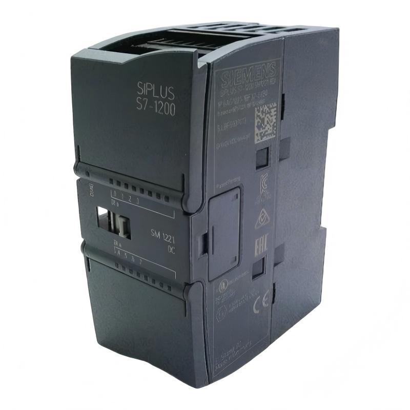
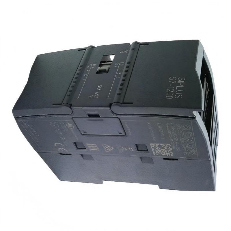
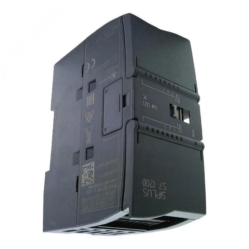
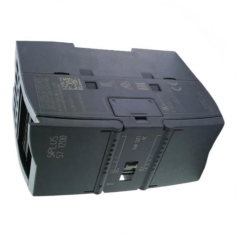
- Siemens
- 6AG1221-1BF32-2XB0
- Digital Input Module
- Germany
- 45 × 100 × 75 mm
- 0.16 kg
- Xiamen, China
- New & In Stock
- T/T, PayPal, Western Union
- 1 Year
- 1-3 Working Days
- DHL, UPS, TNT, FedEx and EMS.
- 24-Hour Service
- COO
- 4
Our advantage

Global Logistics
We have a 10-year logistics and express cooperation agreement, so our products can be shipped to any place in the world.

Brand new and original
Our products are imported in bulk from the place of origin. Because of the cooperative relationship, our products are all original and 100% new.

24-hour service
We provide 7*24 hours service to our customers. We will be there whenever you need us.

Price advantage
All our products are priced very favorably because we have our own warehouse and supply.
| Company Information | |||
| [email protected] | |||
| Mobile | +8615980777398 | ||
| +8615980777398 | |||
| 15980777398 |
Product Overview
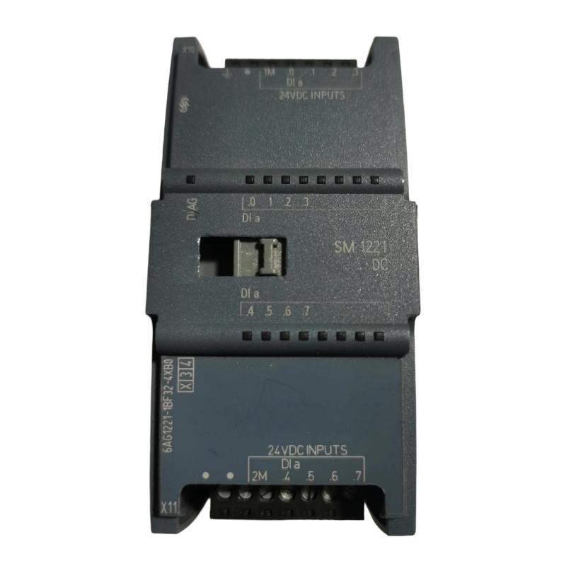
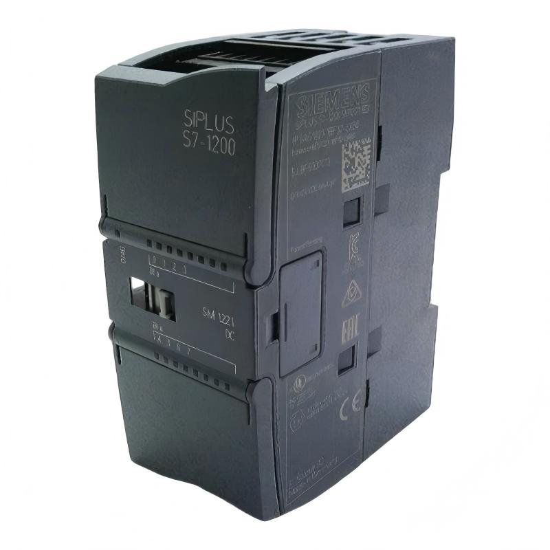
The Siemens 6AG1221-1BF32-2XB0 Digital Input Module is an industrial automation component intended for acquiring discrete signals from field devices and transferring input status information to a programmable logic controller (PLC) or compatible control system. Digital input modules play an important role in automated machinery, production lines, process equipment, and industrial monitoring systems by enabling controllers to respond to external switching conditions.
In a typical automation installation, field devices such as push buttons, selector switches, limit switches, auxiliary contacts, and compatible electronic sensors generate discrete signals. The digital input module provides the interface between these field signals and the controller’s processing logic. The PLC can then evaluate the received input states and execute the corresponding control program.
The Siemens 6AG1221-1BF32-2XB0 is identified by the supplied product description as a digital input module. Its listed dimensions are 45 × 100 × 75 mm, and its listed weight is 0.16 kg. This compact form factor can be useful in control cabinets where efficient space utilization and organized wiring are important.
Before installation or replacement, the complete order number should be checked against the installed hardware and the applicable Siemens product documentation. Electrical input characteristics, channel configuration, signal voltage, isolation, and supported controller families should be confirmed rather than inferred from the product name alone.
Technical Specifications
| Parameter | Specification |
|---|---|
| Manufacturer | Siemens |
| Model / Order Number | 6AG1221-1BF32-2XB0 |
| Product Type | Digital Input Module |
| Product Category | PLC Input / Industrial Automation |
| Primary Function | Acquisition of discrete field signals |
| Signal Type | Digital input signals; exact electrical characteristics require verification |
| System Role | Field-device interface for a compatible controller |
| Dimensions | 45 × 100 × 75 mm |
| Weight | 0.16 kg |
| Installation | Compatible control-system mounting arrangement; verify before installation |
| Typical Applications | Machine automation, equipment status monitoring, and industrial control |
| Compatibility | Confirm against the host PLC, hardware configuration, and system documentation |
The table includes the product identification and physical specifications supplied for this item. Details such as the number of input channels, rated input voltage, input-current thresholds, isolation method, and diagnostic capabilities should be verified using the exact order number and hardware revision.
What Is the Siemens 6AG1221-1BF32-2XB0?
A digital input module is an interface component that allows a PLC or industrial controller to detect discrete electrical states. Unlike an analog input module, which measures a continuously varying value such as temperature or pressure, a digital input module generally interprets a signal as one of two logical conditions, such as ON and OFF.
For example, a limit switch may indicate that a machine component has reached its travel limit. A push button may request a machine start or stop operation, while an auxiliary contact can report whether a motor starter or contactor has changed state.
The digital input module receives these signals and makes the corresponding input states available to the compatible control system. The PLC program can then use the information to control outputs, sequence machinery, trigger alarms, or record equipment status.
The basic signal path is:
Field Device → Input Wiring → Digital Input Module → PLC Processing → Control Response
The exact electrical interface and installation arrangement depend on the module’s verified specifications and the host automation platform.
Function and Working Principle
1. Discrete Signal Acquisition
The module’s primary role is to receive discrete electrical signals from connected field devices. These signals represent defined equipment or process states rather than continuously changing measurements.
Typical examples include:
- Push-button status
- Selector-switch position
- Limit-switch activation
- Proximity-sensor status
- Relay or contactor auxiliary-contact feedback
- Machine-door or guard-switch status, where the device and system design permit
- Equipment-running and equipment-ready indications
The input device and module must use compatible electrical signal characteristics. The supported voltage range and wiring method must be confirmed before connecting field equipment.
2. Input Signal Interpretation
A digital input interface determines whether the incoming signal corresponds to a valid logical state according to its electrical design. Input thresholds, filtering, and signal-conditioning behavior depend on the specific hardware.
Correct signal interpretation helps the controller distinguish a valid switching condition from an inactive input. Incorrect voltage levels, unsuitable wiring, electrical interference, or incompatible field devices may prevent reliable detection.
3. Data Transfer to the Controller
After the input state is recognized, the module makes that information available through its supported hardware interface. The controller uses the input data during execution of the configured control program.
The exact data-transfer mechanism depends on the product architecture and compatible controller. The order number should therefore be confirmed before defining the hardware configuration or communication arrangement.
4. PLC Logic Execution
The PLC program evaluates the received input states and determines the required response. Depending on the application, this may involve starting a motor, advancing a machine sequence, enabling an operation, stopping a process, or generating an alarm.
The digital input module acquires the field information; the control program determines how the system responds to it.
5. Continuous Equipment Monitoring
When installed in a suitable control system, digital inputs can provide ongoing feedback about equipment status. Operators and maintenance personnel can use these states to help identify incomplete sequences, unexpected switching conditions, or equipment that has failed to reach the required operating state.
Role in Industrial Control Systems
The Siemens 6AG1221-1BF32-2XB0 is intended, according to its supplied description, to serve as a digital signal acquisition component. In an industrial control architecture, this function helps connect physical equipment with the controller’s decision-making logic.
A typical control arrangement includes field devices, input interfaces, a controller, output interfaces, and final control elements. Each component performs a different role.
| System Component | Typical Function |
|---|---|
| Push Buttons and Selector Switches | Provide operator commands |
| Limit Switches | Detect mechanical position or travel limits |
| Discrete Sensors | Indicate the presence or status of an object or condition |
| Digital Input Module | Acquires compatible discrete field signals |
| PLC or Controller | Executes control logic and sequence operations |
| Digital Output Module | Sends discrete commands to compatible loads or interface devices |
| Relays and Contactors | Switch equipment under the control-system design |
| HMI or Operator Panel | Displays equipment status and operating messages |
| Industrial Network | Connects compatible automation devices when required |
The exact architecture varies by machine and controller family. All modules, wiring, and field devices must be selected for electrical and functional compatibility.
Industrial Applications
Manufacturing and Assembly Lines
Digital inputs are widely used to detect workpiece presence, confirm station positions, monitor operator commands, and identify whether a production step has been completed. A PLC can use these states to coordinate conveyor movement, assembly operations, and machine sequencing.
Packaging Machinery
Packaging equipment often relies on discrete feedback from product sensors, guards, switches, and mechanism-position detectors. These signals help the controller coordinate feeding, positioning, sealing, and transfer operations.
Conveyor and Material Handling Systems
Conveyors and material handling equipment may use digital inputs to monitor travel limits, product detection, motor feedback, and transfer-point status. These signals help control movement and coordinate equipment in a larger production process.
Pump and Utility Equipment
In suitable control panels, digital inputs can monitor discrete states such as pressure-switch activation, tank-level switch status, motor-running feedback, and equipment fault contacts. The input module does not itself measure a continuous process variable unless the connected device converts that variable into a compatible discrete signal.
Industrial Machine Tools
Machine tools may use discrete input signals to identify fixture positions, door-switch states, tool-changer positions, and operator commands. The control program processes these signals according to the machine’s operating sequence and safety design.
Building and Facility Automation
Digital inputs can be used to monitor contact-based status signals from compatible building equipment, utility systems, and facility-control devices. Actual suitability depends on the module’s electrical characteristics and the system design.
Installation and System Integration
Correct installation is essential for reliable input acquisition. Before integrating the Siemens 6AG1221-1BF32-2XB0, confirm the exact hardware identity and the requirements of the host control system.
Verify the Complete Order Number
Check the module label and compare the complete order number, 6AG1221-1BF32-2XB0, with the system’s hardware records. Do not rely solely on a shortened model number or a similar-looking module.
Confirm the applicable hardware revision and whether the product is approved for the intended controller and mounting arrangement.
Check Electrical Input Requirements
Before wiring, verify:
- Rated input voltage and permitted voltage range
- Input-current requirements
- Number and arrangement of input channels
- Input polarity and common-terminal arrangement
- Supported sensor types
- Isolation and grounding requirements
- Permitted field-wiring configuration
These parameters must be confirmed from the exact product documentation. Applying an unsuitable voltage or connecting incompatible field equipment can damage the module or cause incorrect input states.
Prepare the Control Cabinet
Install the module using the specified mounting method and maintain the environmental conditions required by the host system. Provide adequate space for wiring, inspection, and maintenance.
Route signal wiring appropriately and separate it from high-power conductors where required by the installation design. Proper cable management can reduce electrical interference and make troubleshooting easier.
Connect Field Devices
Connect field devices according to the verified terminal assignment and wiring diagram. Label the conductors and record each input’s function so that maintenance personnel can identify signals efficiently.
Before energizing the system, inspect terminal tightness, wiring polarity, insulation condition, and potential short circuits. Never assume terminal positions are identical across different module variants.
Configure the Controller
If the module requires configuration in the controller’s engineering environment, select the correct hardware entry and assign the input addresses according to the system design.
Verify that the configured module matches the physical unit. An incorrect hardware selection or address assignment can cause unavailable inputs, incorrect status indications, or configuration faults.
Commission the Input Signals
During commissioning, test each connected field device individually. Confirm that the physical device changes state as expected and that the corresponding input indication or PLC variable follows that change.
Document the input address, field-device name, normal state, and expected response. For equipment involved in protective functions, use the appropriate validated safety architecture and commissioning procedures; an ordinary digital input module should not be assumed to provide a certified safety function.
Troubleshooting the Siemens Digital Input Module
When a digital input does not behave as expected, investigate the entire signal path rather than immediately replacing the module.
No Input Signal Is Detected
Possible causes include:
- Missing field-device supply
- Open or disconnected wiring
- Incorrect terminal assignment
- Incompatible input voltage
- Defective switch or sensor
- Incorrect PLC address mapping
- Configuration mismatch
- Faulty module or connector
Start by checking the field device and its supply. Then measure the signal using an appropriate instrument and qualified procedures, comparing the result with the module’s verified electrical specifications. Check the PLC’s input status and hardware diagnostics where available.
Input Remains Permanently ON
A digital input that remains active may be caused by a stuck switch, a short circuit, incorrect wiring, an unexpected external voltage, or a signal that is being held active by the connected device.
Inspect the field device and wiring, then isolate the signal according to approved maintenance procedures. Confirm whether the input remains active when the field circuit is safely disconnected as permitted by the design.
Input Remains Permanently OFF
An input that never becomes active may result from a failed sensor, an open circuit, incorrect polarity, inadequate signal voltage, or a mismatch between the field device and module.
Check the sensor’s output behavior and verify the wiring diagram. If the field signal meets the specified requirements but the controller still reports an inactive input, investigate the module, configuration, and address assignment.
Intermittent Input Status
Intermittent switching may be associated with loose terminals, damaged cables, vibration, electrical interference, unstable field-device power, or a mechanical switch that is wearing out.
Inspect the cable route and connections, observe the signal under normal operating conditions, and review controller diagnostics where available. Avoid changing input-filter settings without confirming the hardware’s supported configuration and the process requirements.
Hardware Configuration or Diagnostic Fault
If the controller reports a module-related fault, verify the full order number, hardware selection, mounting arrangement, connector seating, and compatibility with the installed system.
Record diagnostic messages before removing or replacing hardware. Follow the equipment manufacturer’s power-down and electrostatic-discharge precautions when handling the module.
Maintenance Recommendations
Routine maintenance can help preserve reliable digital signal acquisition and simplify fault diagnosis.
Inspect the wiring: Check terminal tightness, cable condition, labels, and signs of overheating or mechanical damage.
Check field devices: Verify that switches and sensors operate correctly and produce signals within the module’s specified electrical range.
Review diagnostic information: Record recurring input faults, communication or configuration alarms, and intermittent signal events when the host system provides these diagnostics.
Maintain the cabinet environment: Keep the installation within its specified temperature, humidity, vibration, and contamination limits.
Document configuration changes: Maintain an accurate record of input assignments, wiring modifications, module replacements, and commissioning tests.
Use appropriate handling procedures: Follow the applicable isolation, lockout, and electrostatic-discharge precautions before servicing the control equipment.
Maintenance intervals should be based on the equipment manufacturer’s requirements, operating conditions, and the criticality of the application.
Compatible System Components
The module may form part of a broader PLC installation that includes the following functional component types. These are general system roles, not a declaration that every specific model is compatible with the 6AG1221-1BF32-2XB0.
| Component Type | Purpose in the Automation System |
|---|---|
| Compatible Siemens PLC or Controller | Executes the control program |
| Digital Input Field Devices | Provide discrete operating and status signals |
| Digital Output Modules | Deliver discrete control commands |
| Analog Input Modules | Acquire continuous process measurements |
| Analog Output Modules | Provide variable control signals where supported |
| Interface Relays | Provide switching or electrical interface functions when required |
| Terminal Blocks | Organize field wiring |
| Industrial Power Supply | Provides appropriately rated control power |
| HMI Panel | Displays status, alarms, and operator information |
| Engineering Software | Supports hardware configuration, diagnostics, and program maintenance |
Before choosing related modules, confirm the product’s system family, hardware compatibility, supported configuration, and required accessories. Similar product dimensions or a shared manufacturer do not establish electrical interchangeability.
Replacement and Procurement Considerations
When sourcing a replacement for the Siemens 6AG1221-1BF32-2XB0, verify the exact order number against the original installed unit and the control-system documentation.
Important checks include:
- Complete Siemens order number
- Product designation and hardware revision
- Electrical input specifications
- Input-channel configuration
- Terminal and connector arrangement
- Controller and engineering-software compatibility
- Mounting and installation requirements
- Product condition and applicable testing records
The listed dimensions of 45 × 100 × 75 mm and weight of 0.16 kg are useful for inventory management, shipping estimates, and preliminary cabinet-space planning. They should not be used as the sole basis for confirming a replacement.
If the module is being replaced in an operating machine, record the existing hardware configuration and input assignments before removing the original unit. After installation, perform the necessary input tests and confirm that the PLC responds correctly to each field signal.
Key Advantages of Digital Input Integration
Reliable Discrete Signal Acquisition
A correctly selected and installed digital input module allows a controller to monitor discrete field conditions and incorporate them into its operating logic.
Improved Equipment Monitoring
Input signals can help operators identify machine states, confirm sequence progress, and detect abnormal conditions when combined with suitable PLC logic and diagnostics.
Support for Automated Sequencing
Discrete inputs enable a controller to coordinate operations based on switches, sensors, and feedback contacts, supporting repeatable machine sequences.
Compact Physical Format
With listed dimensions of 45 × 100 × 75 mm and a weight of 0.16 kg, the module can be considered for installations where compact hardware is important, subject to its actual mounting and clearance requirements.
Easier Maintenance Through Signal Documentation
Clear input addressing, wiring labels, and commissioning records help maintenance teams trace signals and diagnose faults more efficiently.
Technical FAQs
What is the Siemens 6AG1221-1BF32-2XB0?
It is identified in the supplied product description as a Siemens digital input module intended to acquire discrete signals from compatible field devices for use by an industrial control system.
What does a digital input module do?
A digital input module receives compatible ON/OFF electrical signals from devices such as switches and sensors. The associated controller can use the input states to execute logic, monitor equipment, and coordinate operations.
What are the dimensions of the 6AG1221-1BF32-2XB0?
The supplied dimensions are 45 × 100 × 75 mm.
How much does the module weigh?
The supplied weight is 0.16 kg.
How many input channels does this module have?
The channel count should be confirmed from the exact Siemens order number and applicable technical documentation. It should not be inferred from the general product designation alone.
What input voltage does it support?
The rated input voltage and electrical thresholds must be checked against the exact product specification before connecting field devices.
Can this module be used with any Siemens PLC?
No. Compatibility depends on the controller family, supported hardware configuration, firmware or software requirements, and the module’s specific product identity. Verify these details before installation.
What should be checked if an input does not change state?
Inspect the field device, power supply, wiring, terminal assignment, input voltage, hardware configuration, and PLC address mapping. Compare the measured field signal with the module’s verified electrical requirements before concluding that the module has failed.
Can another digital input module replace it?
A different module should not be treated as a direct replacement solely because it is made by Siemens or has similar dimensions. Confirm electrical characteristics, channel arrangement, terminal configuration, controller compatibility, and required system configuration.
Conclusion
The Siemens 6AG1221-1BF32-2XB0 Digital Input Module is described as an industrial automation component for acquiring discrete field signals and making equipment-status information available to a compatible control system. Digital input acquisition supports machine sequencing, equipment monitoring, operator-command processing, and automated responses to changing field conditions.
With listed dimensions of 45 × 100 × 75 mm and a weight of 0.16 kg, the module offers a compact physical profile for suitable industrial control installations. Reliable operation depends on correct product identification, compatible field-device signals, proper wiring, accurate hardware configuration, and systematic commissioning.
Before installation or replacement, verify the full order number and the applicable electrical and compatibility specifications. Careful integration and documented testing help ensure that the module’s input states accurately reflect field conditions and that the connected controller responds as intended.