

ProductPRODUCT
Featured products
Contact Us
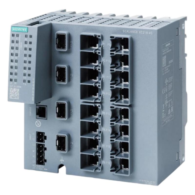
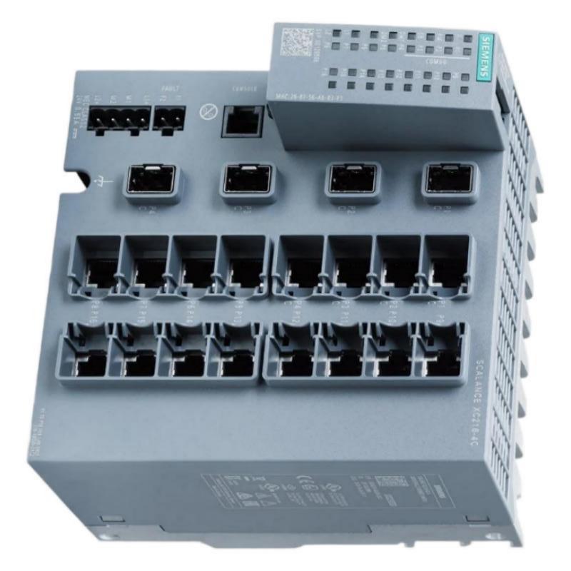
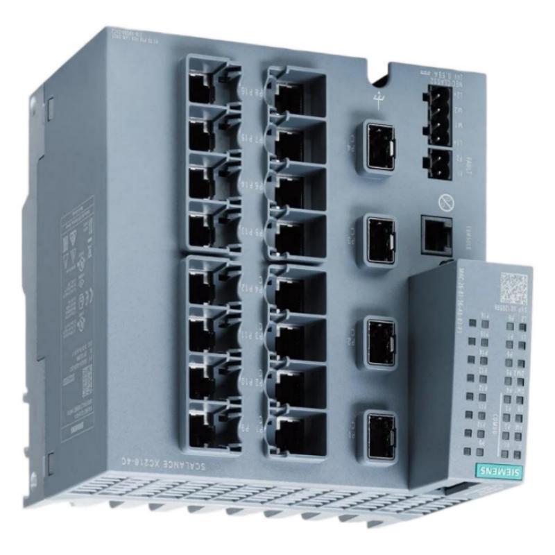
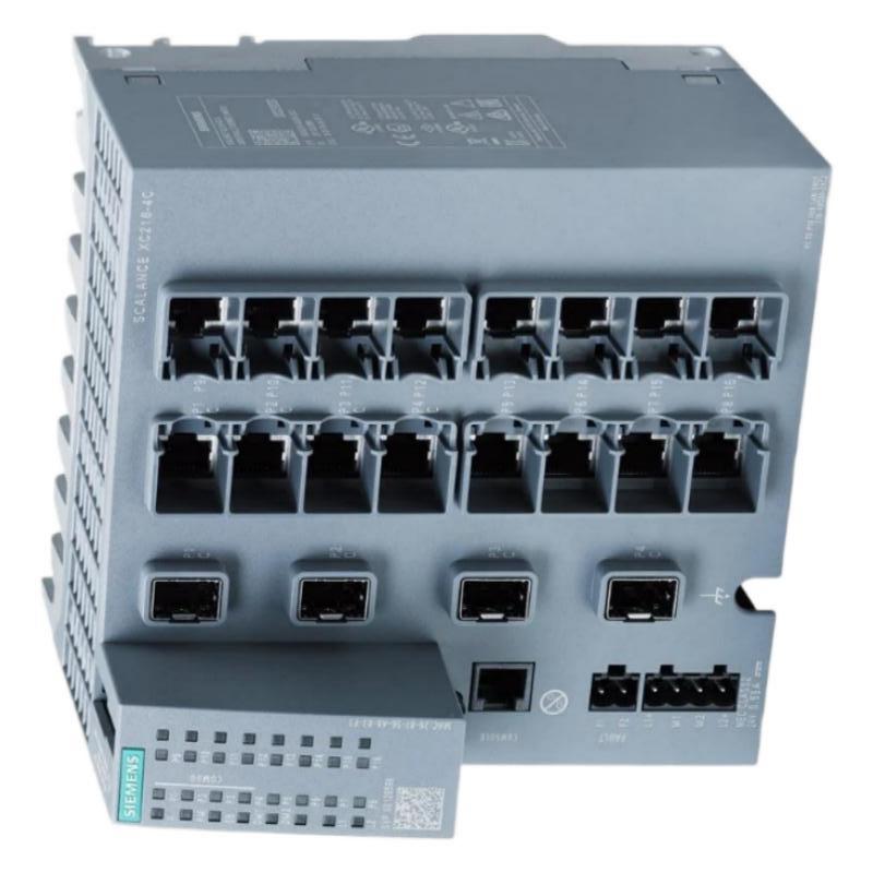
- Siemens
- 6AG1216-4BS00-7AC2
- Manageable Internet Explorer Switch
- Germany
- 140 × 150 × 125 mm
- 1.2 kg
- Xiamen, China
- New & In Stock
- T/T, PayPal, Western Union
- 1 Year
- 1-3 Working Days
- DHL, UPS, TNT, FedEx and EMS.
- 24-Hour Service
- COO
- 4
Our advantage

Global Logistics
We have a 10-year logistics and express cooperation agreement, so our products can be shipped to any place in the world.

Brand new and original
Our products are imported in bulk from the place of origin. Because of the cooperative relationship, our products are all original and 100% new.

24-hour service
We provide 7*24 hours service to our customers. We will be there whenever you need us.

Price advantage
All our products are priced very favorably because we have our own warehouse and supply.
| Company Information | |||
| [email protected] | |||
| Mobile | +8615980777398 | ||
| +8615980777398 | |||
| 15980777398 |
Product Overview
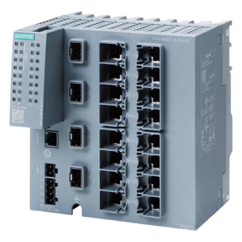
The Siemens 6AG1216-4BS00-7AC2 is identified in the supplied product information as a manageable switch for industrial network applications. Managed Ethernet switches are used to connect automation devices, organize industrial communications, and provide network-management functions that help engineers monitor and maintain communication infrastructure.
In modern industrial automation, reliable data exchange is essential for coordinating controllers, operator interfaces, engineering workstations, distributed I/O systems, and other network-connected equipment. An industrial Ethernet switch provides the physical network connections required for communication between devices. A manageable switch can also offer configuration and diagnostic functions, depending on the exact hardware and firmware.
The supplied product description, “Manageable Internet Explorer Switch,” should be verified against the full Siemens order number and device nameplate. “Internet Explorer” may be an incorrect or legacy description rather than the formal product category. For technical selection and procurement, the exact switch family, supported protocols, port configuration, and management features must be confirmed before the device is integrated into a network.
The supplied physical dimensions are 140 × 150 × 125 mm, and the listed weight is approximately 1.2 kg. These values are useful for enclosure planning, equipment inventory, and replacement logistics.
Technical Specifications
| Parameter | Specification |
|---|---|
| Manufacturer | Siemens |
| Model / Order Number | 6AG1216-4BS00-7AC2 |
| Product Description | Manageable switch, as supplied; formal catalog description to be verified |
| Product Category | Industrial network switch, subject to confirmation |
| Primary Function | Ethernet connectivity and network management, if supported by the exact device |
| Network Role | Connects compatible networked automation devices |
| Management Features | Verify supported configuration and diagnostic functions |
| Ethernet Ports | Confirm the exact port count and connector type |
| Supported Data Rates | Verify from the device specification |
| Network Protocols | Confirm supported protocols for the exact hardware |
| Power Requirements | Verify from the product label |
| Installation | Industrial cabinet or specified mounting arrangement |
| Dimensions | 140 × 150 × 125 mm |
| Weight | 1.2 kg |
| Typical Applications | Industrial communication infrastructure, subject to model verification |
Product identification note: The order number and the supplied product name should be checked against the device label before using this article for hardware selection. Port count, Ethernet speed, redundancy functions, environmental ratings, and management capabilities should not be inferred from the model number alone.
What Is a Manageable Industrial Ethernet Switch?
An industrial Ethernet switch connects multiple network devices so that data can be transferred between them over an Ethernet network. In an automation environment, these devices may include PLCs, HMIs, engineering computers, distributed I/O stations, and other compatible industrial equipment.
A basic unmanaged switch generally forwards network traffic without requiring extensive user configuration. A managed switch can provide additional control over network operation. Depending on the model, management functions may include port configuration, network diagnostics, traffic monitoring, virtual LAN configuration, redundancy support, and access controls.
These functions can help engineers organize network traffic and diagnose communication issues. However, the features available on a particular device depend on its hardware, firmware, and product family.
For the Siemens 6AG1216-4BS00-7AC2, the exact switch category and management functions should be confirmed before relying on any specific feature in a network design.
Function and Working Principle
1. Ethernet Device Connectivity
A switch provides Ethernet connections for compatible network devices. Each connected device communicates through its assigned port, allowing data to travel between devices on the same network or through the wider network infrastructure.
The number and type of available ports must be confirmed for the exact switch before planning the network layout.
2. Frame Forwarding
An Ethernet switch receives network frames and forwards them toward the appropriate destination port based on its switching logic. This allows multiple devices to exchange data without requiring each device to be connected directly to every other device.
Efficient forwarding helps support communication between controllers, operator stations, and other automation equipment.
3. Network Management
A managed switch may provide a configuration interface through which an authorized engineer can inspect network status and adjust supported settings.
Depending on the exact model, management features may include port status monitoring, diagnostics, traffic controls, or network segmentation. These features must be verified before they are included in a system design.
4. Network Diagnostics
Network diagnostics help maintenance personnel identify problems such as disconnected cables, inactive ports, communication interruptions, or incorrect configuration.
A managed switch may provide indicators or diagnostic information that helps narrow the source of a network fault. The available diagnostic tools depend on the hardware and software version.
5. Integration with Industrial Automation
When the switch is compatible with the network architecture, it can connect controllers, operator interfaces, and other industrial devices within a shared Ethernet infrastructure.
A simplified communication path is:
PLC / Controller → Industrial Ethernet Switch → HMI / Engineering Station / Networked Devices
The actual network topology depends on the system design, supported protocols, and communication requirements.
Role in Industrial Automation Systems
An industrial Ethernet switch provides network connectivity between automation devices. In systems with suitable management functions, it can also assist with network organization, monitoring, and troubleshooting.
Potential roles include:
- Connecting compatible industrial Ethernet devices.
- Providing communication paths between controllers and operator interfaces.
- Supporting engineering access to networked automation equipment.
- Organizing devices into a structured network topology.
- Helping maintenance staff identify port and connectivity issues.
- Supporting network segmentation when the hardware provides the required functions.
- Contributing to communication infrastructure for production systems.
For example, a production cell may contain a controller, an HMI, an engineering workstation, and several network-connected devices. An appropriately selected Ethernet switch can provide the required connections and simplify the physical network arrangement.
The switch does not replace the controller’s application logic. Instead, it provides communication infrastructure that allows compatible devices to exchange data.
Industrial Applications
Manufacturing Automation
Production lines often contain multiple controllers, operator interfaces, engineering stations, and other networked devices. An industrial Ethernet switch can provide the connections required for communication within a machine or production cell.
Process Control Systems
Process facilities may use Ethernet networks to connect control equipment, operator stations, and supporting systems. The switch must be selected according to the required network architecture and environmental conditions.
Machine-Building Applications
Machine builders frequently integrate controllers, HMIs, remote I/O, and diagnostic devices into compact network layouts. A suitable switch can help organize these connections and simplify machine integration.
Packaging and Material Handling
Packaging lines and material-handling systems may require communication between several control devices and operator stations. Ethernet switching can support this communication when the connected equipment uses compatible networking.
Industrial Monitoring
Network-connected monitoring systems can use Ethernet to exchange status information between equipment and supervisory applications. Managed switching features, when available, can assist with connectivity monitoring and fault diagnosis.
Control Cabinets and Distributed Equipment
Industrial cabinets may contain several Ethernet-enabled devices that need a common network connection. A switch can provide local connectivity while linking the cabinet to a wider industrial network.
Installation and Network Integration
Correct installation and configuration are essential for reliable communication and long-term maintainability.
Verify the Product Identity
Confirm the complete order number 6AG1216-4BS00-7AC2 and the formal product description on the device label. Verify whether the unit is an industrial Ethernet switch and determine its exact family, port configuration, and management capabilities.
Do not assume that a product described as an “Internet Explorer Switch” is a particular Siemens switch model without checking its identification.
Plan the Network Topology
Determine which devices require connectivity and how they should be connected. Consider the number of ports, cable routes, network segmentation requirements, and any required connections to other network segments.
The topology should be designed around the actual device capabilities rather than assumptions based on a generic switch description.
Confirm Power Requirements
Check the required supply voltage, polarity, current demand, and terminal assignments against the device label and applicable documentation.
Provide appropriate circuit protection and ensure that the power supply can support the switch and other equipment connected to the same supply.
Connect Ethernet Cables
Use cables and connectors appropriate for the confirmed Ethernet interfaces and installation environment. Inspect cable condition, connector seating, and routing before commissioning.
Avoid placing communication cables where they may be damaged by mechanical movement, sharp edges, excessive bending, or environmental contamination.
Configure Management Functions
If the verified device supports management, configure only the functions required by the network design. Depending on the actual model, these may include port settings, network addressing, monitoring, or traffic-management options.
Record the configuration and ensure that access is limited to authorized personnel.
Test Network Communication
After installation, verify that each connected device can communicate as intended. Check port indicators and available diagnostic information, and confirm that the network remains stable during normal operation.
Where applicable, test recovery behavior after a cable disconnection or power interruption. Any redundancy or recovery behavior must be validated against the actual hardware capabilities.
Network Configuration and Security Considerations
Use a Documented IP Addressing Plan
Where the switch provides a management IP address, record it in the network documentation. Avoid conflicting addresses and ensure that the management network is consistent with the site’s addressing plan.
Restrict Administrative Access
If the device supports user authentication or management access controls, use them to restrict configuration changes to authorized personnel. Replace default credentials where applicable and follow the site’s security policies.
Separate Network Traffic Where Supported
Some managed switches support network segmentation or traffic controls. These functions can help separate traffic between different systems, but their availability and configuration limits must be verified for the specific model.
Maintain Configuration Backups
Keep a record of the switch configuration, firmware information, port assignments, and network connections. A documented configuration can reduce restoration time following replacement or maintenance.
Verify Firmware Compatibility
Before changing firmware, confirm that the update is intended for the exact hardware version and follows the applicable installation procedure. An incompatible update can disrupt network operation.
Follow Industrial Cybersecurity Practices
Place network equipment within an appropriately protected industrial network architecture. Limit unnecessary access, maintain asset records, and coordinate configuration changes with the site’s network and automation teams.
Troubleshooting the Siemens 6AG1216-4BS00-7AC2
Troubleshooting should begin with product identification, power, cabling, connected devices, and network configuration.
The Switch Does Not Power On
Possible causes include an incorrect supply, loose terminals, an open protective device, or a hardware fault.
Recommended checks:
- Verify the required supply against the product label.
- Inspect the power wiring and terminal connections.
- Check the associated circuit protection.
- Confirm that the supply is stable.
- Inspect the enclosure and device for signs of overheating or damage.
Isolate power before handling exposed electrical connections.
No Ethernet Link
If a connected device does not establish a link, check the Ethernet cable, connector seating, port status, and connected device.
Where possible, test with a known-good cable and verify that the device on the other end is powered and using a compatible interface.
Communication Is Intermittent
Intermittent communication may be caused by damaged cables, loose connectors, electrical interference, unstable power, or configuration problems.
Inspect cable routes and connectors, review available diagnostics, and determine whether the problem affects one port or several network devices.
A Device Cannot Be Reached
If a connected device cannot communicate with another network device, check the addressing plan, subnet configuration, routing arrangements, and any applicable traffic controls.
Do not assume that a failed connection indicates a switch hardware fault until the network configuration and endpoint devices have been checked.
Network Performance Is Poor
Potential causes include excessive traffic, unsuitable topology, incorrect configuration, damaged cabling, or a limitation of the connected equipment.
Review network utilization and the requirements of the connected devices. Any changes to network settings should be tested to avoid interrupting production communication.
Management Access Is Unavailable
If the device is confirmed to support management but its configuration interface cannot be reached, verify the management address, physical connection, network path, access permissions, and configuration method supported by the hardware.
The available management method must be established from the exact product documentation.
Maintenance Recommendations
Regular inspection helps maintain reliable industrial network operation.
Inspect Ethernet cabling. Check for damaged insulation, loose connectors, excessive bending, and mechanical wear.
Check power connections. Confirm that terminals remain secure and that the supply meets the device requirements.
Review network indicators. Investigate unexpected link loss, repeated port changes, or other abnormal indications.
Maintain configuration records. Keep port assignments, network addressing information, and approved settings documented.
Control the installation environment. Protect the device from excessive dust, moisture, heat, and vibration according to its rated conditions.
Back up supported configurations. If the device provides configuration backup functionality, maintain a verified copy using the supported method.
Document firmware changes. Record the installed firmware version and any approved updates.
Review recurring communication faults. Repeated disconnections should be investigated systematically rather than resolved only through repeated restarts.
Compatible System Components
An industrial Ethernet switch may operate as part of a network containing several categories of automation and IT equipment. Compatibility depends on the verified switch interfaces, supported protocols, and network architecture.
| Component Category | Typical Function |
|---|---|
| PLC or Industrial Controller | Executes machine or process control logic |
| HMI Panel | Provides operator interaction and status displays |
| Engineering Workstation | Supports programming, configuration, and diagnostics |
| Remote I/O Device | Exchanges field signals with the control system |
| Industrial Ethernet Cable | Carries network traffic between devices |
| Ethernet Network Adapter | Provides network connectivity to compatible equipment |
| SCADA or Monitoring System | Collects and displays process information |
| Industrial Firewall or Router | Provides network boundary or routing functions where required |
| Control Cabinet | Houses network and automation equipment |
| Network Documentation | Records topology, addresses, and configuration details |
Specific Siemens controllers, network adapters, or expansion devices should not be assumed to be compatible solely because they belong to the same broad product portfolio. Confirm interface requirements and supported network functions before integration.
Replacement and Procurement Considerations
When purchasing or replacing the Siemens 6AG1216-4BS00-7AC2, verify the exact order number and formal product description.
Important checks include:
- Full order number and device label.
- Confirmed product family and switch category.
- Number and type of Ethernet ports.
- Supported data rates and network protocols.
- Management and diagnostic capabilities.
- Power supply requirements.
- Mounting and environmental specifications.
- Firmware and configuration compatibility.
- Network topology and operational requirements.
The supplied dimensions are 140 × 150 × 125 mm, and the supplied weight is 1.2 kg. These values support panel-layout planning, inventory management, and shipping preparation but do not establish functional interchangeability.
If an alternative switch is considered, compare port count, supported network features, environmental ratings, power requirements, mounting arrangement, and configuration compatibility before installation.
Key Advantages
Centralized Network Connectivity
An industrial Ethernet switch can provide a structured connection point for compatible networked automation devices.
Network Organization
Where management features are available, the switch may help engineers organize network connections and monitor communication status.
Support for Distributed Automation
Ethernet switching allows controllers, operator interfaces, and other compatible devices to exchange data through a common network infrastructure.
Easier Troubleshooting
Port indicators and supported diagnostics can help maintenance personnel identify disconnected cables, inactive ports, and certain network problems.
Practical Control-Panel Integration
The supplied dimensions of 140 × 150 × 125 mm help engineers evaluate the physical space required for installation.
Improved Network Maintainability
Documented port assignments, configuration records, and structured network design can simplify replacement and fault recovery.
Technical FAQs
What is the Siemens 6AG1216-4BS00-7AC2?
It is a Siemens product identified by order number 6AG1216-4BS00-7AC2. The supplied description identifies it as a manageable switch, but the exact catalog classification should be verified before technical selection.
What does a manageable switch do?
A managed Ethernet switch connects network devices and may provide additional configuration, monitoring, and diagnostic functions. The available features depend on the specific model.
What are the dimensions of the product?
The supplied dimensions are 140 × 150 × 125 mm.
How much does the product weigh?
The supplied weight is approximately 1.2 kg.
Can the switch connect PLCs and HMIs?
An industrial Ethernet switch can connect PLCs, HMIs, and other networked devices when their interfaces and communication requirements are compatible with the switch.
Does this model support network redundancy?
Redundancy support must be verified against the exact product specification. Do not assume that every managed switch supports the same recovery or redundancy functions.
What should be checked before installation?
Confirm the full order number, product category, port configuration, data rates, power requirements, supported network functions, mounting requirements, and environmental ratings.
What causes industrial Ethernet communication faults?
Possible causes include damaged cables, loose connectors, incorrect addressing, unsuitable configuration, unstable power, electrical interference, or a fault in a connected device.
Is this switch interchangeable with another Siemens model?
Not automatically. The port configuration, supported protocols, management features, power requirements, mounting arrangement, and environmental specifications must be compared before replacement.
Conclusion
The Siemens 6AG1216-4BS00-7AC2 Manageable Switch, as described in the supplied product information, is intended for consideration in industrial network applications requiring Ethernet connectivity and potentially managed network functions. Its exact product category and supported features should be verified before it is specified for a production system.
With supplied dimensions of 140 × 150 × 125 mm and a weight of 1.2 kg, the device can be evaluated for industrial cabinet layouts, inventory planning, and replacement logistics.
Reliable integration depends on confirming the complete product identity, checking the available network interfaces and electrical requirements, configuring supported management functions correctly, and testing communication with all connected equipment. Accurate identification and systematic commissioning are essential for maintaining dependable industrial network performance.