

ProductPRODUCT
Featured products
Contact Us
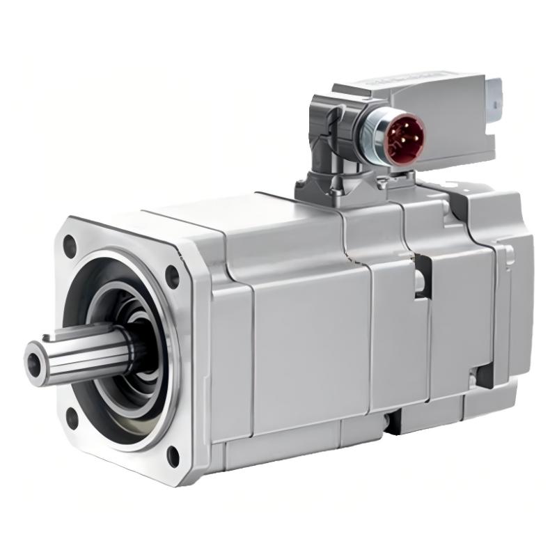
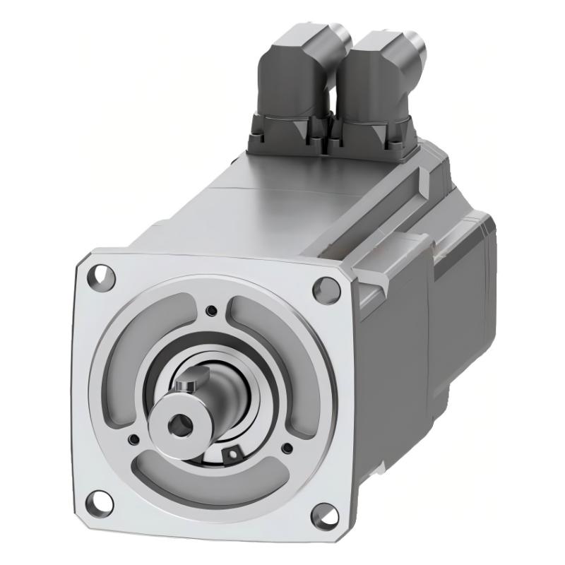
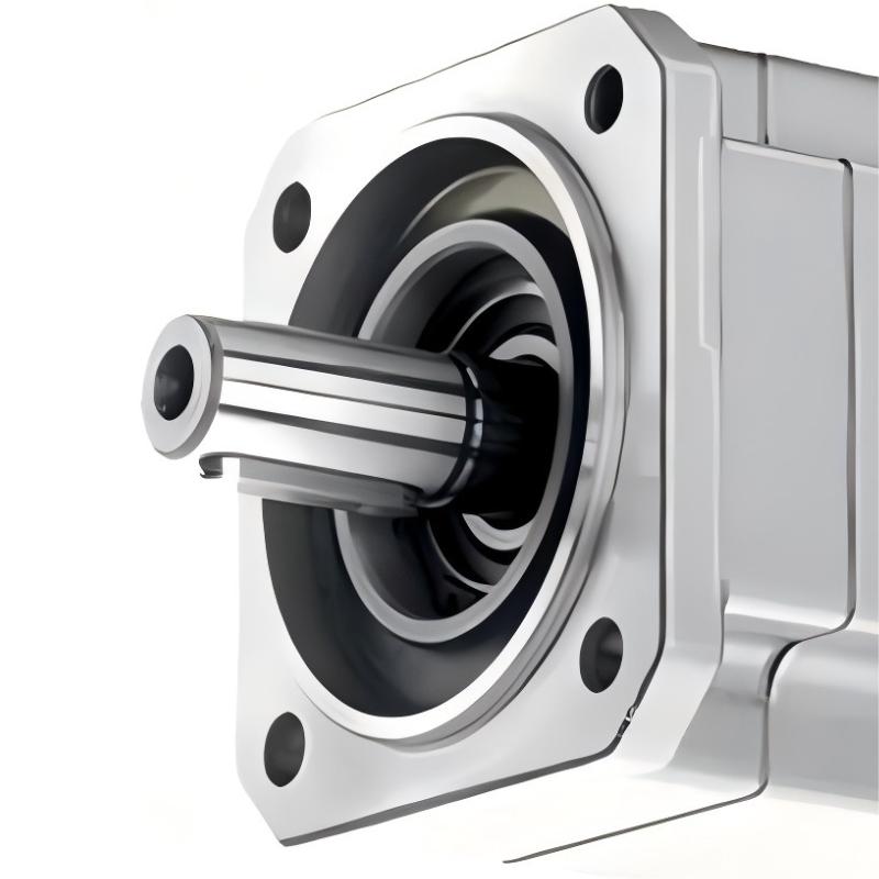
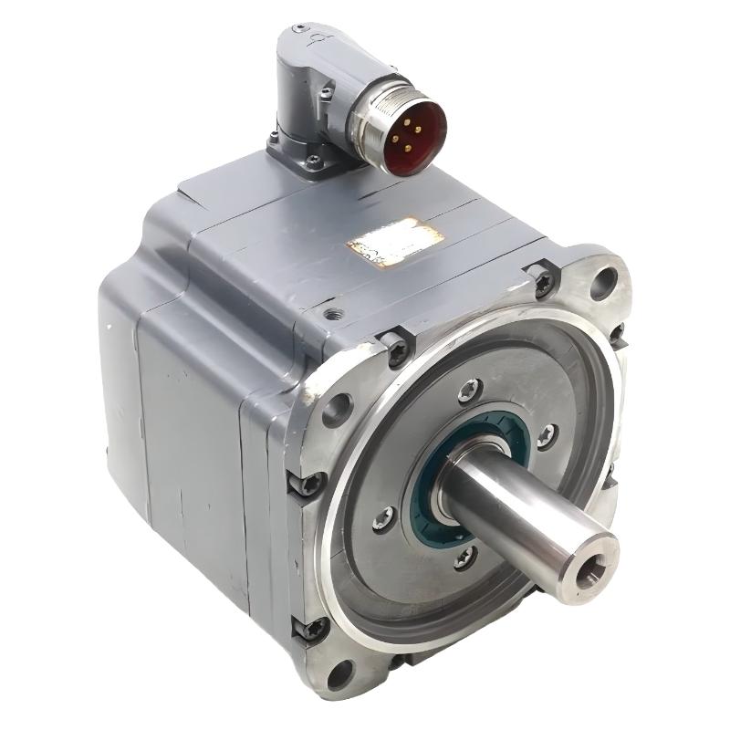
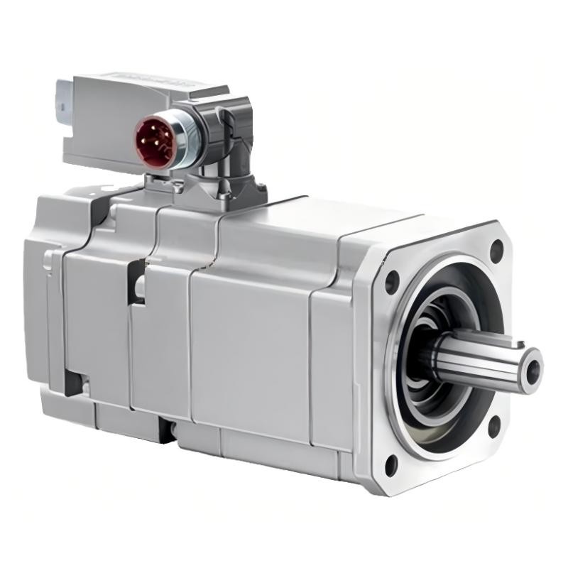
- Siemens
- 1FK7101-2AF71-1UA0
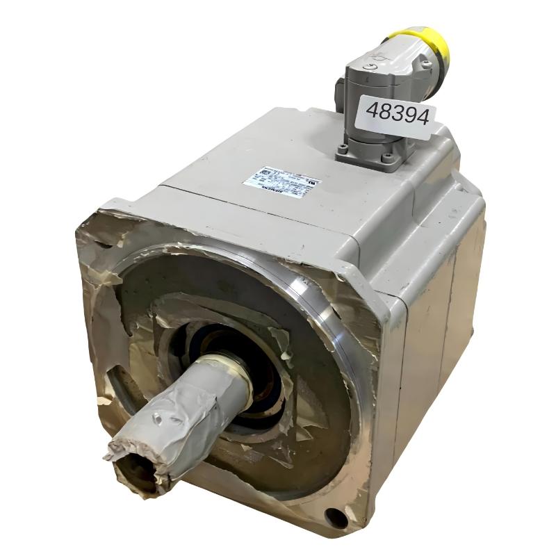
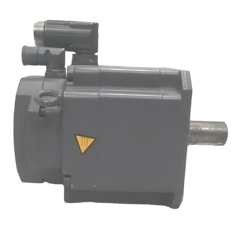
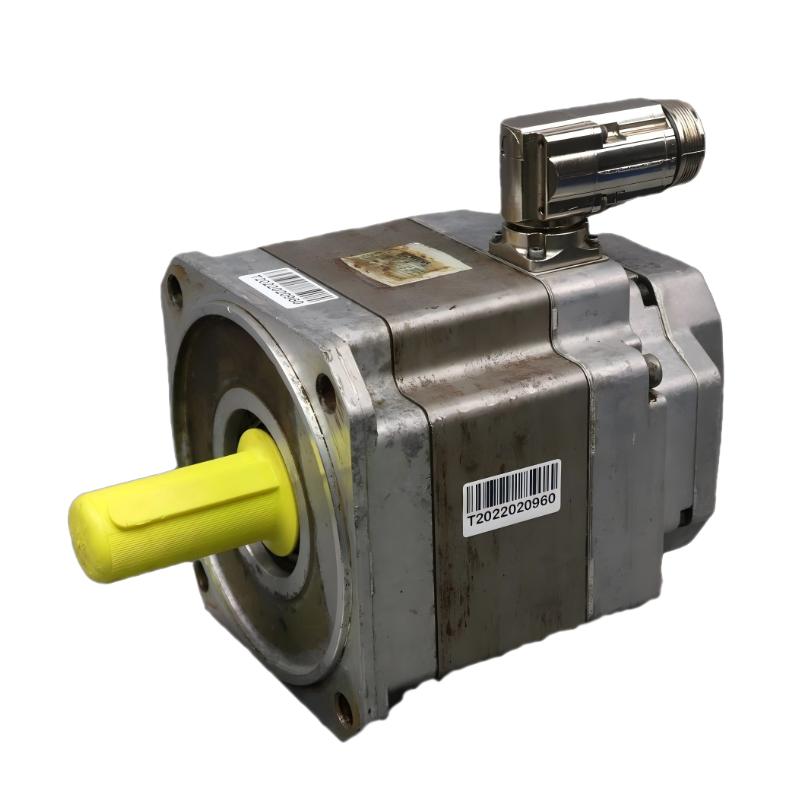
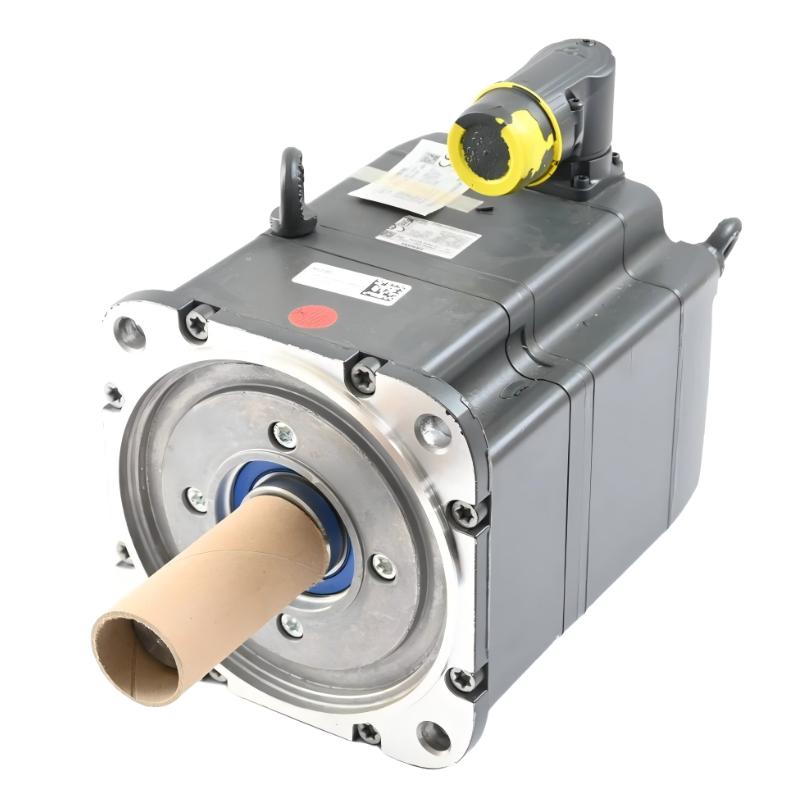
- SIMOTICS S Synchronous Motor
- Germany
- 300 mm x 200 mm x 150 mm
- 23kg
- Xiamen, China
- New & In Stock
- T/T, PayPal, Western Union
- 1 Year
- 1-3 Working Days
- DHL, UPS, TNT, FedEx and EMS.
- 24-Hour Service
- COO
- 6
Our advantage

Global Logistics
We have a 10-year logistics and express cooperation agreement, so our products can be shipped to any place in the world.

Brand new and original
Our products are imported in bulk from the place of origin. Because of the cooperative relationship, our products are all original and 100% new.

24-hour service
We provide 7*24 hours service to our customers. We will be there whenever you need us.

Price advantage
All our products are priced very favorably because we have our own warehouse and supply.
| Company Information | |||
| [email protected] | |||
| Mobile | +8615980777398 | ||
| +8615980777398 | |||
| 15980777398 |
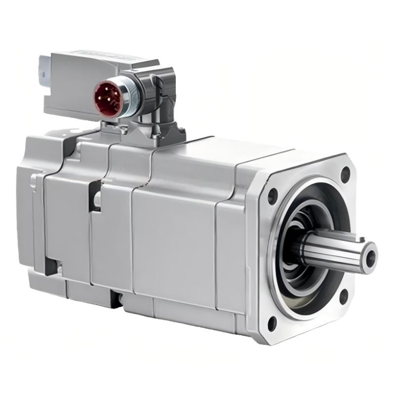
Siemens 1FK7101-2AF71-1UA0 Servo Motor: Technical Specifications, Product Description, Applications and Advantages
1. Product Overview
The Siemens 1FK7101-2AF71-1UA0 is a synchronous servo motor in the SIMOTICS S product family and the 1FK7 series. It is designed for industrial automation applications that require controlled movement, accurate speed regulation, repeatable positioning and dependable torque output.
This motor is intended to operate as part of a complete servo system, working with a compatible servo drive, feedback connection and machine controller. It can support applications involving repeated acceleration and deceleration, coordinated movement, controlled rotation and positioning tasks.
The model designation identifies a specific motor configuration. Details such as feedback type, shaft design, brake arrangement, protection rating and connector configuration are important when selecting a replacement. Motors that share the same basic series may not be electrically or mechanically interchangeable.
The 1FK7101-2AF71-1UA0 is associated with a resolver-based feedback configuration, a keyed shaft and natural cooling. It does not have an integrated holding brake. These characteristics should be considered when evaluating its suitability for an existing machine or a new automation project.
Important technical note: Exact ratings and mechanical dimensions should be confirmed against the motor nameplate and the technical drawing for the complete order number. The tables below distinguish typical motor-family values from details that require configuration-specific confirmation.
2. Brand and Product Series
| Item | Description |
|---|---|
| Brand | Siemens |
| Product family | SIMOTICS S |
| Product series | 1FK7 |
| Model number | 1FK7101-2AF71-1UA0 |
| Motor type | Permanent-magnet synchronous servo motor |
| Main function | Controlled speed, torque and position |
| Cooling method | Natural cooling |
| Mounting arrangement | Flange-mounted; verify exact mounting drawing |
| Shaft configuration | Keyed shaft |
| Feedback system | Resolver-based configuration; verify exact interface |
| Holding brake | No integrated holding brake |
| Protection rating | Confirm exact order-specific rating |
| Typical application | Industrial machinery and motion-control systems |
About the SIMOTICS S 1FK7 Series
The SIMOTICS S 1FK7 family is designed for servo applications in which controlled motion and repeatability are more important than simple constant-speed operation. It is used in a broad range of industrial machinery, including machine tools, packaging equipment, automated assembly systems and material-handling mechanisms.
A servo motor differs from a conventional fixed-speed motor because its operation is coordinated with a drive and feedback system. The drive regulates the motor’s current and motion according to commands from the controller. Feedback allows the system to monitor movement and adjust its response.
The exact configuration matters. A motor with a resolver is not automatically a direct replacement for one equipped with an absolute encoder. The feedback interface, shaft dimensions, brake configuration, winding data and drive parameters all need to match the application.
3. Detailed Technical Parameters
The following table summarizes the principal technical characteristics of the 1FK7101-2AF71-1UA0. Values such as rated torque, static torque and maximum torque refer to different operating conditions and should not be used interchangeably.
| Parameter | Specification |
|---|---|
| Model number | 1FK7101-2AF71-1UA0 |
| Brand | Siemens |
| Product family | SIMOTICS S |
| Product series | 1FK7-CT |
| Motor type | Permanent-magnet synchronous servo motor |
| Optimum operating power | 4.8 kW |
| Product power class | Approximately 4.9 kW |
| DC-link voltage class | 600 V DC |
| Rated speed | 3,000 rpm |
| Optimum operating speed | 3,000 rpm |
| Rated torque at 100 K temperature rise | 15.5 Nm |
| Static torque at 60 K temperature rise | 22.5 Nm |
| Static torque at 100 K temperature rise | 27 Nm |
| Maximum motor torque | 80 Nm |
| Rated current | 11.6 A |
| Stall current at 60 K temperature rise | 15.2 A |
| Stall current at 100 K temperature rise | 18.8 A |
| Maximum current | 63 A |
| Number of poles | 8 |
| Maximum permissible mechanical speed | 5,000 rpm |
| Maximum permissible inverter speed | 5,000 rpm |
| Torque constant | Approximately 1.44 Nm/A |
| Voltage constant at 20°C | 92.5 V per 1,000 rpm |
| Winding resistance at 20°C | Approximately 0.14 Ω |
| Rotating-field inductance | 3.5 mH |
| Electrical time constant | 25 ms |
| Mechanical time constant | 1.62 ms |
| Thermal time constant | 60 min |
| Rotor moment of inertia | 79 kg·cm² |
| Efficiency | Approximately 93% |
| Shaft torsional stiffness | 164,000 Nm/rad |
| Cooling method | Natural cooling |
| Mounting arrangement | IM B5; IM V1 and IM V3 mounting arrangements where permitted |
| Frame / shaft height | 100 mm |
| Flange | Flange size 1 |
| Power connector | Rotatable |
| Feedback system | Multi-pole resolver |
| Feedback interface | DRIVE-CLiQ |
| Resolver resolution | 15-bit resolver system; verify drive-specific interpretation |
| Shaft design | Keyed shaft / feather key |
| Holding brake | No integrated holding brake |
| Degree of protection | IP64 |
| Temperature monitoring | Pt1000 temperature sensor |
| Radial runout tolerance | 0.050 mm |
| Concentricity tolerance | 0.10 mm |
| Axial runout tolerance | 0.10 mm |
| Vibration severity | Grade A |
| Approximate net weight | 23.0 kg |
| Overall dimensions | Confirm from the exact mechanical drawing; frame height alone does not define the complete envelope |
| Drive compatibility | Compatible servo drive with support for the specified motor and resolver interface |
3.1 Power and Torque
The motor has an optimum operating power of 4.8 kW at 3,000 rpm. This figure represents its specified operating point rather than a guarantee of identical output under every load condition.
The rated torque of 15.5 Nm at a 100 K temperature rise is an important reference for evaluating continuous operation. The static torque rating of 27 Nm at a 100 K temperature rise describes a different operating condition and should not be treated as the continuous running torque.
The maximum torque rating of 80 Nm indicates the motor’s specified upper torque capability under applicable conditions. The duration for which high torque can be produced depends on the motor’s thermal limits, drive current capability, operating speed and duty cycle.
3.2 Speed and Current
The rated speed is 3,000 rpm, while the specified maximum permissible speed is 5,000 rpm. Operating near the maximum speed requires checking the drive’s operating envelope, load torque, coupling limits and mechanical safety requirements.
The rated current is 11.6 A. The maximum current rating of 63 A is a limiting value, not a continuous current recommendation. The selected drive must provide suitable current control and overload capability for the intended application.
3.3 Feedback and Position Control
The model uses a multi-pole resolver with a DRIVE-CLiQ interface. This feedback configuration provides rotor-position information for the servo drive.
A resolver-based motor should not be assumed to be interchangeable with a motor that uses a single-turn or multi-turn absolute encoder. Even when the motors share similar power, torque and mounting dimensions, feedback compatibility and commissioning requirements can differ.
3.4 Dimensions and Weight
The motor has a shaft height of 100 mm and an approximate net weight of 23.0 kg. These figures are useful for initial machine-layout planning and handling estimates.
The complete overall dimensions should be obtained from the mechanical drawing for the exact order number. In particular, confirm the flange pattern, shaft diameter, shaft extension, keyway, motor housing length and connector clearance before designing a mounting bracket or ordering a replacement.
4. Product Introduction
The Siemens 1FK7101-2AF71-1UA0 is designed for industrial motion systems that need accurate, repeatable and controllable mechanical movement. Typical operating tasks include moving a machine axis to a specified position, maintaining a commanded speed, accelerating a load, slowing down smoothly and coordinating motion with other equipment.
The motor uses a permanent-magnet synchronous design. When the servo drive supplies controlled current to the motor windings, the interaction between the magnetic field and the rotor produces torque. The drive adjusts the current and motor movement according to commands from the machine controller.
Feedback is an essential part of this process. The resolver provides rotor-position information so the drive can control motor operation. When the feedback hardware, drive parameters and mechanical load are properly matched, the system can deliver stable speed regulation and repeatable positioning.
The keyed shaft supports a mechanical connection designed for a matching keyway and coupling. This is useful in equipment where torque must be transmitted through a positive mechanical connection. Shaft alignment, coupling fit and permissible radial and axial loads must be considered during installation.
The motor uses natural cooling, avoiding the need for a separate liquid-cooling circuit as part of its basic configuration. Adequate heat dissipation is still necessary, especially in enclosed machines or applications involving frequent acceleration, high torque or extended operating periods.
The UA0 configuration does not include an integrated holding brake. If the driven mechanism must remain stationary when the drive is disabled, the machine designer should determine whether a separate holding brake or another mechanical restraint is needed.
In practical terms, this motor is best evaluated as part of a complete motion-control system. Motor performance depends not only on its nominal ratings, but also on the selected drive, feedback wiring, control parameters, transmission, load inertia and duty cycle.
5. Product Applications
5.1 CNC Machine Tools
The motor may be used in suitable machine-tool feed axes, positioning mechanisms and auxiliary motion systems. Its controlled torque and feedback capability help the drive execute commanded movements and maintain repeatable operation.
For machine-tool applications, selection should take account of cutting forces, axis inertia, required positioning accuracy, acceleration time and the mechanical transmission. The motor must be sized for both continuous operating torque and peak motion demands.
5.2 Packaging Machinery
Packaging equipment often requires repeated feeding, indexing, cutting, sealing and product-transfer movements. A servo motor can coordinate these operations with the production sequence and support consistent cycle timing.
The 1FK7101-2AF71-1UA0 may be suitable where its speed and torque characteristics meet the machine’s requirements. Frequent starts and stops should be included in the duty-cycle assessment, since repeated acceleration can create significant peak-current and thermal demands.
5.3 Automated Assembly Equipment
Assembly systems commonly move components between stations, align parts and perform repeatable positioning operations. A correctly configured servo system can help control movement, reduce inconsistent stopping behavior and coordinate several machine axes.
The motor’s resolver feedback can be useful in a control architecture designed for that feedback type. Compatibility with the existing drive and controller should be established before selecting it for a retrofit.
5.4 Material Handling and Transfer Systems
Automated transfer mechanisms use servo motors to position workpieces, move fixtures and operate horizontal slides. The motor’s torque and speed characteristics may suit such applications when the load inertia and required motion profile are within the permitted operating envelope.
Because this configuration does not include an integrated holding brake, gravity-loaded axes require particular attention. If the mechanism could move when power is removed, the machine may need a separate brake or other appropriate holding mechanism.
5.5 Printing and Converting Machinery
Printing, paper-processing and converting systems may use servo motors for feed rollers, indexing mechanisms and synchronized movement. Controlled speed and positioning can help maintain repeatable material handling and coordinated production cycles.
The suitability of this model depends on the required continuous torque, acceleration profile, operating speed and feedback architecture. The drive must also be able to handle the load’s inertia and dynamic demands.
5.6 Special-Purpose Industrial Machinery
Special-purpose machines frequently combine several mechanical functions, such as positioning, feeding, rotating and transferring parts. A servo motor can be used where a controller must coordinate these movements with a defined sequence.
The 1FK7101-2AF71-1UA0 is a candidate for such applications when its motor data, resolver interface and mechanical configuration match the machine design.
6. Product Advantages
6.1 Accurate Motion Control
The motor is designed for use with a servo drive that regulates torque, speed and position. This makes it suitable for machinery requiring controlled acceleration, repeatable movements and predictable response to commands.
6.2 Resolver-Based Feedback
The resolver configuration is useful in systems designed around resolver feedback. When replacing an existing motor, retaining the same feedback architecture can simplify integration, provided the drive and wiring remain compatible.
6.3 Useful Rated and Static Torque
The motor’s rated torque of 15.5 Nm and static torque of 27 Nm at a 100 K temperature rise provide useful reference points for machine sizing. Its maximum torque rating supports higher short-duration demands within the specified operating limits.
6.4 High-Speed Capability
The 3,000 rpm rated speed and 5,000 rpm maximum permissible speed provide flexibility for applications with different operating-speed requirements. The actual usable speed depends on load torque, the drive’s current and voltage limits, and the machine’s mechanical constraints.
6.5 Keyed Shaft Connection
The keyed shaft can provide a positive torque-transmission connection with a correctly matched coupling. Proper keyway dimensions, shaft fit and alignment help reduce unwanted mechanical stress and wear.
6.6 Natural Cooling
Natural cooling avoids the need for a dedicated liquid-cooling circuit. It can simplify the machine’s cooling arrangement, provided the installation allows sufficient heat dissipation and the motor operates within its thermal limits.
6.7 Flange-Mounted Construction
The flange-mounted design allows installation on compatible machine frames and mechanical assemblies. Correct alignment and verification of the flange dimensions are important for reducing vibration and excessive bearing loads.
6.8 Compatibility with a Servo-Control Architecture
The resolver and DRIVE-CLiQ configuration can support integration into compatible motion-control systems. Correct motor identification, feedback setup and drive parameterization are essential for reliable operation.
6.9 Suitable for Repetitive Industrial Motion
The motor can support repeated movement and coordinated operation in automated equipment. The quality of the resulting motion depends on the complete system, including the mechanical transmission, drive tuning, feedback configuration and load profile.
6.10 Straightforward Brake Configuration for Non-Braked Applications
For applications that do not require a motor-integrated holding brake, this configuration avoids that feature. If the load must be held while power is off, a separate holding arrangement may still be necessary.
7. Five Related Models in the Same Series
The following models provide a comparison shortlist within the 1FK7 family. Their feedback systems and shaft configurations differ, so the suffixes should be checked carefully. Where exact order-specific data are not established here, the table identifies the values that require confirmation instead of presenting them as guaranteed specifications.
| Model number | Main configuration | Power / rated speed | Torque reference | Brake / protection | Dimensions | Weight (kg) |
|---|---|---|---|---|---|---|
| 1FK7101-2AF71-1UA0 | Multi-pole resolver; keyed shaft | 4.8 kW / 3,000 rpm | 15.5 Nm rated; 27 Nm static at 100 K | No brake; IP64 | Exact drawing required | Approx. 23.0 |
| 1FK7101-2AF71-1RA0 | 20-bit + 12-bit multi-turn absolute encoder; keyed shaft | 4.8 kW / 3,000 rpm | 15.5 Nm rated; 27 Nm static at 100 K | No brake; IP64 | Exact drawing required | Approx. 23.0 |
| 1FK7101-2AF71-1QA0 | 20-bit single-turn absolute encoder; keyed shaft | 4.8 kW / 3,000 rpm | 15.5 Nm rated; 27 Nm static at 100 K | No brake; IP64 | Exact drawing required | Approx. 23.0 |
| 1FK7101-2AF71-1RG0 | 20-bit + 12-bit multi-turn absolute encoder; smooth shaft | 4.8 kW / 3,000 rpm | 15.5 Nm rated; 27 Nm static at 100 K | No brake; IP64 | Exact drawing required | Approx. 23.0 |
| 1FK7101-2AF71-1DG0 | 22-bit incremental encoder; smooth shaft | 4.8 kW / 3,000 rpm | 15.5 Nm rated; 27 Nm static at 100 K | No brake; IP64 | Exact drawing required | Approx. 23.0 |
7.1 1FK7101-2AF71-1UA0
This is the reference model. It is the appropriate starting point when the existing machine uses a multi-pole resolver and keyed shaft. Retaining the same configuration can reduce changes during replacement, although the drive and wiring must still be checked.
7.2 1FK7101-2AF71-1RA0
This model uses a multi-turn absolute encoder rather than the UA0 resolver configuration. It may be appropriate where the controller requires absolute position feedback across multiple shaft rotations. It should not be considered an automatic plug-in replacement for the resolver version.
7.3 1FK7101-2AF71-1QA0
This model uses a single-turn absolute encoder. It may suit systems designed for that encoder type, but the feedback architecture and drive parameters must be compatible with the installed equipment.
7.4 1FK7101-2AF71-1RG0
This model combines multi-turn absolute feedback with a smooth shaft. It may be relevant where the mechanical coupling requires a smooth shaft rather than a keyed connection. The coupling and shaft geometry must be verified before installation.
7.5 1FK7101-2AF71-1DG0
This model uses a 22-bit incremental encoder and a smooth shaft. It may suit a control system designed for incremental feedback, but the encoder type and shaft configuration differ from the UA0.
Selection note: The models above share a similar basic motor rating, but feedback hardware and shaft design are important differences. Before ordering, confirm the complete order number, encoder or resolver type, mounting arrangement, protection rating, shaft dimensions and drive compatibility.
8. Five Other Siemens Models to Consider
The following alternatives cover related motor configurations and a smaller motor frame. They are useful starting points for a comparison, but they should not be treated as direct replacements without checking the complete order number and machine requirements.
| Model number | Product family | Power / rated speed | Torque reference | Feedback / brake | Dimensions | Weight (kg) |
|---|---|---|---|---|---|---|
| 1FK7101-2AF71-1RA0 | SIMOTICS S 1FK7-CT | 4.8 kW / 3,000 rpm | 15.5 Nm rated; 27 Nm static at 100 K | Multi-turn absolute encoder; no brake | Exact drawing required | Approx. 23.0 |
| 1FK7101-2AF71-1QA0 | SIMOTICS S 1FK7-CT | 4.8 kW / 3,000 rpm | 15.5 Nm rated; 27 Nm static at 100 K | Single-turn absolute encoder; no brake | Exact drawing required | Approx. 23.0 |
| 1FK7101-2AF71-1DG0 | SIMOTICS S 1FK7-CT | 4.8 kW / 3,000 rpm | 15.5 Nm rated; 27 Nm static at 100 K | Incremental encoder; no brake | Exact drawing required | Approx. 23.0 |
| 1FK7100-2AF71-1UA0 | SIMOTICS S 1FK7 family | Approx. 3.8 kW / 3,000 rpm | 12 Nm rated; 18 Nm static at 100 K | Resolver configuration; no brake | Exact drawing required | Approx. 17.6 |
| 1FK7083-2AC71-1 | SIMOTICS S 1FK7 family | Confirm complete order number | Confirm complete order number | Depends on suffix | Exact drawing required | Confirm exact variant |
8.1 1FK7101-2AF71-1RA0
This model retains the same basic 1FK7101 motor class but uses multi-turn absolute feedback. It may be worth considering when the control system needs absolute position tracking and supports the encoder interface.
8.2 1FK7101-2AF71-1QA0
This is an alternative for applications designed around single-turn absolute feedback. The feedback requirements should be reviewed before changing from a resolver-based system.
8.3 1FK7101-2AF71-1DG0
This variant uses an incremental encoder. It can be appropriate for systems designed around incremental position feedback, provided the controller and drive support the encoder configuration.
8.4 1FK7100-2AF71-1UA0
This model belongs to the same broad 1FK7 family but uses a smaller motor configuration. Its lower torque and power class may suit a lighter load, but it should only be selected after calculating the required continuous torque, acceleration torque and operating speed.
8.5 1FK7083-2AC71-1
This designation represents a different 1FK7 motor configuration. The complete suffix is required to establish its precise feedback, brake, shaft and electrical characteristics. It should be treated as a candidate for evaluation rather than a confirmed equivalent.
9. Installation and Commissioning Considerations
9.1 Mechanical Mounting
Check the mounting flange, bolt pattern, shaft diameter, shaft extension and keyway against the mechanical drawing. The mounting surface should be rigid, flat and properly aligned with the driven equipment.
Incorrect alignment can increase vibration and bearing loads. A coupling should be selected for the actual shaft dimensions, torque requirements and operating speed.
9.2 Electrical Connection
Use power and feedback cables compatible with the motor and servo drive. Verify connector assignments, cable ratings, grounding, shielding and routing before energizing the equipment.
The resolver and DRIVE-CLiQ interface must match the connected drive architecture. Do not assume that a motor with a different feedback system can be connected using the same wiring and parameters.
9.3 Drive Configuration
Configure the drive for the exact motor model and feedback system. Motor identification, current limits, speed limits and control parameters should be checked before commissioning.
Parameters from another motor in the same series should not be copied without validation. Similar motor frames can have different windings, encoder systems and operating limits.
9.4 Holding and Safety Requirements
The 1FK7101-2AF71-1UA0 has no integrated holding brake. If the driven mechanism must remain stationary when power is removed, determine whether a separate brake or another suitable mechanical restraint is necessary.
This is particularly important for vertical axes or gravity-loaded mechanisms. Servo torque alone should not be relied on as a mechanical safety restraint when the drive is disabled.
9.5 Thermal Management
Natural cooling requires sufficient space for heat to dissipate. Avoid installations that unnecessarily restrict airflow or expose the motor to excessive ambient temperature.
For applications involving repeated high-torque acceleration, frequent stopping or sustained heavy loads, assess the duty cycle and thermal behavior before finalizing the motor selection.
9.6 Environmental Protection
The IP64 protection rating is intended for specified dust and water-splash conditions. It does not mean that the motor is suitable for immersion or high-pressure washdown.
The complete installation—including connectors, cable entries, mounting orientation and nearby equipment—must meet the environmental requirements of the application.
10. Maintenance and Troubleshooting
Regular inspection helps maintain reliable operation and identify problems before they lead to production interruptions.
– Abnormal vibration: Check the mounting surface, shaft alignment, coupling, load balance and mechanical fasteners.
– Excessive temperature: Review the load profile, current demand, ambient conditions and available heat dissipation.
– Feedback alarms: Inspect the resolver cable, connectors, shielding and drive configuration. Confirm that the selected feedback type matches the installed motor.
– Positioning errors: Check mechanical backlash, coupling wear, feedback signals and motion-control parameters.
– Overload faults: Review acceleration and deceleration settings, load inertia, peak torque demand and drive current limits.
– Shaft or coupling wear: Check keyway fit, shaft alignment and whether the driven mechanism is applying excessive radial or axial force.
– Motor replacement: Record the full model number, feedback configuration, drive parameters, cable connections and machine reference settings before removing the existing motor.
The service life of the motor depends on the application, operating hours, load, temperature, installation quality, vibration and maintenance practices. The model number alone cannot establish a guaranteed service life.
11. Final Product Assessment
The Siemens 1FK7101-2AF71-1UA0 is a SIMOTICS S 1FK7-CT synchronous servo motor with an optimum operating power of 4.8 kW, a rated speed of 3,000 rpm, a rated torque of 15.5 Nm and a static torque rating of 27 Nm at a 100 K temperature rise.
Its main characteristics include resolver-based feedback, a keyed shaft, natural cooling, flange mounting and an IP64 protection rating. It does not include an integrated holding brake.
The motor is a candidate for industrial automation systems that require controlled motion, repeatable positioning and integration with a compatible servo drive. Its actual suitability depends on the load, required speed, acceleration profile, feedback architecture, environmental conditions and duty cycle.
For replacement work, confirm the full order number, resolver compatibility, shaft and flange dimensions, drive configuration, protection rating and holding requirements. The exact mechanical drawing should be used for installation planning rather than relying on estimated overall dimensions.