

ProductPRODUCT
Featured products
Contact Us
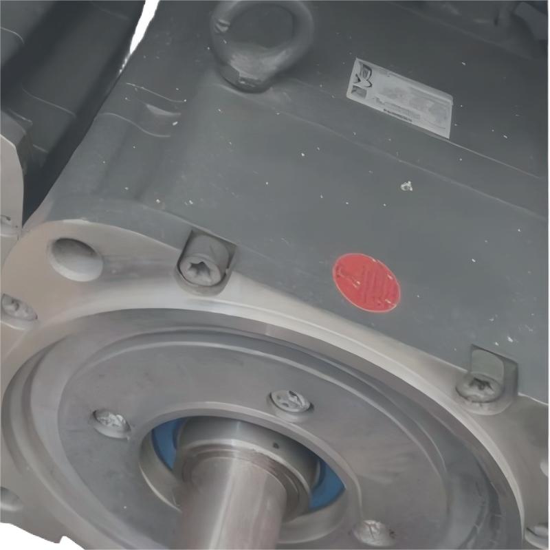
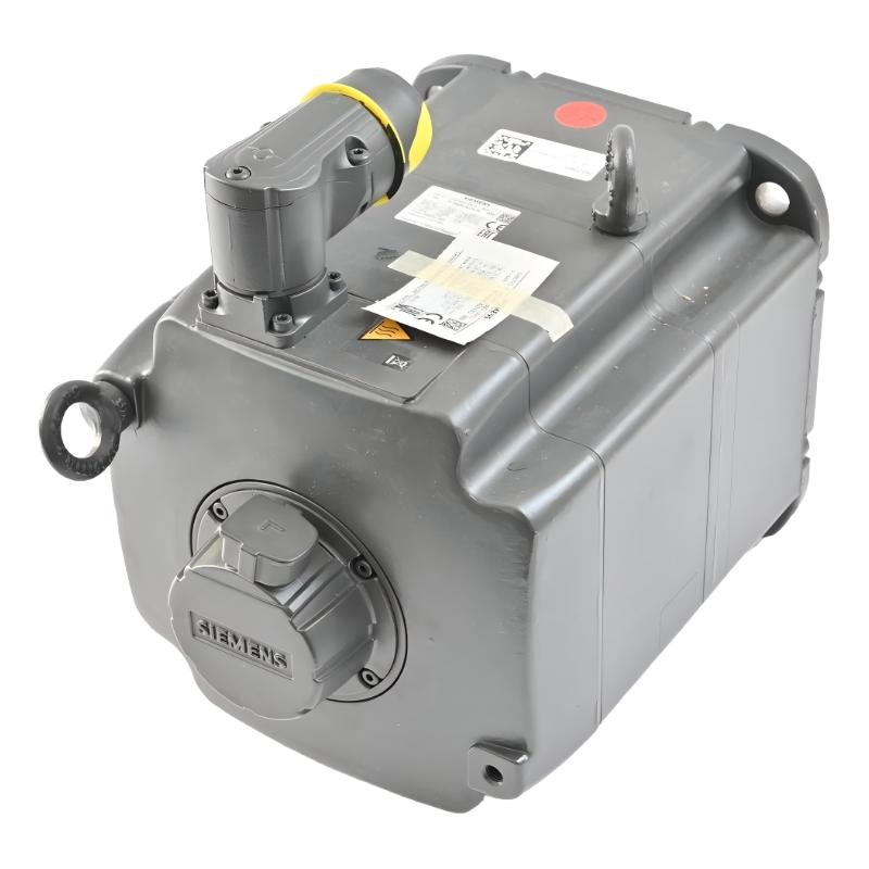
- Siemens
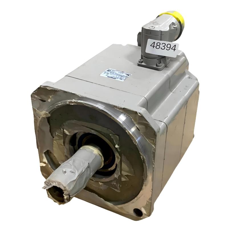
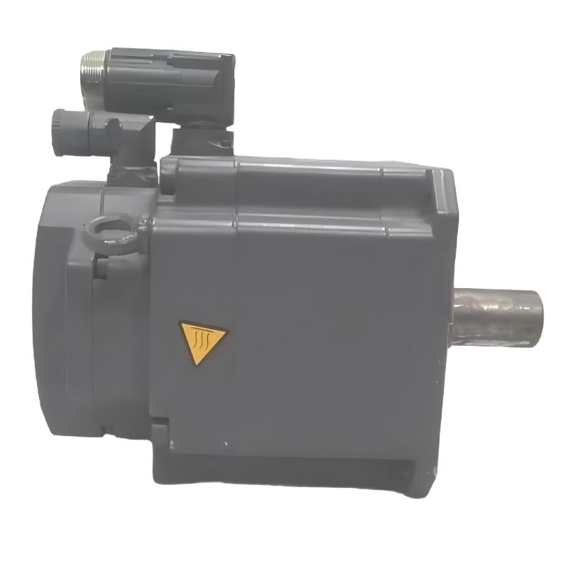
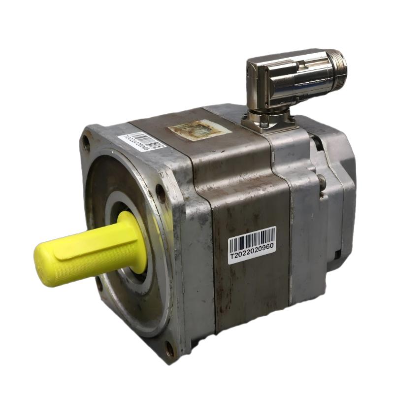
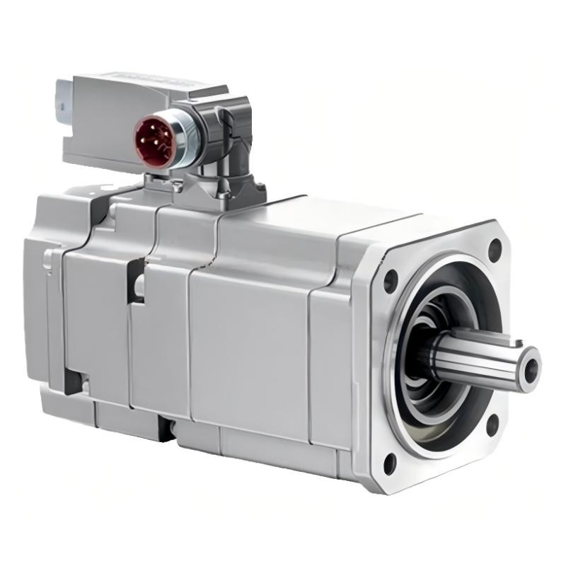
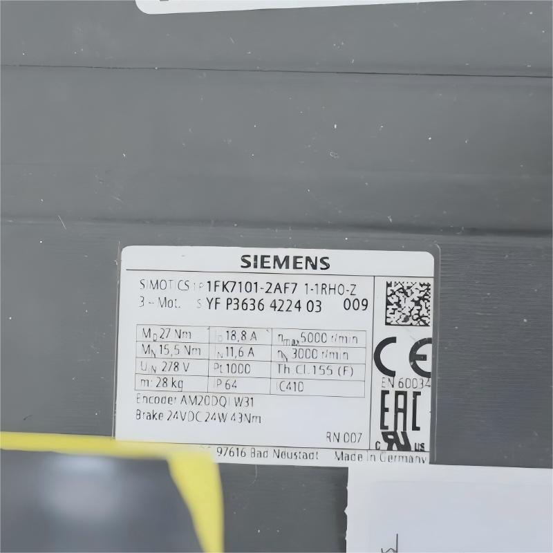
- 1FK7101-2AF71-1RH0
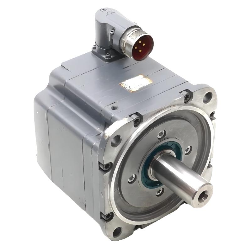
- SIMOTICS S Synchronous Motor
- Germany
- 345 × 195 × 250 mm
- 23.3kg
- Xiamen, China
- New & In Stock
- T/T, PayPal, Western Union
- 1 Year
- 1-3 Working Days
- DHL, UPS, TNT, FedEx and EMS.
- 24-Hour Service
- COO
- 6
Our advantage

Global Logistics
We have a 10-year logistics and express cooperation agreement, so our products can be shipped to any place in the world.

Brand new and original
Our products are imported in bulk from the place of origin. Because of the cooperative relationship, our products are all original and 100% new.

24-hour service
We provide 7*24 hours service to our customers. We will be there whenever you need us.

Price advantage
All our products are priced very favorably because we have our own warehouse and supply.
| Company Information | |||
| [email protected] | |||
| Mobile | +8615980777398 | ||
| +8615980777398 | |||
| 15980777398 |
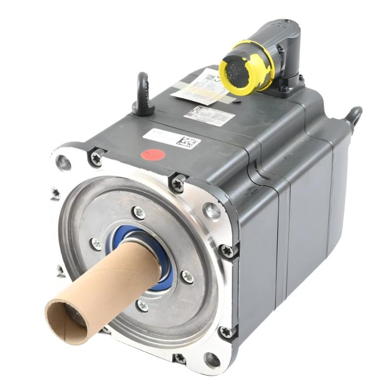
Siemens 1FK7101-2AF71-1RH0 Servo Motor: Product Description, Technical Specifications, Applications and Advantages
1. Product Overview
The Siemens 1FK7101-2AF71-1RH0 is a high-performance synchronous servo motor in the SIMOTICS S 1FK7-CT series. It is designed for industrial motion-control systems that require accurate positioning, dependable torque delivery, smooth rotation and reliable operation under changing loads.
With an optimum operating power of approximately 4.8–4.9 kW and an optimum speed of 3,000 rpm, this motor is suitable for machinery that needs a combination of speed, torque and controlled movement. Its permanent-magnet synchronous design supports precise control when paired with a compatible servo drive and feedback system.
The motor features natural cooling, flange mounting, a rotatable power connector and an absolute encoder with 20-bit single-turn and 12-bit multi-turn feedback. The RH0 configuration includes a holding brake, which can help keep a vertical axis or other gravity-loaded mechanism in position when the drive is not actively producing torque.
This model is best suited to applications where repeatability, controlled acceleration and deceleration, and dependable machine operation are important. Actual performance depends on the selected drive, supply and DC-link conditions, control settings, load inertia, duty cycle and installation environment.
2. Brand and Product Series
| Item | Description |
|---|---|
| Brand | Siemens |
| Product family | SIMOTICS S |
| Product series | 1FK7-CT |
| Product type | Permanent-magnet synchronous servo motor |
| Model | 1FK7101-2AF71-1RH0 |
| Motor design | Naturally cooled |
| Mounting arrangement | Flange-mounted |
| Feedback system | Absolute encoder, 20-bit single-turn + 12-bit multi-turn |
| Brake | Integrated holding brake |
| Typical drive environment | Compatible SINAMICS servo-drive systems; confirm exact drive compatibility |
| Main purpose | Precise speed, torque and position control in industrial machinery |
The 1FK7-CT series is intended for demanding motion-control duties. Its main role is to convert electrical power into accurately controlled mechanical movement. In a correctly configured system, the servo drive uses feedback from the motor encoder to regulate the motor’s position, speed and torque.
The model number is important when ordering replacement equipment. Motors that share the same basic frame or series can differ in rated speed, winding, encoder, brake, shaft configuration, connector arrangement and degree of protection. A close-looking model is not automatically a direct substitute.
3. Detailed Technical Parameters
The following table summarizes the principal technical characteristics of the 1FK7101-2AF71-1RH0. Values such as rated torque and maximum speed describe different operating conditions and should not be treated as continuously available output under every load.
| Parameter | Specification |
|---|---|
| Model number | 1FK7101-2AF71-1RH0 |
| Brand | Siemens |
| Series | SIMOTICS S 1FK7-CT |
| Motor type | Permanent-magnet synchronous servo motor |
| Optimum operating power | Approx. 4.8–4.9 kW |
| DC-link voltage class | 600 V DC |
| Rated speed | 3,000 rpm |
| Optimum operating speed | 3,000 rpm |
| Rated torque at 100 K temperature rise | 15.5 Nm |
| Static torque at 60 K temperature rise | 22.5 Nm |
| Static torque at 100 K temperature rise | 27 Nm |
| Maximum torque | 80 Nm |
| Rated current | 11.6 A |
| Stall current at 60 K temperature rise | 15.2 A |
| Stall current at 100 K temperature rise | 18.8 A |
| Maximum current | 63 A |
| Number of poles | 8 |
| Maximum permissible mechanical speed | 5,000 rpm |
| Maximum permissible inverter speed | 5,000 rpm |
| Torque constant at 100 K | Approx. 1.435 Nm/A |
| Voltage constant at 20°C | Approx. 92.5 V per 1,000 rpm |
| Winding resistance at 20°C | Approx. 0.141 Ω |
| Winding inductance | Approx. 3.5 mH |
| Electrical time constant | Approx. 25 ms |
| Mechanical time constant | Approx. 1.62 ms |
| Thermal time constant | Approx. 60 min |
| Rotor moment of inertia | Approx. 106.6 kg·cm² |
| Efficiency | Approx. 93% |
| Cooling method | Natural cooling |
| Mounting arrangement | IM B5 flange mounting; also suitable for IM V1 and IM V3 arrangements where permitted |
| Encoder | AM20DQI absolute encoder |
| Encoder resolution | 20-bit single-turn + 12-bit multi-turn |
| Encoder interface | DRIVE-CLiQ |
| Shaft type | Smooth shaft, tolerance N |
| Holding brake | Integrated permanent-magnet holding brake |
| Degree of protection | IP64 |
| Approximate dimensions | 345 × 195 × 250 mm; confirm orientation and measurement points against the exact mechanical drawing |
| Net weight | Approx. 23.3 kg |
| Operating environment | Industrial machinery; comply with the specified ambient, installation and cooling conditions |
Understanding the Main Ratings
Rated power and rated torque: The motor’s optimum power is approximately 4.8–4.9 kW at 3,000 rpm. The rated torque of 15.5 Nm is the relevant continuous-duty reference under the specified thermal conditions. The static torque figure of 27 Nm is a different rating and should not be interpreted as the motor’s continuous torque at every speed.
Maximum torque: The listed maximum torque of 80 Nm describes a short-duration operating limit under specified drive and motor conditions. The actual torque available at a given speed depends on the servo drive, current limit, DC-link voltage and operating envelope.
Maximum speed: The maximum permissible speed is not necessarily the speed that should be used continuously. The application must also satisfy load, bearing, lubrication, mechanical safety and drive-control requirements.
Holding brake: The integrated brake is primarily intended to hold a stationary axis. It should not normally be used as a working brake for repeated dynamic stopping unless the application and brake specifications explicitly allow that duty. For vertical axes, the machine design should also consider the consequences of power loss and the need for independent mechanical safety measures.
Dimensions and weight: The approximate overall dimensions are useful for initial layout planning, but the final installation should be based on the exact motor drawing. Connector orientation, shaft extension, flange details and brake configuration can affect clearances and interchangeability.
4. Product Introduction
The 1FK7101-2AF71-1RH0 is designed for machinery that needs more than simple constant-speed rotation. A servo motor must accelerate, decelerate, change direction and reach commanded positions with predictable behavior. This model combines a permanent-magnet synchronous motor design with high-resolution absolute position feedback to support those tasks.
During operation, the servo drive supplies controlled electrical current to the motor windings. The motor’s magnetic field interacts with the permanent magnets in the rotor, producing rotational torque. The drive continuously regulates motor current and uses encoder feedback to track commanded speed or position.
The absolute encoder is particularly useful in applications where the control system needs precise position information. Its multi-turn capability records position across multiple shaft rotations, subject to the encoder’s specified operating and reference conditions. This can simplify certain positioning routines compared with systems that rely solely on incremental feedback and a separate homing procedure.
The motor’s flange-mounted construction supports rigid installation on machine frames, gearboxes or other mechanical assemblies designed for the relevant mounting interface. A properly aligned coupling or transmission helps transfer torque while limiting unwanted radial and axial loads on the motor shaft.
The RH0 configuration also includes an integrated holding brake. This is valuable when an axis must remain stationary while the servo drive is disabled or when a machine sequence requires a defined holding state. The brake must be integrated into the machine’s control and safety logic correctly, rather than treated as a substitute for the servo drive’s normal motion control.
Natural cooling keeps the motor construction relatively straightforward, without requiring a separate liquid-cooling circuit. However, adequate airflow and thermal clearance remain important. Installing the motor in a tightly enclosed space or operating it with frequent high-torque cycles can change its thermal behavior and may require a revised duty-cycle assessment.
5. Product Applications

5.1 CNC Machine Tools
The motor can be used in suitable machine-tool feed axes, indexing mechanisms and auxiliary positioning systems. Its encoder feedback helps the controller manage commanded motion, while its torque capability supports acceleration and controlled movement of mechanical assemblies. Final suitability depends on axis inertia, required accuracy, cutting forces and the drive configuration.

5.2 Packaging and Production Lines
Packaging equipment often requires repeated starts and stops, synchronized movement and accurate positioning of product-handling mechanisms. This motor may be used in feed rollers, cutting mechanisms, indexing tables and other controlled-motion axes when the torque-speed curve matches the duty cycle.

5.3 Material Handling and Automation
Automated handling systems use servo motors to position fixtures, transfer parts and move mechanical slides. The absolute encoder helps the control system monitor movement, while the holding brake can be useful for suitable stationary or gravity-loaded axes when correctly engineered.

5.4 Assembly and Indexing Machines
Assembly equipment frequently relies on repeatable movement between fixed stations. A servo system built around this motor can coordinate positioning, dwell periods and controlled acceleration, helping maintain consistent cycle timing in automated production.

5.5 Printing and Converting Equipment
Web-handling, feeding and converting machines may require coordinated shaft speed and controlled motion. A suitable servo configuration can help maintain repeatable movement and synchronization, provided the required continuous torque, peak torque and operating speed remain within the system’s limits.
Other possible uses include automated test equipment, special-purpose machinery, indexing mechanisms and industrial production systems with frequent position changes. The motor should be selected only after the required torque, speed, inertia, duty cycle and environmental conditions have been checked.
6. Main Product Advantages
6.1 Precise Position Feedback
The 20-bit single-turn and 12-bit multi-turn absolute encoder provides detailed position feedback for compatible control systems. This supports accurate positioning and repeatable motion when the encoder, servo drive and machine controller are configured correctly.
6.2 Strong Torque Capability
The motor provides a rated torque of approximately 15.5 Nm and a specified static torque of 27 Nm at a 100 K temperature rise. Its listed maximum torque of 80 Nm gives the drive system a higher short-duration torque capability within the applicable operating limits.
6.3 Integrated Holding Brake
The holding brake is useful where a stationary axis must remain in position during defined operating states. It can be particularly relevant to vertical mechanisms, although brake sizing, control logic and mechanical safety measures must be evaluated for each application.
6.4 High-Speed Operation
With a rated speed of 3,000 rpm and a specified maximum permissible speed of 5,000 rpm, the motor can support a range of industrial motion profiles. The usable speed depends on load torque, the drive’s current and voltage limits, and the machine’s mechanical constraints.
6.5 Compact Industrial Construction
The flange-mounted design helps integrate the motor into equipment with a compatible mounting interface. Its approximate weight of 23.3 kg should be considered during machine design, support-bracket selection, transport and installation.
6.6 Natural Cooling
Natural cooling avoids the need for a separate liquid-cooling circuit. The machine designer must still provide sufficient heat dissipation and ensure that nearby components, mounting surfaces and enclosure conditions do not compromise cooling.
6.7 Flexible Integration
The encoder’s DRIVE-CLiQ interface supports integration with compatible drive systems. The motor is most effective when used with a properly selected servo drive, suitable power and feedback cables, and a controller configured for the specific motor data.
6.8 Suitable for Demanding Motion Cycles
Servo control allows the system to coordinate acceleration, deceleration, speed changes and positioning commands. The motor can therefore serve applications that need controlled movement rather than simple on/off operation, provided the selected duty cycle stays within the permitted thermal and mechanical limits.
7. Related Models in the Same Series
The models below are closely related to the 1FK7101-2AF71-1RH0. Several share the same basic motor family and performance class but differ in brake, encoder, shaft or protection configuration. The table is intended for comparison and shortlisting, not as confirmation that each model is a drop-in replacement.
| Model number | Main configuration | Power / speed | Torque information | Brake / protection | Dimensions | Weight |
|---|---|---|---|---|---|---|
| 1FK7101-2AF71-1RH0 | Reference model; AM20DQI absolute encoder; smooth shaft | Approx. 4.8–4.9 kW / 3,000 rpm | 15.5 Nm rated; 27 Nm static at 100 K | Brake; IP64 | Approx. 345 × 195 × 250 mm | Approx. 23.3 kg |
| 1FK7101-2AF71-1RH1 | Similar motor with holding brake and IP65 protection | Approx. 4.9 kW / 3,000 rpm | 15.5 Nm rated; 27 Nm static at 100 K | Brake; IP65 | Confirm exact drawing | Approx. 23.3 kg |
| 1FK7101-2AF71-1RG0 | Similar motor with absolute encoder; no holding brake | Approx. 4.9 kW / 3,000 rpm | 15.5 Nm rated; 27 Nm static at 100 K | No brake; IP64 | Confirm exact drawing | Approx. 23.0 kg |
| 1FK7101-2AF71-1RA2 | Absolute encoder; keyed shaft; no holding brake | Approx. 4.9 kW / 3,000 rpm | 15.5 Nm rated; 27 Nm static at 100 K | No brake; IP65 configuration | Confirm exact drawing | Approx. 23.0 kg |
| 1FK7101-2AF71-1UG0 | Resolver feedback; smooth shaft; no holding brake | Approx. 4.9 kW / 3,000 rpm | 15.5 Nm rated; 27 Nm static at 100 K | No brake; IP64 | Confirm exact drawing | Approx. 23.0 kg |
How to Choose Between These Related Models
– Choose 1FK7101-2AF71-1RH0 when the existing installation specifically requires the RH0 brake configuration and IP64 protection.
– Consider 1FK7101-2AF71-1RH1 when IP65 protection is required, but verify the complete mechanical and electrical configuration before substitution.
– Consider 1FK7101-2AF71-1RG0 when the application does not require a holding brake and the existing drive system supports the encoder configuration.
– Consider 1FK7101-2AF71-1RA2 when a keyed shaft is required for the coupling or transmission. Shaft geometry must match the driven equipment.
– Consider 1FK7101-2AF71-1UG0 when resolver feedback is required by the intended control architecture. It is not an automatic substitute for an absolute-encoder motor.
The suffixes matter. Before replacing a motor, compare the full part number, shaft dimensions, flange pattern, brake characteristics, encoder interface, connector orientation, protection rating and compatible drive data.
8. Five Other Siemens Models Worth Considering
The following models provide alternatives across different sizes and configurations. Their output ratings differ, so they should be treated as candidates for different load requirements rather than direct equivalents to the 1FK7101-2AF71-1RH0.
| Model number | Series / type | Representative power | Representative speed | Torque reference | Dimensions | Weight |
|---|---|---|---|---|---|---|
| 1FK7100-2AF71-1RH0 | SIMOTICS S 1FK7-CT servo motor | Approx. 3.8 kW | 3,000 rpm | Approx. 12 Nm rated; 18 Nm static at 100 K for the corresponding motor family | Confirm exact drawing | Confirm exact variant |
| 1FK7083-2AC71-1 | SIMOTICS S 1FK7 servo motor | Approx. 2.6 kW | 2,000 rpm | Approx. 12.5 Nm rated; 16 Nm static at 100 K | Confirm exact drawing | Confirm exact variant |
| 1FK7063-2AF71-1 | SIMOTICS S 1FK7 servo motor | Approx. 1.5 kW | 3,000 rpm | Approx. 4.7 Nm rated; 6 Nm static at 100 K | Confirm exact drawing | Confirm exact variant |
| 1FK7042-2AF71-1 | SIMOTICS S 1FK7 servo motor | Approx. 0.8 kW | 3,000 rpm | Approx. 2.6 Nm rated; 3 Nm static at 100 K | Confirm exact drawing | Confirm exact variant |
| 1FK7060-2AF71-1 | SIMOTICS S 1FK7 servo motor | Approx. 1.5 kW class; confirm exact winding | Confirm exact variant | Confirm exact variant | Confirm exact drawing | Confirm exact variant |
Important: These are family-level comparison references. Some entries use a base model designation rather than a complete order number; the final suffix determines the actual configuration. The stated power and torque values must be checked against the full order number and its technical data before purchasing or using them in a design.
Choosing a Suitable Alternative
If the application currently uses a 1FK7101-2AF71-1RH0, a smaller motor may be suitable only if the load and motion profile require less torque and power. Selecting by kilowatts alone is not sufficient: acceleration torque, reflected inertia, peak load, continuous duty, speed range and braking requirements all affect the decision.
For a replacement project, the closest motor in the same 1FK7-CT family is generally the first place to look. A different motor family or frame size may still be suitable, but it can require changes to mounting, cabling, drive configuration and machine control parameters.
9. Installation and Commissioning Considerations
Correct installation is essential to obtain the expected performance and service life from the motor.
Mechanical mounting: Check that the mounting flange, bolt pattern, shaft dimensions and coupling match the machine. The motor should be aligned with the driven equipment to avoid excessive radial or axial loading.
Electrical connection: Use power and feedback cables compatible with the selected motor and servo drive. Confirm connector pin assignments, cable ratings, shielding and grounding arrangements before energizing the system.
Drive configuration: Enter or select the exact motor data in the compatible drive configuration. The encoder type, motor identification, current limits, speed limits and control parameters should match the actual motor.
Brake control: Verify the brake’s electrical ratings and release sequence. A holding brake must be released and applied in the correct sequence relative to torque generation and drive shutdown. For a vertical axis, assess the risk of movement when the brake is released or when power is lost.
Thermal conditions: Maintain the required clearance around the motor and avoid restricting heat dissipation. Review the duty cycle if the application includes frequent high-torque acceleration, repeated stops or sustained operation at low speed with heavy load.
Protection and environment: IP64 indicates protection against dust ingress at the specified level and splashing water; it does not mean the motor is suitable for high-pressure washing or immersion. The complete assembly must be appropriate for the actual environment.
Commissioning checks: Before full-load operation, verify motor direction, encoder feedback, brake function, current behavior, operating temperature and mechanical vibration. Increase load gradually while monitoring the system against its specified limits.
10. Maintenance and Service Life
A servo motor can provide long service when installed and operated within its limits, but maintenance should be based on the application and the equipment manufacturer’s instructions.
– Inspect connectors, cables and protective grounding for looseness, wear or damage.
– Monitor vibration, abnormal noise and temperature changes that may indicate alignment issues, bearing wear or excessive loading.
– Check the holding brake according to the prescribed inspection procedure, especially where the machine depends on it to hold a load safely.
– Keep the mounting area clean enough to preserve heat dissipation and prevent contamination from affecting connectors or nearby components.
– Investigate recurring drive faults rather than repeatedly resetting them. Faults may be caused by encoder wiring, incorrect parameterization, mechanical binding, overload or an unsuitable acceleration profile.
– When replacing the motor, preserve the original configuration records where available, including motor identification, drive parameters, encoder setup, brake wiring and machine reference positions.
The motor’s rated life cannot be determined from its model number alone. Actual service life depends on load, temperature, installation quality, bearing conditions, vibration, contamination and operating hours.
11. Product Summary
The Siemens 1FK7101-2AF71-1RH0 is a SIMOTICS S 1FK7-CT synchronous servo motor with approximately 4.8–4.9 kW optimum operating power, 3,000 rpm rated speed, 15.5 Nm rated torque, a 27 Nm static torque rating at a 100 K temperature rise, absolute encoder feedback and an integrated holding brake.
Its main strengths are precise motion feedback, strong short-duration torque capability, flange-mounted construction and a configuration suitable for demanding industrial positioning tasks. The brake and encoder configuration make it particularly relevant to machinery that requires controlled movement and a defined holding state.
For an exact replacement, the full model number should be matched against the existing motor. Confirm the brake configuration, encoder interface, shaft and flange dimensions, protection rating, cable arrangement, drive compatibility and weight before ordering. These checks are more reliable than selecting a motor based on series name or rated power alone.