

ProductPRODUCT
Featured products
Contact Us
- Siemens
- 1FK7063-2AF71-1CH1
- Synchronous Motor
- Germany
- 63 mm
- 11.400 kg
- Xiamen, China
- New & In Stock
- T/T, PayPal, Western Union
- 1 Year
- 1-3 Working Days
- DHL, UPS, TNT, FedEx and EMS.
- 24-Hour Service
- COO
- 4
Our advantage

Global Logistics
We have a 10-year logistics and express cooperation agreement, so our products can be shipped to any place in the world.

Brand new and original
Our products are imported in bulk from the place of origin. Because of the cooperative relationship, our products are all original and 100% new.

24-hour service
We provide 7*24 hours service to our customers. We will be there whenever you need us.

Price advantage
All our products are priced very favorably because we have our own warehouse and supply.
| Company Information | |||
| [email protected] | |||
| Mobile | +8615980777398 | ||
| +8615980777398 | |||
| 15980777398 |
Product Overview
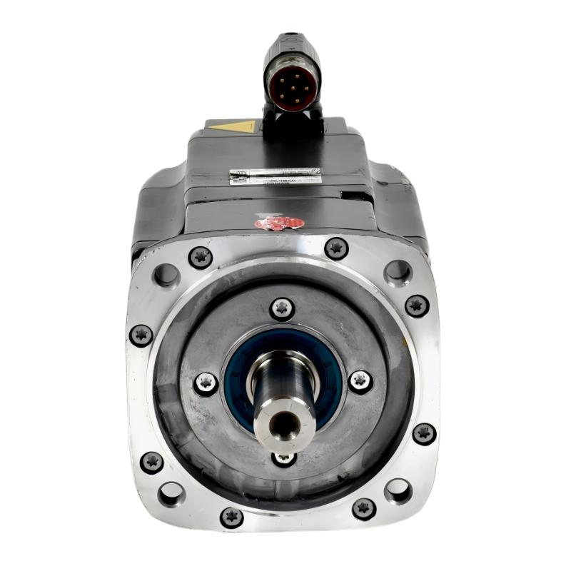
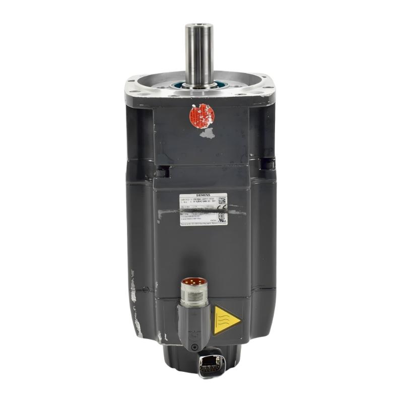
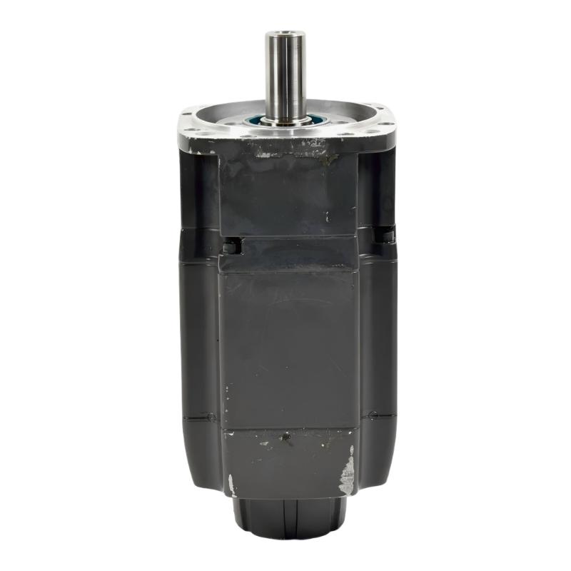
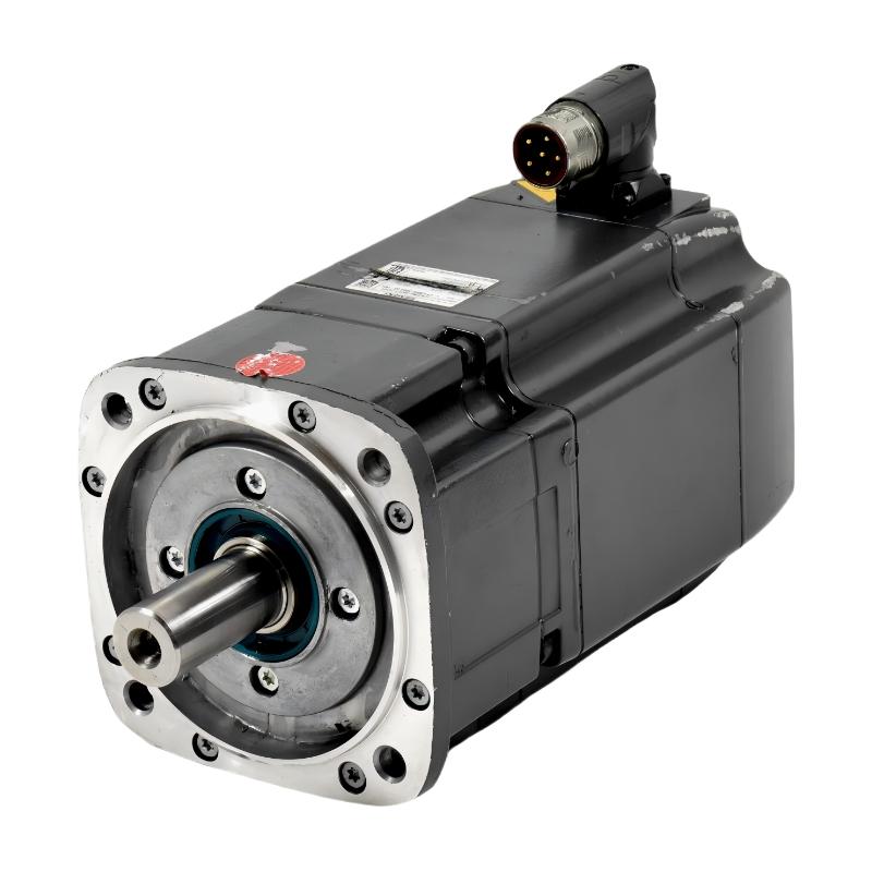
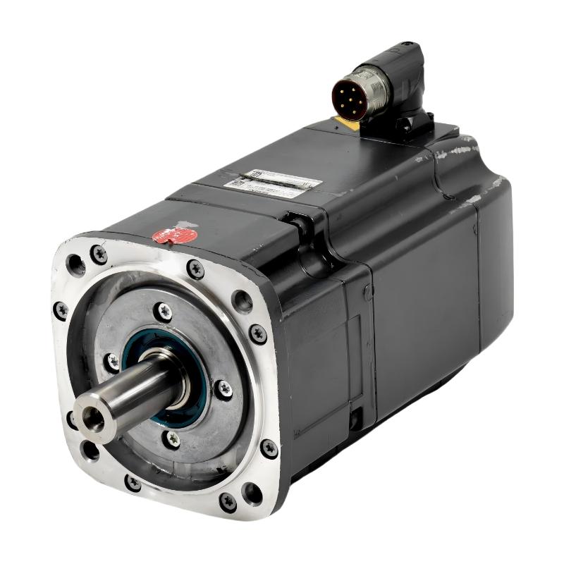
The Siemens 1FK7063-2AF71-1CH1 SIMOTICS S Synchronous Motor is a permanent-magnet synchronous motor from the SIMOTICS S-1FK7 compact motor family. It is intended for industrial servo applications that require controlled rotation, repeatable positioning, and coordinated movement under a compatible drive system. This configuration combines natural cooling, an absolute multiturn encoder with DRIVE-CLiQ communication, a smooth shaft, and an integrated holding brake.
In a servo-motion system, the motor converts electrical energy into mechanical torque while the drive regulates its response to motion commands. Feedback from the encoder allows the drive to monitor rotor position and coordinate speed and torque control. This arrangement supports applications in which machine movements must follow defined operating sequences rather than run continuously at an uncontrolled speed.
The 1FK7063-2AF71-1CH1 has a rated power of 2.3 kW, a rated speed of 3,000 rpm, and a rated torque of 7.3 Nm under the specified 100 K temperature-rise condition. Its static torque rating at the same condition is 11 Nm. These figures help establish whether the motor can meet an application’s basic operating requirements, but final selection also requires evaluation of acceleration, load inertia, peak torque, duty cycle, and the capabilities of the connected drive.
One of the defining features of this model is its AM24DQI absolute encoder. The encoder provides 24-bit single-turn position information and 12-bit multiturn information through the DRIVE-CLiQ interface. This allows a compatible drive system to obtain detailed rotor-position information for motion control and commissioning. The encoder configuration is particularly relevant when selecting a replacement motor because the feedback interface and supported encoder functions must match the drive architecture.
The integrated holding brake supports applications in which the shaft must remain stationary when the motor is not actively producing torque. The brake uses a permanent-magnet design and has a specified holding torque of 13 Nm. Its electrical control, release sequence, and suitability for a particular load must be assessed against the machine’s requirements. A holding brake should not automatically be treated as a dynamic stopping device or as a complete safety function.
The smooth shaft provides a mechanical interface for suitable couplings and transmission components. This arrangement allows the machine designer to select a coupling based on the connected load, alignment requirements, and torque-transfer method. Proper alignment is important because excessive radial or axial forces can affect bearing life and cause vibration or positioning errors.
Natural cooling dissipates motor heat through the housing and surrounding environment. The installation must therefore provide appropriate thermal conditions for the intended operating duty. Ambient temperature, mounting orientation, surrounding airflow, and repeated high-torque movements can all affect the permissible continuous load.
The motor uses an IM B5 flange mounting arrangement, with IM V1 and IM V3 mounting positions supported as specified for this series. Its IP65 protection rating provides protection against dust ingress and water jets under the conditions defined by the rating. Actual suitability depends on the complete installation, including connectors, cable routing, and the environmental requirements of the machine.
The 1FK7063-2AF71-1CH1 is suitable for integration into compatible Siemens SINAMICS servo-drive systems. Drive selection must account for the motor’s electrical ratings, feedback interface, brake control, speed range, and dynamic load requirements. Correct matching helps ensure that the motor and drive operate as a coordinated motion-control unit.
Typical applications include automated assembly equipment, packaging machinery, material-handling systems, and production machinery requiring controlled rotary movement. In each case, the motor must be evaluated against the actual motion profile and mechanical load rather than selected solely by rated power.
The Siemens 1FK7063-2AF71-1CH1 combines permanent-magnet synchronous motor technology, absolute position feedback, and an integrated holding brake for industrial servo applications. Its performance depends on correct drive configuration, feedback integration, mechanical installation, and commissioning.
Technical Specifications
| Parameter | Specification |
|---|---|
| Manufacturer | Siemens |
| Model | 1FK7063-2AF71-1CH1 |
| Product Family | SIMOTICS S-1FK7 |
| Product Type | Permanent-Magnet Synchronous Motor |
| Motor Series | 1FK7-CT Compact Synchronous Motor |
| Rated Power | 2.3 kW |
| DC-Link Voltage | 600 V DC |
| Rated Speed | 3,000 rpm |
| Rated Torque at 100 K | 7.3 Nm |
| Static Torque at 100 K | 11 Nm |
| Rated Current | 5.6 A |
| Maximum Mechanical Speed | 7,200 rpm |
| Maximum Torque | 35 Nm |
| Cooling Method | Natural cooling |
| Mounting Design | IM B5 (IM V1, IM V3) |
| Flange Size | 1 |
| Encoder Type | Absolute encoder, single-turn and multiturn |
| Encoder Model | AM24DQI |
| Single-Turn Resolution | 24-bit |
| Multiturn Resolution | 12-bit |
| Encoder Interface | DRIVE-CLiQ |
| Shaft Type | Smooth shaft, tolerance N |
| Holding Brake | Integrated permanent-magnet brake |
| Holding Torque | 13 Nm |
| Brake Supply Voltage | 24 V DC ±10% |
| Brake Coil Current | 0.8 A |
| Brake Opening Time | 100 ms |
| Brake Closing Time | 50 ms |
| Temperature Monitoring | Pt1000 temperature sensor |
| Degree of Protection | IP65 |
| Electrical Connections | Rotatable power and signal connectors |
| Recommended Drive Family | Compatible Siemens SINAMICS servo drive systems |
| Shaft Height | 63 mm |
| Weight | 11.400 kg |
Product Features
- Permanent-magnet synchronous design: Produces controlled torque for servo applications requiring regulated rotation and coordinated movement.
- 2.3 kW rated power: Supports industrial motion tasks within the specified electrical and thermal operating limits.
- 3,000 rpm rated speed: Suits servo axes that require controlled rotational speed and repeatable movement.
- AM24DQI absolute encoder: Supplies 24-bit single-turn and 12-bit multiturn position information.
- DRIVE-CLiQ communication: Connects the encoder to compatible Siemens drive systems for feedback and commissioning.
- Integrated permanent-magnet holding brake: Provides a specified 13 Nm holding torque for suitable stationary-load applications.
- Smooth shaft configuration: Supports coupling arrangements selected for the machine’s torque-transfer and alignment requirements.
- Natural cooling: Dissipates heat without requiring a separate forced-air cooling unit mounted to the motor.
- Flange mounting: Supports integration into compatible industrial machine structures and servo-axis assemblies.
- IP65 protection: Provides defined protection against dust ingress and water jets under the specified test conditions.
- Pt1000 temperature monitoring: Supplies winding-temperature information for compatible drive monitoring and protection functions.
Working Principle
The Siemens 1FK7063-2AF71-1CH1 operates as the electromechanical actuator in a closed-loop servo system. The compatible drive supplies controlled current to the motor windings, generating a rotating magnetic field that interacts with the rotor’s permanent magnets. This interaction produces torque and drives the shaft.
Motion Command → SINAMICS Servo Drive → Motor Rotation → DRIVE-CLiQ Feedback → Control Correction
The motion controller generates a position, speed, or torque command according to the machine sequence. The servo drive interprets the command and regulates the electrical current supplied to the motor. Adjusting current allows the drive to control torque and influence the motor’s acceleration, deceleration, and operating speed.
As the rotor moves, the AM24DQI encoder provides absolute position information through DRIVE-CLiQ. Its single-turn data identifies the angular position within one revolution, while the multiturn data represents position across multiple revolutions within the encoder’s specified range. The compatible drive uses this information as part of its motion-control process.
Absolute feedback can simplify position management compared with a system that relies solely on incremental signals. However, the actual startup behavior depends on drive configuration, encoder initialization, and machine reference management. The machine designer must verify the required positioning behavior during commissioning rather than assume that every application can resume operation without additional checks.
The integrated holding brake performs a separate function from electromagnetic torque production. During normal movement, the brake must be released according to the specified control sequence. When the shaft needs to remain stationary, the brake can hold the shaft within its rated conditions. The drive and brake-control arrangement must follow the prescribed release and engagement procedure to avoid unnecessary mechanical stress.
The brake’s holding torque must be evaluated against the actual load, transmission ratio, mechanical efficiency, and any external forces acting on the axis. Applications involving suspended loads or safety-related stopping requirements need an appropriately engineered braking and protection arrangement. The integrated brake alone should not be assumed to provide every required safety function.
The motor’s Pt1000 temperature sensor provides winding-temperature information to compatible monitoring electronics. Correct wiring and parameterization allow the drive system to monitor thermal conditions. This is relevant during extended operation, repeated acceleration cycles, and applications where the load changes significantly over time.
Mechanical torque is transferred from the smooth shaft through a compatible coupling or transmission. Coupling alignment, shaft loading, and load inertia influence the motion response. Poor alignment or excessive mechanical loading can cause vibration, additional bearing stress, and reduced positioning accuracy even when the motor and drive are correctly configured electrically.
Natural cooling removes heat through the motor housing and surrounding environment. The available thermal margin depends on the installation conditions and operating duty. If the application requires frequent high-torque movements or sustained loading, the motor’s thermal limits and the drive’s operating envelope must be checked during engineering.
In normal operation, the controller defines the movement, the drive regulates current, the encoder reports rotor position, and the holding brake provides stationary holding when appropriately engaged. The coordinated operation of these elements supports controlled motion in industrial automation systems.
Role in the Industrial Control Architecture
The 1FK7063-2AF71-1CH1 forms the actuator stage of a servo-motion axis. It receives controlled electrical power from a compatible servo drive and returns absolute encoder information through DRIVE-CLiQ. The integrated holding brake is controlled as part of the overall axis design.
Motion Controller → SINAMICS Servo Drive → 1FK7063-2AF71-1CH1 → Mechanical Load
| System Component | Function |
|---|---|
| Siemens 1FK7063-2AF71-1CH1 | Converts electrical power into controlled mechanical rotation |
| SINAMICS Servo Drive | Regulates motor current, torque, speed, and position |
| SIMATIC Motion Controller or PLC | Generates axis commands and coordinates machine sequences |
| AM24DQI Absolute Encoder | Supplies single-turn and multiturn rotor-position information |
| DRIVE-CLiQ Connection | Transfers encoder data to compatible drive electronics |
| Holding-Brake Circuit | Controls release and engagement of the integrated brake |
| Pt1000 Temperature Sensor | Provides motor temperature information for compatible monitoring functions |
| Motor Power Cable | Supplies electrical power from the drive to the motor |
| Mechanical Coupling | Transfers motor torque to the connected mechanism |
| Gearbox or Transmission | Adapts speed and torque to the load where required |
| Engineering Software | Supports motor identification, drive configuration, tuning, and diagnostics |
The controller determines the required movement, while the drive regulates motor operation using the encoder feedback. The mechanical transmission and holding-brake arrangement must be selected according to the actual axis requirements.
Industrial Applications
| Application | Typical Use |
|---|---|
| Automated Assembly Machines | Positioning tooling, fixtures, and rotary mechanisms |
| Packaging Equipment | Driving indexing mechanisms and synchronized feed systems |
| Material-Handling Machinery | Controlling rotary axes in automated handling equipment |
| Production-Line Automation | Executing repeatable movements within coordinated machine sequences |
| Printing Machinery | Driving controlled feed and positioning mechanisms |
| Industrial Converting Equipment | Regulating rollers and other rotary machine elements |
| Automated Inspection Systems | Positioning fixtures and inspection assemblies |
| Manufacturing Equipment | Providing controlled rotation for process mechanisms |
| Precision Positioning Systems | Using absolute encoder feedback for repeatable axis movement |
| Load-Holding Servo Axes | Supporting applications where an appropriately engineered holding-brake function is required |
Installation and Maintenance
- Confirm drive compatibility: Check the motor’s rated power, current, speed, encoder interface, and brake requirements against the selected servo drive.
- Inspect the motor before installation: Check the connectors, shaft, mounting flange, and enclosure for visible damage that could affect operation.
- Prepare the mounting structure: Ensure that the machine flange and supporting structure are suitable for the specified mounting arrangement and expected operating loads.
- Align the mechanical coupling: Select a coupling compatible with the smooth shaft and maintain the alignment tolerances required by the coupling and motor documentation.
- Connect the motor power cable: Use the appropriate power connection and follow the specified grounding, shielding, and electrical installation practices.
- Connect the DRIVE-CLiQ interface: Use compatible signal cabling and confirm that the encoder is recognized by the drive during commissioning.
- Wire the holding brake correctly: Follow the specified 24 V DC brake supply requirements and verify the brake-control sequence before enabling normal motion.
- Configure the drive parameters: Check the motor data, encoder identification, control mode, speed limits, and brake settings in the engineering environment.
- Verify absolute position feedback: Confirm that the reported rotor position is plausible and that the machine’s reference-management procedure behaves as intended.
- Test the brake function: Verify release and engagement under the approved commissioning procedure, taking the actual load and mechanical arrangement into account.
- Monitor temperature and vibration: Investigate abnormal heating, noise, or vibration that may indicate overload, coupling misalignment, bearing problems, or incorrect tuning.
- Maintain configuration records: Retain the motor identification, drive parameters, encoder settings, brake configuration, and maintenance history for future troubleshooting.
If the axis exhibits positioning errors, inspect the DRIVE-CLiQ connection, encoder configuration, mechanical coupling, and drive parameters. If the brake fails to release or hold as expected, check its wiring, control settings, and mechanical loading before returning the machine to service.
Related Components
| Component | Function |
|---|---|
| Siemens 1FK7063-2AF71-1CH1 SIMOTICS S Synchronous Motor | Provides controlled rotary motion with absolute feedback and an integrated holding brake |
| Siemens SINAMICS Servo Drive | Regulates motor current, torque, speed, and position |
| SIMATIC Motion Controller | Coordinates axis movement and machine sequences |
| DRIVE-CLiQ Cable | Transfers encoder information to compatible drive electronics |
| Motor Power Cable | Supplies electrical power to the motor |
| Holding-Brake Connection | Provides the electrical interface required to control the brake |
| Pt1000 Sensor Connection | Transfers winding-temperature information to compatible monitoring electronics |
| Mechanical Coupling | Transfers torque from the smooth shaft to the driven mechanism |
| Gearbox | Adapts motor speed and torque to the application |
| Engineering Software | Supports drive setup, commissioning, tuning, and diagnostics |
| Industrial Control Cabinet | Houses the servo drive, controller, and associated electrical equipment |
Recommended Related Models
| Model | Product Type | Typical Application |
|---|---|---|
| Siemens 1FK7063-2AF71-1CH1 | SIMOTICS S Synchronous Motor | Absolute multiturn encoder, smooth shaft, and integrated holding brake |
| Siemens 1FK7063-2AF71-1RH1 | SIMOTICS S Synchronous Motor | Related configuration with an absolute encoder and holding brake |
| Siemens 1FK7063-2AF71-1RG0 | SIMOTICS S Synchronous Motor | Absolute encoder configuration with a smooth shaft and no holding brake |
| Siemens 1FK7063-2AF71-1CB2 | SIMOTICS S Synchronous Motor | Absolute encoder configuration with a feather-key shaft and holding brake |
Key Advantages
- Provides controlled rotary movement for compatible servo-drive systems.
- Uses absolute single-turn and multiturn feedback through DRIVE-CLiQ.
- Integrates a permanent-magnet holding brake with a specified 13 Nm holding torque.
- Includes Pt1000 winding-temperature monitoring for compatible drive systems.
- Supports flange-mounted installation and smooth-shaft coupling arrangements.
- Combines motion feedback and brake functionality in one servo-motor assembly.
Technical FAQs
What information does the AM24DQI encoder provide to the servo drive?
The AM24DQI encoder supplies 24-bit single-turn and 12-bit multiturn position information through DRIVE-CLiQ. A compatible drive can use this feedback for rotor-position monitoring and motion control, subject to the configured drive and machine-reference requirements.
How should the integrated holding brake be coordinated with motor movement?
The brake must be released and engaged according to the specified electrical and mechanical procedure. The control sequence should prevent the brake from being used as a routine dynamic stopping device unless the documented ratings explicitly permit that operation.
What should be checked when integrating this motor into an existing SINAMICS axis?
Verify the drive’s compatibility with the motor ratings, AM24DQI encoder interface, holding-brake circuit, and temperature-sensor connection. The machine’s mechanical coupling and motion profile must also be checked before the replacement or installation is commissioned.
Why is Pt1000 temperature monitoring useful during continuous production?
The sensor supplies winding-temperature information to compatible monitoring electronics. This helps the drive system assess thermal conditions during extended operation and repeated acceleration cycles, provided that the sensor connection and monitoring parameters are correctly configured.