

ProductPRODUCT
Featured products
Contact Us
- Schneider
- TWDAMO1HT
- Analog Output Module
- France
- 250 x 102 x 76 mm
- 0.085 kg
- Xiamen, China
- New & In Stock
- T/T, PayPal, Western Union
- 1 Year
- 1-3 Working Days
- DHL, UPS, TNT, FedEx and EMS.
- 24-Hour Service
- COO
- 2
Our advantage

Global Logistics
We have a 10-year logistics and express cooperation agreement, so our products can be shipped to any place in the world.

Brand new and original
Our products are imported in bulk from the place of origin. Because of the cooperative relationship, our products are all original and 100% new.

24-hour service
We provide 7*24 hours service to our customers. We will be there whenever you need us.

Price advantage
All our products are priced very favorably because we have our own warehouse and supply.
| Company Information | |||
| [email protected] | |||
| Mobile | +8615980777398 | ||
| +8615980777398 | |||
| 15980777398 |
1. Product Overview
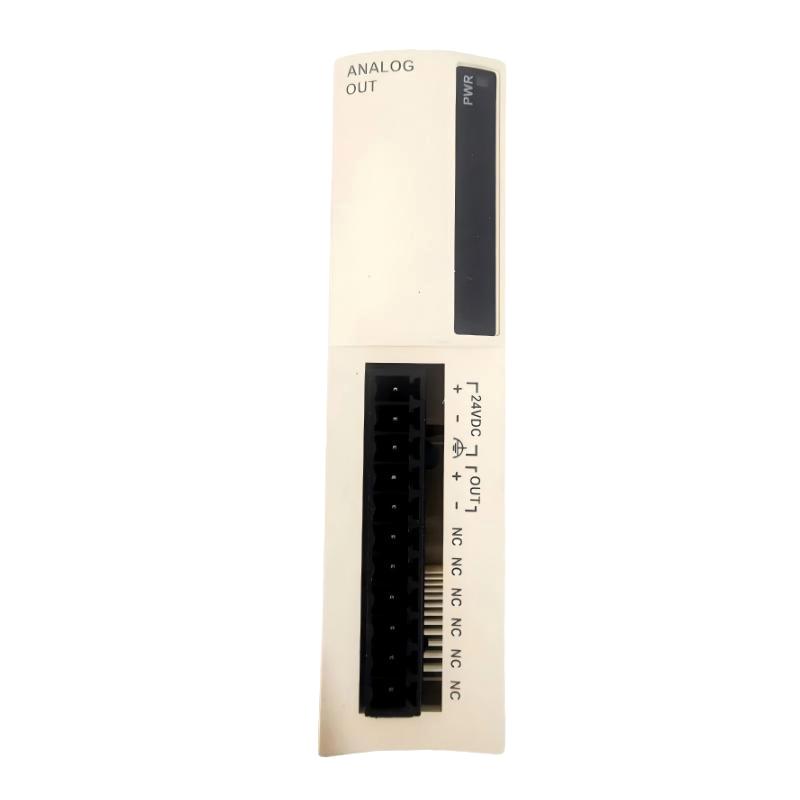
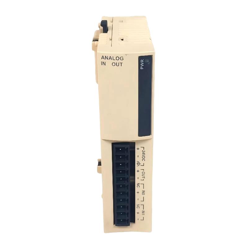
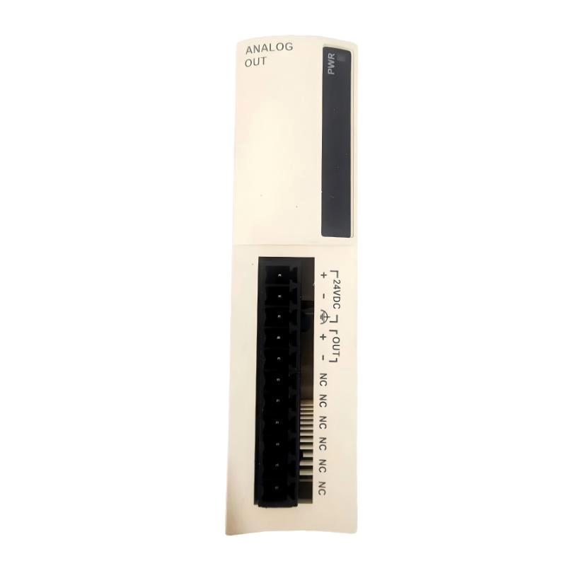
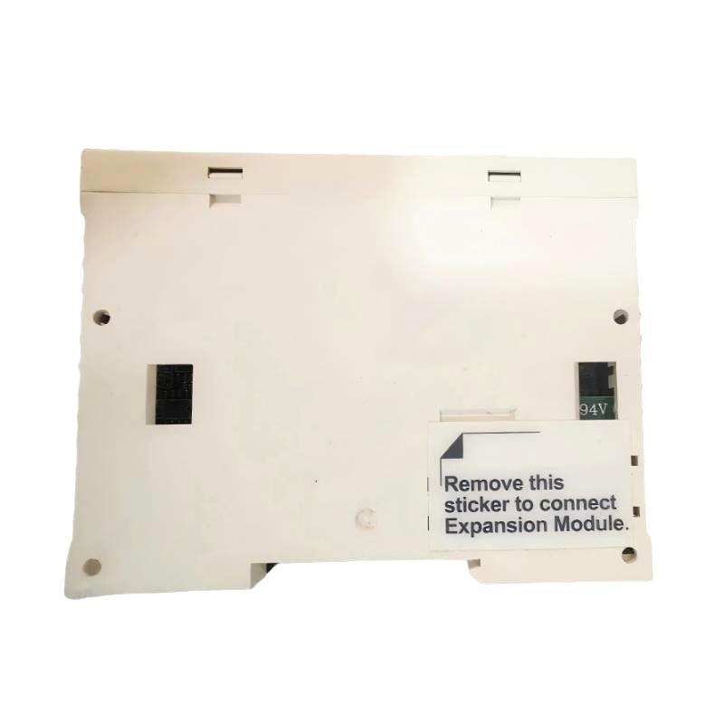
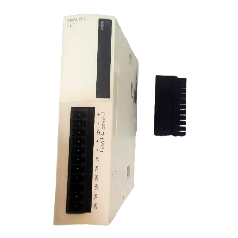
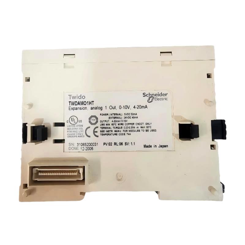
The Schneider Electric TWDAMO1HT Analog Output Module is an analog output expansion module designed for compatible Modicon Twido programmable logic controller (PLC) systems. It provides one configurable analog output channel for transmitting voltage or current reference signals to compatible industrial equipment.
The TWDAMO1HT supports a 0–10 V DC voltage output and a 4–20 mA DC current output. These signal types are widely used in industrial automation for speed references, process setpoints, actuator control interfaces, and communication between controllers and analog-compatible equipment.
With 12-bit output resolution, the module converts digital values from the PLC program into an analog electrical signal. This allows a Twido controller to send a continuously adjustable command to a compatible drive, regulator, or other receiving device. The actual control function depends on the receiving equipment and the application program.
The TWDAMO1HT is particularly relevant to industrial maintenance teams and system integrators responsible for existing Twido-based automation systems. It can help maintain analog command functions in machinery where the original PLC configuration remains in service.
The module uses a removable screw terminal block for field wiring and requires an external 24 V DC supply within its specified voltage range. Proper configuration of the output mode, signal wiring, and receiving-device requirements is essential for reliable operation.
Schneider Electric has discontinued the TWDAMO1HT and does not list a direct replacement for this exact reference. For existing installations, identifying the original model accurately is important when sourcing spare parts or evaluating a modernization project.
Product Highlights
- Manufacturer: Schneider Electric
- Model: TWDAMO1HT
- Product family: Modicon Twido
- Product type: Analog output module
- Number of output channels: 1
- Voltage output: 0–10 V DC
- Current output: 4–20 mA DC
- Output resolution: 12 bit
- Rated supply voltage: 24 V DC
- Allowable supply voltage: 20.4–28.8 V DC
- Connection type: Removable screw terminal block
- Output load: Resistive
- Voltage-mode load impedance: 2 kΩ minimum
- Current-mode load impedance: 300 Ω maximum
- Dimensions supplied: 250 × 102 × 76 mm
- Weight supplied: 0.085 kg
- Lifecycle status: Discontinued
2. Technical Specifications
| Parameter | Specification |
|---|---|
| Manufacturer | Schneider Electric |
| Model number | TWDAMO1HT |
| Product family | Modicon Twido |
| Product category | Analog output expansion module |
| Analog output channels | 1 |
| Voltage output range | 0–10 V DC |
| Current output range | 4–20 mA DC |
| Output resolution | 12 bit |
| Digital output data | 0–4095 in the standard 12-bit range |
| Voltage output LSB | 2.5 mV |
| Current output LSB | 4 µA |
| Output load type | Resistive |
| Minimum voltage-mode load impedance | 2 kΩ |
| Maximum current-mode load impedance | 300 Ω |
| Settling time | Approximately 20 ms |
| Output transfer time | Approximately 20 ms plus one PLC scan cycle |
| Rated supply voltage | 24 V DC |
| Allowable supply voltage | 20.4–28.8 V DC |
| Current consumption at 24 V DC | Approximately 40 mA |
| Internal current consumption at 5 V DC | Approximately 50 mA |
| Output isolation | Photocoupler isolation between output and internal circuit |
| Recommended cable | Shielded twisted-pair cable |
| Output accuracy at 25°C | ±0.2% of full scale, as specified |
| Total output error | ±1% of full scale |
| Output ripple | 1 LSB maximum |
| Operating temperature | 0–55°C |
| Storage temperature | -25–70°C |
| Protection rating | IP20 |
| Connection | Removable screw terminal block |
| Dimensions supplied | 250 × 102 × 76 mm |
| Weight supplied | 0.085 kg |
| Product lifecycle | Discontinued |
Specifications should be checked against the applicable product documentation and system configuration before installation. The dimensions provided above are the supplied listing dimensions and should be confirmed as physical product dimensions rather than packaging dimensions.
3. Function and Working Principle
The TWDAMO1HT converts a digital command generated by a PLC program into a corresponding analog output signal. The receiving device interprets this signal as a reference or setpoint and responds according to its own configuration.
3.1 Digital-to-Analog Conversion
The PLC application calculates an output command and writes the corresponding digital value to the module’s output data area. The module’s digital-to-analog converter converts this value into the selected voltage or current signal.
For example, a PLC may calculate a speed reference for a compatible variable-speed drive. The TWDAMO1HT generates the configured analog signal, and the drive interprets it as a reference according to its own scaling parameters.
The module provides the electrical output interface. It does not independently determine the desired machine speed or execute the drive’s internal control algorithm.
3.2 0–10 V DC Voltage Output
In voltage mode, the module generates an output between 0 and 10 V DC.
With 12-bit resolution, the standard digital range contains 4,096 increments, from 0 to 4095. The nominal voltage step is approximately 2.5 mV per increment.
This output can be used with equipment that accepts a 0–10 V analog reference, provided the receiving input meets the module’s electrical requirements.
Typical examples include:
- Speed-reference inputs on compatible drives.
- Analog setpoint inputs on process controllers.
- Compatible electronic regulators.
- Industrial devices that use voltage-based command signals.
The receiving device must be configured for the same signal range. The voltage output should not be connected to an input intended exclusively for a current loop.
3.3 4–20 mA DC Current Output
In current mode, the module generates a 4–20 mA DC signal. This is a common industrial signal standard because current-loop signals can be useful in electrically noisy environments when properly wired and grounded.
Potential applications include sending a reference to a compatible process controller, regulating device, or industrial drive.
The total current-loop load must remain within the module’s specified maximum load impedance. The designer must account for the receiving input, cable resistance, and other components in the loop.
Correct polarity and compatible input circuitry are essential. The output should not be assumed to supply the power required by arbitrary field equipment.
3.4 Output Scaling
The PLC application maps a digital command to the required engineering range.
For a simple voltage-reference application, the program may map the minimum digital value to 0 V and the maximum digital value to 10 V. A current-reference application may map the configured digital range to 4–20 mA.
The exact scaling must match the receiving device. If the PLC uses custom numerical ranges, the program must account for those ranges when calculating the output value.
Incorrect scaling can cause a drive to run at the wrong speed, a regulator to use an incorrect setpoint, or a process controller to interpret the command incorrectly.
3.5 Output Settling and Response Time
The module’s specified settling time is approximately 20 ms. The total output transfer time is approximately 20 ms plus one PLC scan cycle.
Actual system response depends on the controller scan time, application logic, output loading, cable conditions, and receiving equipment. Engineers should consider these factors when designing control sequences that require predictable response.
For critical applications, validate the complete control loop under realistic operating conditions rather than relying only on the module’s individual response specification.
4. Role in Industrial Automation Systems
4.1 Analog Command Generation
The primary role of the TWDAMO1HT is to provide a programmable analog command to compatible equipment. This allows a Twido PLC to control an external device that accepts a voltage or current reference.
The PLC program determines the requested output value, while the module generates the corresponding electrical signal.
4.2 Variable-Speed Drive Control
Compatible variable-speed drives may accept a 0–10 V DC or 4–20 mA DC reference for speed or another configurable parameter.
When used in this arrangement, the TWDAMO1HT provides the reference signal, while the drive performs motor control. The drive’s analog input settings, scaling, minimum and maximum reference values, and fault behavior must be configured separately.
The module is not a motor drive and cannot directly supply motor power.
4.3 Process Setpoint Adjustment
Some process controllers and regulating devices accept analog setpoints. A Twido PLC can calculate a target value based on operator input, measured conditions, or a programmed sequence, then transmit that value through the TWDAMO1HT.
This arrangement can support process-specific regulation and coordination between different pieces of equipment.
4.4 Machine Automation
In automated machinery, analog outputs can be used to adjust compatible equipment continuously rather than relying only on discrete on/off commands.
The TWDAMO1HT may be suitable for applications requiring a single analog command channel, provided its output range, resolution, accuracy, and response time satisfy the control requirements.
4.5 Maintenance of Legacy PLC Systems
The module is particularly relevant to existing Twido installations where PLC programs, electrical drawings, and connected equipment have been developed around the original hardware.
Using the correct reference for maintenance can help reduce unnecessary wiring and programming changes. If the original module is unavailable, an alternative should be evaluated against the entire control-system configuration.
5. Typical Industrial Applications
Manufacturing and Assembly Equipment
Manufacturing machinery may require a variable command signal for a compatible drive, regulator, or positioning-related device. The module can provide the analog reference where the receiving equipment supports the selected signal type.
Pump and Fan Control
A compatible drive may accept an analog reference for speed adjustment. The PLC can calculate the command based on the machine’s operating sequence, process demand, or other control logic.
The drive must provide the required motor protection and control functions independently.
HVAC and Utility Systems
Certain HVAC and utility devices use 0–10 V or 4–20 mA signals for setpoint adjustment. The TWDAMO1HT can serve as a command output in a compatible Twido-based system.
Process Equipment
Industrial process skids may use an analog command to adjust a compatible regulator or controller. The module can transmit the command generated by the PLC program, provided the signal and load requirements are satisfied.
Packaging Machinery
Packaging equipment may include auxiliary devices that accept an analog reference for speed or process adjustment. The module can provide a single output channel for such functions in a suitable control configuration.
Legacy Equipment Repair
Where the TWDAMO1HT is installed in existing machinery, a replacement module may be needed to restore analog command functionality after a hardware fault. Correct model identification and functional testing are especially important because the original product is discontinued.
6. Installation and System Integration
6.1 Verify PLC Compatibility
Before installing the TWDAMO1HT, confirm that the exact Modicon Twido controller supports the module and the proposed expansion arrangement.
Check the controller reference, available expansion positions, system power requirements, programming software, and module configuration. Do not assume that this module is compatible with other Schneider Electric PLC families simply because they also support analog outputs.
6.2 Confirm the Output Mode
Determine whether the receiving equipment requires 0–10 V DC or 4–20 mA DC.
The PLC configuration and physical wiring must match the selected output mode. A mismatch can result in incorrect signals or equipment malfunction.
6.3 Connect the External Supply
The module uses a rated 24 V DC supply, with an allowable range of 20.4–28.8 V DC.
Verify supply polarity, voltage stability, wiring, and available current capacity. The supply arrangement should follow the product documentation and the electrical design of the complete Twido installation.
6.4 Wire the Analog Output
Use the removable screw terminal block and follow the applicable wiring diagram.
For voltage output, ensure that the receiving input has a minimum impedance of 2 kΩ. For current output, ensure that the total loop impedance does not exceed 300 Ω.
Use shielded twisted-pair cable for analog wiring. Route analog signal cables away from high-current conductors, motor cables, contactors, and other sources of electrical interference whenever practical.
Follow the installation design for cable shielding and grounding. Avoid creating unintended ground loops.
6.5 Configure the PLC Program
Configure the analog output in the Twido application and confirm the output data mapping.
The application should define:
- The intended output signal type.
- The digital-to-engineering-unit scaling.
- The permitted operating range.
- Output limits and interlocks.
- Startup and shutdown behavior.
- The response to PLC or communication faults.
- The conditions under which the output may be enabled.
The safe output state depends on the application and the receiving equipment. Do not assume that the analog output will automatically move to a safe value during every fault condition.
6.6 Test the Output
Before connecting the module to operating equipment, test the output with suitable measuring equipment or an appropriate test load.
Verify that the output corresponds to the programmed command across the intended range. Check the zero or minimum reference, intermediate values, maximum reference, and the expected behavior during startup and shutdown.
For a current output, confirm that the load is within the permitted impedance. For a voltage output, confirm that the receiving device accepts the specified voltage range.
6.7 Commission the Complete System
After verifying the module output, connect the receiving equipment and conduct a controlled functional test.
Check the relationship between the PLC command, the measured analog signal, and the receiving device’s response. Confirm that the equipment does not move or operate unexpectedly when the PLC starts, stops, or enters a fault state.
Document the final wiring, configuration, scaling, and test results for future maintenance.
7. Compatible System Components
The following table identifies common component categories that may be used in a Twido analog-output application.
| Component | Function | Integration Considerations |
|---|---|---|
| Compatible Modicon Twido PLC | Executes control logic | Confirm support for the TWDAMO1HT |
| Compatible Twido expansion arrangement | Connects the analog module to the PLC system | Check module limits and physical configuration |
| 24 V DC power supply | Supplies the module’s required external power | Confirm voltage and current capacity |
| Variable-speed drive | Receives a speed or other analog reference | Verify analog input type, scaling, and parameter settings |
| Process controller | Receives a configurable analog setpoint | Check supported input ranges |
| Compatible regulating device | Uses the analog command to adjust operation | Verify electrical and application requirements |
| Shielded twisted-pair cable | Carries the analog output signal | Follow cable routing and grounding recommendations |
| PLC programming software | Configures the controller and output data | Confirm compatibility with the installed Twido platform |
| HMI or operator panel | Provides operator commands and status display | Confirm communication and program integration |
These are general system component categories. Specific models must be checked for electrical compatibility, controller support, and application suitability before use.
8. Alternative Models and Replacement Considerations
The TWDAMO1HT is discontinued, and Schneider Electric lists no direct replacement for this exact reference. A similar output module may be suitable for a repair or upgrade, but matching the signal type alone does not establish full compatibility.
| Candidate | Product Family | Potential Use | Important Considerations |
|---|---|---|---|
| TWDAMO1HT | Modicon Twido | Original single-channel analog output | Original reference for compatible legacy systems |
| TM2AMO1HT | Schneider Electric TM2 | Similar single-channel analog output functionality | Confirm controller compatibility, wiring, software, and electrical specifications |
| Suitable Modicon TM3 analog output module | Modicon TM3 | Potential option for a compatible newer platform | Select the exact output type and channel count; may require a controller migration |
TM2AMO1HT
The TM2AMO1HT is a candidate for evaluation because it provides a single analog output channel with configurable voltage or current output. However, it must not be treated as an automatic drop-in replacement for the TWDAMO1HT.
Verify the supported PLC family, hardware configuration, terminal wiring, software settings, and output behavior before substituting the module.
Modicon TM3 Analog Output Modules
A suitable TM3 analog output module may be considered when modernizing an automation system. The exact model should be selected according to the required output ranges, resolution, accuracy, number of channels, and supported controller platform.
A TM3 module should not be assumed to operate in the original Twido system. A migration may require a new PLC, software changes, wiring modifications, and full commissioning.
Replacement Selection Checklist
Before ordering an alternative, verify the following:
- Output channel count: Confirm that at least one analog output is available.
- Signal range: Check support for 0–10 V DC or 4–20 mA DC as required.
- Load impedance: Verify that the receiving device and wiring meet the output limits.
- Resolution and accuracy: Confirm that the replacement meets process requirements.
- Controller compatibility: Check the exact PLC and expansion architecture.
- Wiring: Review terminal assignments and signal polarity.
- Software: Check I/O mapping, scaling, and configuration requirements.
- Fault behavior: Confirm output behavior during startup, shutdown, and controller faults.
- Commissioning: Test the output across its operating range before returning the machine to service.
For a legacy repair, a verified original module may minimize engineering changes. For a system upgrade, select an alternative as part of a complete control-system evaluation rather than relying on model similarity alone.
9. Key Advantages
Flexible Analog Output
The module supports both 0–10 V DC and 4–20 mA DC output modes, allowing it to interface with compatible industrial devices using either signal type.
12-Bit Resolution
Its 12-bit digital-to-analog conversion provides 4,096 increments for generating adjustable output commands.
Compact Single-Channel Design
One analog output channel can meet the needs of small applications that do not require a multi-channel analog output module.
Integration with Twido PLC Systems
In compatible configurations, the TWDAMO1HT provides an established interface between a Twido PLC program and external analog-controlled equipment.
Removable Screw Terminal Block
The terminal arrangement supports practical field wiring and maintenance when installed and serviced according to the product documentation.
Useful for Legacy Equipment Support
Correct identification of the original model can help maintenance teams restore analog command functions without immediately redesigning the entire control system.
10. Technical FAQs
What is the Schneider TWDAMO1HT?
It is a single-channel analog output module designed for compatible Schneider Electric Modicon Twido PLC systems.
How many analog outputs does it provide?
It provides one analog output channel.
Which output signals does it support?
It supports 0–10 V DC voltage output and 4–20 mA DC current output.
What is the output resolution?
The module uses 12-bit resolution, providing 4,096 digital increments.
What is the required power supply?
The rated external supply is 24 V DC, with an allowable range of 20.4–28.8 V DC.
What is the maximum current-output load impedance?
The maximum specified load impedance for current output is 300 Ω. The complete loop resistance must remain within the permitted limit.
What is the minimum voltage-output load impedance?
The voltage output requires a load impedance of at least 2 kΩ.
Is the TWDAMO1HT discontinued?
Yes. Schneider Electric lists the model as discontinued, with commercialization ending on December 31, 2016 and standard service ending on December 31, 2021 in the referenced product information.
Does Schneider Electric provide a direct replacement?
No direct replacement is listed for the exact TWDAMO1HT reference. TM2AMO1HT or a suitable newer-platform analog output module may be evaluated, but compatibility must be confirmed.
What are the dimensions and weight?
The supplied listing specifies 250 × 102 × 76 mm and 0.085 kg. Confirm the physical dimensions and net weight before using them for mechanical design or shipping calculations.
11. Procurement and Maintenance Considerations
Because the TWDAMO1HT is discontinued, purchasers should verify the full model reference and the condition of any available stock.
When sourcing this module, consider:
- Confirming the complete part number on the product label.
- Requesting clear photographs of the module and its terminals.
- Checking whether the unit is unused surplus, used, or refurbished.
- Confirming functional testing and warranty terms.
- Verifying that the output mode matches the existing application.
- Reviewing the installed PLC model and expansion configuration.
- Backing up the PLC program before replacement work.
- Confirming dimensions and net weight for logistics planning.
- Testing the replacement output before reconnecting live equipment.
For critical machinery, it is advisable to retain the existing wiring documentation and output scaling values. A replacement should be tested with a suitable load and verified against the receiving equipment’s requirements before the system resumes normal operation.
12. Conclusion
The Schneider Electric TWDAMO1HT Analog Output Module is a single-channel analog output expansion module for compatible Modicon Twido PLC systems. It supports 0–10 V DC voltage output and 4–20 mA DC current output, with 12-bit resolution and a rated 24 V DC supply.
The module can provide analog references for compatible drives, process controllers, and other industrial devices. Its suitability depends on the receiving equipment’s signal requirements, output load, PLC compatibility, and application configuration.
Since the TWDAMO1HT is discontinued and has no direct replacement listed, careful model verification is essential when sourcing spare parts. Alternative modules should be evaluated for hardware compatibility, wiring, software configuration, and fault behavior before installation.
For industrial maintenance and automation procurement teams, accurate identification and proper functional testing can help reduce downtime and support the reliable operation of existing Twido-based control systems.