

ProductPRODUCT
Featured products
Contact Us
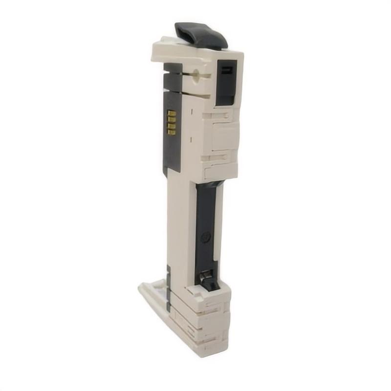
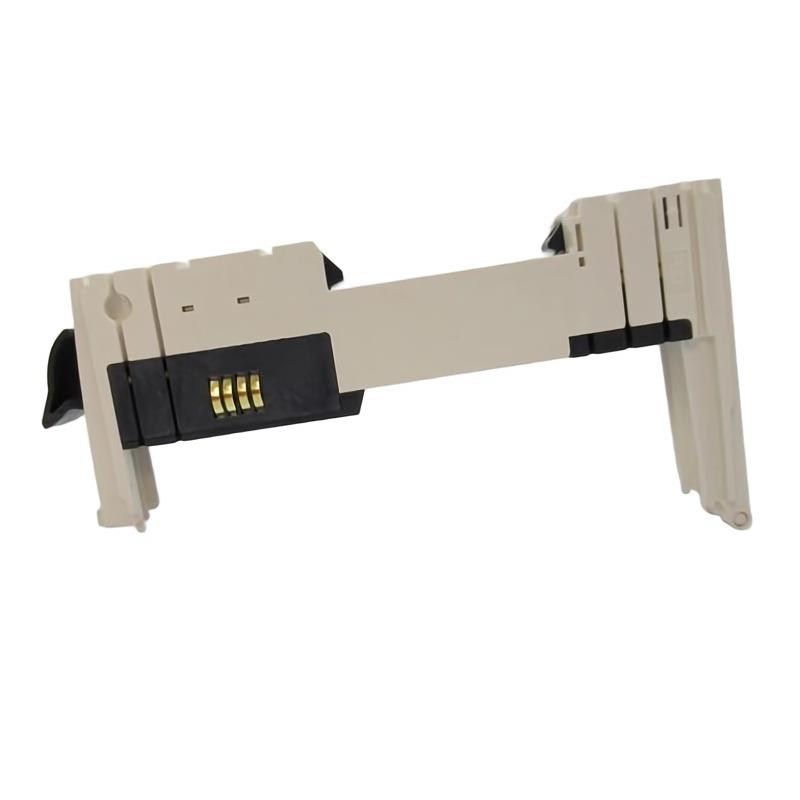
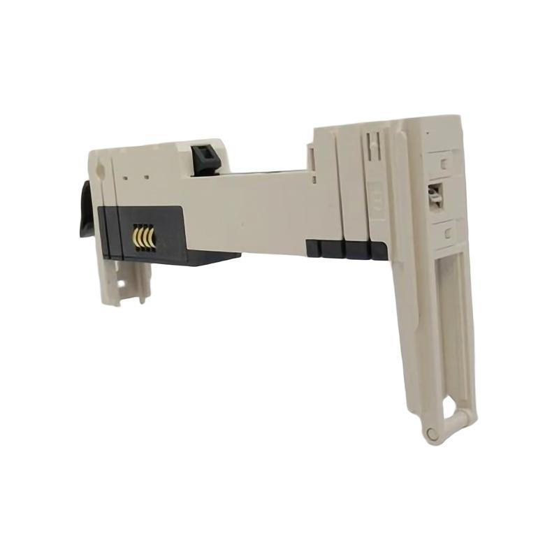
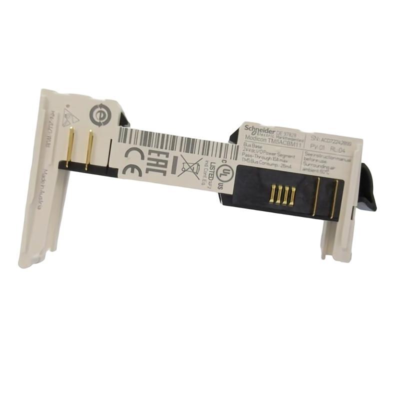
- Schneider
- TM5ACBM11
- Bus Base
- France
- 25 × 73.5 × 90 mm
- 0.02 kg
- Xiamen, China
- New & In Stock
- T/T, PayPal, Western Union
- 1 Year
- 1-3 Working Days
- DHL, UPS, TNT, FedEx and EMS.
- 24-Hour Service
- COO
- 13
Our advantage

Global Logistics
We have a 10-year logistics and express cooperation agreement, so our products can be shipped to any place in the world.

Brand new and original
Our products are imported in bulk from the place of origin. Because of the cooperative relationship, our products are all original and 100% new.

24-hour service
We provide 7*24 hours service to our customers. We will be there whenever you need us.

Price advantage
All our products are priced very favorably because we have our own warehouse and supply.
| Company Information | |||
| [email protected] | |||
| Mobile | +8615980777398 | ||
| +8615980777398 | |||
| 15980777398 |
Product Overview
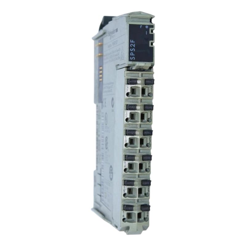
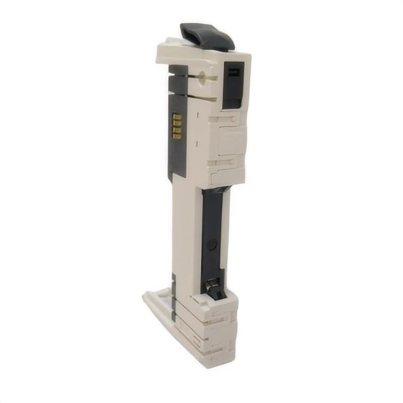
The Schneider Electric TM5ACBM11 Bus Base is an industrial automation hardware component designed to support module mounting and electrical interconnection within a compatible control system. Bus bases provide the physical and electrical interface required to organize modular automation hardware, helping establish reliable connections between installed modules and the associated system architecture.
In modular control applications, individual components must be installed in the correct positions and connected through compatible backplane, bus, or base interfaces. These interfaces help establish the electrical connections required for communication, power distribution, or signal exchange, depending on the design of the specific product family. Correct component selection is therefore important for maintaining a properly configured automation system.
The TM5ACBM11 is identified by the supplied product description as a Schneider Electric bus base. Its compact dimensions of 25 × 73.5 × 90 mm and listed weight of 0.02 kg make it suitable for applications where small-format modular hardware is required. Its precise electrical role, supported module combinations, and mounting requirements should be confirmed against the complete product designation and the applicable system documentation before installation.
For maintenance engineers and industrial procurement teams, verifying the exact part number is essential. Bus bases can have similar physical appearances while differing in their electrical connections, supported modules, or installation arrangements.
Technical Specifications
| Parameter | Specification |
|---|---|
| Manufacturer | Schneider Electric |
| Model Number | TM5ACBM11 |
| Product Type | Bus Base |
| Product Category | Industrial Automation Hardware |
| Primary Function | Modular mounting and interconnection interface |
| Product Family | Confirm against the applicable Schneider Electric documentation |
| Electrical Interface | Verify according to the exact product specification |
| Supported Modules | Confirm before installation |
| Dimensions | 25 × 73.5 × 90 mm |
| Weight | 0.02 kg |
| Installation | Compatible modular automation system; verify mounting requirements |
| Typical Application | Modular control-system integration |
| Replacement Requirement | Match the complete part number and system configuration |
The specifications above retain the supplied model number, product description, dimensions, and weight. Details such as connector assignments, supported module types, bus architecture, electrical ratings, and compatibility should not be assumed without checking the exact hardware documentation.
What Is the Schneider Electric TM5ACBM11 Bus Base?
A bus base is a hardware interface used within certain modular automation systems to provide a mounting location and the necessary electrical connections for compatible components. Rather than wiring every connection independently, a modular architecture uses standardized interfaces to simplify hardware organization and system assembly.
Depending on the product family, a bus base may participate in the mechanical positioning of modules and provide electrical paths for power, communication, or signal interconnection. The specific functions depend on the design of the bus base and the system in which it is installed.
The TM5ACBM11 should therefore be treated as a dedicated hardware component whose compatibility must be established using its complete product identification. It should not be considered interchangeable with another bus base simply because the alternative has similar dimensions or comes from the same manufacturer.
A general modular control arrangement can be represented as:
Control-System Assembly → Compatible Bus Base → Installed Module → System Interconnection
The actual arrangement, module order, and connection method depend on the host automation platform.
Function and Working Principle
1. Mechanical Support
A bus base provides a defined mounting or positioning interface for compatible automation hardware. Correct mechanical installation helps keep modules aligned and ensures that the intended connectors engage properly.
The installation method and required clearances must follow the applicable product instructions.
2. Electrical Interconnection
Depending on its design, a bus base can provide electrical connections between a supported module and the wider automation system. These connections may be associated with power distribution, data exchange, or other system functions.
The exact role of the TM5ACBM11 must be verified from its product documentation rather than inferred from the generic term “bus base.”
3. Modular System Organization
Modular automation equipment is designed around defined component interfaces. Using the correct base helps maintain the intended physical arrangement and electrical connection between supported devices.
An incorrect base may prevent proper installation, create an incomplete connection, or make the assembly incompatible with the host system.
4. Support for Maintenance and Replacement
In a modular control installation, a replaceable base can be an important part of the hardware maintenance process. Correct identification allows technicians to source a component with the required mechanical and electrical characteristics.
Before replacement, the original part number, mounting arrangement, connected module, and relevant system documentation should be checked.
Role in Industrial Automation Systems
Industrial automation systems often combine controllers, interface modules, power components, communication hardware, and field devices. Each component must occupy the correct position and connect through an appropriate interface.
A bus base contributes to this architecture by providing the designated mounting and interconnection point for supported hardware. It is not necessarily a controller or an independent signal-processing device; its role is defined by the product design and the system in which it operates.
Typical system functions associated with modular hardware integration include:
- Establishing the correct physical arrangement of control modules
- Supporting electrical interconnection between compatible components
- Maintaining an organized modular assembly
- Simplifying component identification during maintenance
- Helping technicians replace hardware with the correct part
- Supporting consistent installation practices across control panels
The precise contribution of the TM5ACBM11 to these functions should be established from the applicable Schneider Electric product documentation.
Industrial Applications
Modular Machine Control
Industrial machines often use modular control hardware to organize control and interface components within a compact installation. A compatible bus base can form part of the mounting and interconnection arrangement for such hardware.
Packaging and Assembly Equipment
Packaging lines and assembly machines frequently use modular automation components to support machine sequencing, operator interfaces, and equipment monitoring. Correct base selection helps maintain the intended hardware configuration.
Production-Line Control Cabinets
Control cabinets require components to be mounted securely and connected according to the designed electrical architecture. Compact hardware interfaces can contribute to efficient cabinet organization when they are correctly matched to the installed system.
Material Handling Systems
Conveyor systems and automated material handling equipment may use modular control assemblies to coordinate motors, sensors, actuators, and machine sequences. The bus base’s applicability depends on whether the host system supports the specific component.
Industrial Equipment Maintenance
During maintenance or refurbishment, a bus base may need to be inspected or replaced because of physical damage, connector problems, or an incorrect previous installation. Correct part identification helps reduce the risk of introducing an incompatible component.
These are general examples of modular automation applications, not confirmation that the TM5ACBM11 is approved for every listed system.
Installation and System Integration
Correct installation begins with verifying the product identity and confirming that the bus base matches the intended automation system.
Verify the Part Number
Check the product label and confirm the complete designation TM5ACBM11. Compare it with the original component, equipment bill of materials, and system documentation.
If the part number on the installed component differs from the replacement, do not assume that the parts are interchangeable. Confirm the required revision or alternative designation before proceeding.
Confirm Module Compatibility
Identify the module that will be mounted or connected to the bus base. Verify that the base supports the intended module and that the complete assembly is approved for the host control system.
Connector appearance alone is not sufficient to establish compatibility.
Inspect the Mounting Arrangement
Check the installation position, orientation, mechanical alignment, and available clearance. The bus base should be installed using the mounting method specified for the relevant product family.
Avoid forcing the component into position. Resistance during assembly may indicate misalignment, an incompatible part, or damage to a connector.
Inspect Electrical Connections
Before installation, inspect the relevant connection surfaces and connectors for contamination, deformation, corrosion, or other visible damage.
Follow the prescribed electrical isolation procedure before working on the control system. If the component participates in an energized assembly, do not remove or install it unless the system documentation explicitly permits that procedure.
Verify the Completed Assembly
After installation, confirm that the base and associated module are correctly seated and mechanically secured. Inspect the surrounding wiring and adjacent components for interference or accidental displacement.
Where applicable, perform the system’s prescribed startup checks and review any available controller or module diagnostics before returning the equipment to normal operation.
Troubleshooting the TM5ACBM11 Bus Base
A problem involving a bus base should be investigated together with the connected module, connectors, power arrangements, and host system.
Module Cannot Be Installed Correctly
Possible causes include:
- Incorrect bus-base part number
- Incompatible module type
- Misalignment during installation
- Damaged mounting features
- Deformed connectors
- Incorrect installation orientation
Compare the part number with the equipment documentation and inspect the mechanical interface. Do not force the components together.
Intermittent System Connection
An intermittent connection may be associated with loose seating, damaged contacts, vibration, contamination, or a problem in the connected module.
Inspect the assembly under the applicable safety procedure. Check that all components are properly installed and that connectors show no visible damage.
Module Is Not Recognized
If the host system does not recognize an installed module, the cause may lie in the module itself, the bus interface, the hardware configuration, or another part of the system.
Confirm that the installed module is supported and that the hardware configuration matches the actual assembly. Review available diagnostic messages and follow the manufacturer’s troubleshooting procedure.
Visible Connector Damage
Damaged contacts, broken retention features, discoloration, or deformation can affect mechanical installation and electrical continuity.
A visibly damaged base should be evaluated according to the manufacturer’s maintenance requirements. Avoid attempting improvised repairs to precision connectors or insulating structures.
Fault Persists After Replacement
If replacing the bus base does not resolve the problem, inspect the connected module, adjacent components, system configuration, and associated power or communication connections as applicable.
Replacing one component does not establish that it was the original fault source. A systematic inspection helps avoid unnecessary replacement of otherwise serviceable hardware.
Maintenance Recommendations
Routine inspection can help maintain the integrity of modular automation hardware.
Inspect the physical condition: Check the base for cracks, deformation, damaged mounting features, or other signs of mechanical stress.
Keep connectors clean: Prevent dust, debris, and foreign materials from entering connection areas. Use only approved cleaning methods.
Check mechanical seating: Verify that the base and connected components are correctly positioned and secured.
Review system diagnostics: When a connection-related fault occurs, record the available diagnostic information before replacing hardware.
Maintain accurate inventory records: Record the complete part number and relevant revision information to help ensure correct future procurement.
Follow safe handling procedures: Observe electrical isolation and electrostatic-discharge precautions where required by the equipment design.
Maintenance frequency should be based on the operating environment, system criticality, and applicable manufacturer guidance.
Compatible System Components
A bus base is normally used as part of a larger modular automation assembly. The following table identifies general component categories that may be relevant when planning an installation. It does not establish direct compatibility with the TM5ACBM11.
| Component Category | Typical Function |
|---|---|
| Compatible Control Module | Executes control or interface functions |
| Modular I/O Hardware | Connects field signals to the automation system |
| Power Components | Supply the required electrical power |
| Communication Hardware | Supports data exchange where required |
| Mounting Accessories | Secure the hardware in the designated installation |
| Terminal Blocks | Organize field wiring |
| Industrial Control Cabinet | Provides mechanical and environmental protection |
| Engineering and Diagnostic Tools | Support configuration and maintenance |
Before selecting any related component, confirm the exact product family, electrical interface, mounting arrangement, and supported system configuration.
Replacement and Procurement Considerations
When purchasing a replacement for the Schneider Electric TM5ACBM11 Bus Base, use the complete product designation rather than relying only on the description “bus base.”
Important checks include:
- Complete part number: TM5ACBM11
- Product label and revision information
- Intended host system
- Supported module type
- Connector arrangement
- Mounting dimensions and orientation
- Condition of the replacement component
- Required accessories and installation instructions
The listed physical dimensions are 25 × 73.5 × 90 mm, and the listed weight is 0.02 kg. These values can assist with inventory planning, shipping calculations, and preliminary cabinet-layout preparation.
Physical dimensions and weight alone do not establish electrical or mechanical interchangeability. Confirm compatibility before ordering or installing the replacement.
Key Advantages
Compact Physical Design
The supplied dimensions of 25 × 73.5 × 90 mm indicate a compact component suitable for consideration in space-conscious modular installations, subject to the system’s mounting requirements.
Organized Modular Integration
A correctly selected bus base supports the intended arrangement of compatible automation hardware and its associated interconnections.
Simplified Component Replacement
A clearly identified, correctly matched replacement can help maintenance personnel restore the original hardware arrangement without unnecessary changes to the surrounding assembly.
Support for Maintainable Control Cabinets
Properly organized modular hardware can make inspection, fault tracing, and future maintenance more manageable.
Lightweight Construction
The supplied weight of 0.02 kg is useful for inventory and logistics planning. It should be treated as the listed product weight rather than an independently verified shipping weight.
Technical FAQs
What is the Schneider Electric TM5ACBM11?
The TM5ACBM11 is identified by the supplied description as a bus base used in industrial automation hardware integration. Its precise function and compatible system should be confirmed from the exact product documentation.
What are the dimensions of the TM5ACBM11?
The supplied dimensions are 25 × 73.5 × 90 mm.
How much does the TM5ACBM11 weigh?
The supplied weight is 0.02 kg.
Is a bus base the same as a PLC controller?
No. A bus base is generally a mounting and interconnection component, whereas a PLC controller executes a control program. The exact function of the TM5ACBM11 depends on its product design and host system.
Can the TM5ACBM11 be used with any Schneider Electric module?
No. Compatibility must be confirmed for the specific module and automation system. A shared manufacturer name or similar connector appearance does not guarantee compatibility.
What should be checked before replacing the bus base?
Confirm the full part number, connected module, mounting arrangement, connector condition, and host-system requirements. Follow the applicable isolation and handling procedures before replacement.
What can cause a connection problem?
Potential causes include incorrect part selection, incomplete seating, damaged contacts, contamination, mechanical stress, or a fault in the connected module or host system.
Are the listed dimensions sufficient to identify a replacement?
No. Dimensions are useful for physical planning but do not confirm electrical compatibility or supported module combinations. The complete product identification and system requirements must also be checked.
Conclusion
The Schneider Electric TM5ACBM11 Bus Base is a compact industrial automation component identified for modular hardware mounting and interconnection. In a compatible control-system assembly, a correctly selected bus base helps maintain the intended physical arrangement and electrical interface between supported components.
With listed dimensions of 25 × 73.5 × 90 mm and a weight of 0.02 kg, the TM5ACBM11 is suitable for consideration in compact automation installations where the corresponding hardware architecture supports it. Reliable integration depends on accurate part identification, compatible module selection, correct mounting, and careful inspection of the connection interfaces.
Before purchasing or replacing this component, verify the complete TM5ACBM11 designation and confirm its supported modules and installation requirements. Proper compatibility checks and documented commissioning procedures help reduce installation errors and support reliable long-term maintenance of industrial control equipment.