

ProductPRODUCT
Featured products
Contact Us
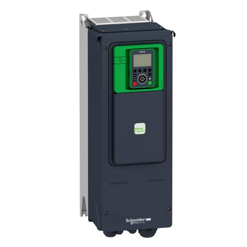
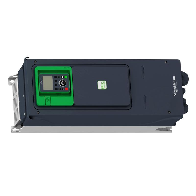
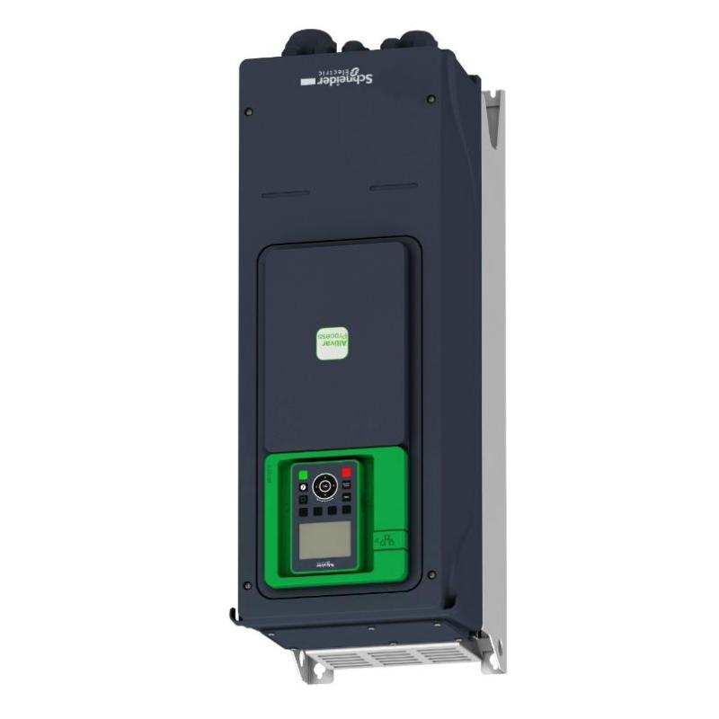
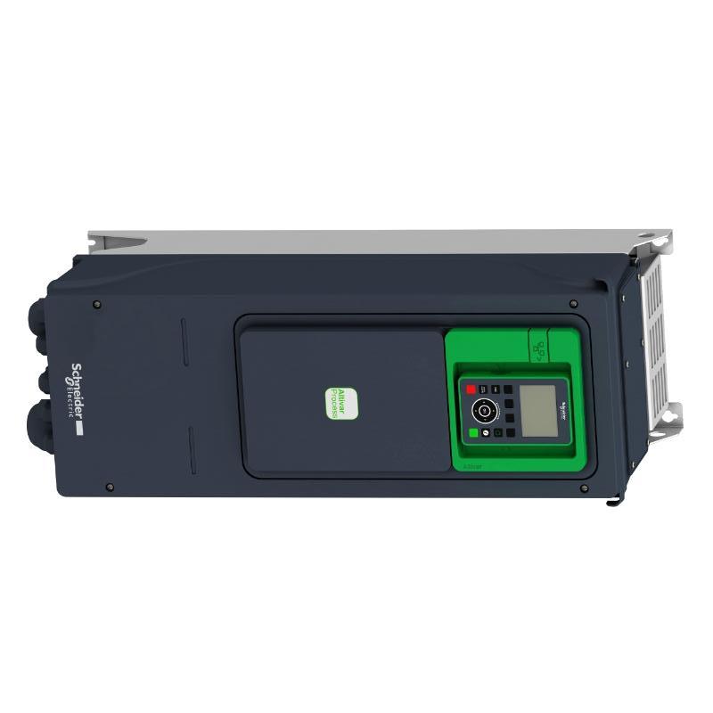
- Schneider
- ATV950U75N4
- Variable Speed Drive
- France
- 678 × 299 × 330 mm
- 13.7 kg
- Xiamen, China
- New & In Stock
- T/T, PayPal, Western Union
- 1 Year
- 1-3 Working Days
- DHL, UPS, TNT, FedEx and EMS.
- 24-Hour Service
- COO
- 5
Our advantage

Global Logistics
We have a 10-year logistics and express cooperation agreement, so our products can be shipped to any place in the world.

Brand new and original
Our products are imported in bulk from the place of origin. Because of the cooperative relationship, our products are all original and 100% new.

24-hour service
We provide 7*24 hours service to our customers. We will be there whenever you need us.

Price advantage
All our products are priced very favorably because we have our own warehouse and supply.
| Company Information | |||
| [email protected] | |||
| Mobile | +8615980777398 | ||
| +8615980777398 | |||
| 15980777398 |
Product Overview
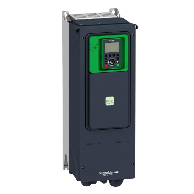
The Schneider Electric ATV950U75N4 is a 7.5 kW variable speed drive in the Altivar Process ATV900 series, used to regulate motor speed in industrial process equipment. It operates on a three-phase 380–480 V AC supply and supports synchronous and asynchronous motors. Typical applications include process pumps, ventilation systems, conveyors, and production machinery where motor speed needs to respond to changing operating conditions.
This model combines an IP55 enclosure with an integrated braking unit. In a pumping installation, for example, the drive can adjust motor speed according to pressure or flow demand from a PLC, reducing the need to operate the motor continuously at full speed. In conveyor and process machinery, adjustable acceleration and deceleration help coordinate motor operation with production sequences.
The ATV950U75N4 also supports industrial communication and embedded process-monitoring functions. These capabilities allow it to exchange operating information with automation systems while giving operators access to power consumption and drive status data.
Technical Specifications
| Parameter | Specification |
|---|---|
| Brand | Schneider Electric |
| Model | ATV950U75N4 |
| Product Type | Variable Speed Drive |
| Product Series | Altivar Process ATV900 |
| Drive Range | ATV950 |
| Rated Motor Power | 7.5 kW for normal duty |
| Rated Supply Voltage | 380–480 V AC |
| Number of Supply Phases | 3 phases |
| Rated Output Current | 16.5 A |
| Compatible Motor Types | Synchronous motors; asynchronous motors |
| Enclosure Protection | IP55 |
| Integrated Braking Unit | Yes |
| Integrated Switch | No |
| Communication Protocols | EtherNet/IP, Modbus TCP, Modbus serial |
| Mounting Method | Wall mounting |
| Dimensions | 678 × 299 × 330 mm |
| Weight | 13.7 kg |
Product Features
7.5 kW motor control: The drive regulates motor speed to match process requirements, making it suitable for equipment where operating demand varies during a production cycle.
Integrated braking unit: The braking unit supports applications that require controlled deceleration. A compatible braking resistor may be required depending on load inertia, stopping time, and braking frequency.
IP55 enclosure: The enclosure provides protection against dust ingress and water jets within the limits of its rating. Installation conditions, cable entries, temperature, and exposure to cleaning agents should be considered when selecting the mounting location.
Industrial communication: EtherNet/IP, Modbus TCP, and serial Modbus support integration with compatible PLCs and automation systems.
Embedded process monitoring: Power measurement and energy-monitoring functions help operators review consumption and operating trends. Process monitoring can also support troubleshooting when machine behavior changes.
Motor-control configuration: The drive supports synchronous and asynchronous motor applications. Correct motor data, control settings, and duty selection are necessary for the intended operating conditions.
Working Principle
The ATV950U75N4 converts incoming three-phase AC power into a controlled electrical output for the connected motor. By adjusting output voltage and frequency according to the configured control mode and speed reference, it regulates the motor’s operating speed.
In a process pumping system, a PLC may calculate the required speed from pressure or flow feedback. The drive receives that reference and adjusts the pump motor accordingly. When demand falls, the motor can run at a lower speed; when demand rises, the drive increases speed within the configured operating limits.
For equipment that must stop within a defined period, the integrated braking unit can manage energy returned by the motor during deceleration. Where resistor braking is required, the braking resistor must be selected according to the application’s energy and thermal requirements.
The drive can also exchange operating commands, status values, and fault information with the automation system. This supports coordinated control of motor-driven equipment alongside sensors, valves, other drives, and machine sequences.
Role in an Altivar Process ATV900 Control Architecture
The ATV950U75N4 acts as the motor-control layer between the plant’s electrical supply and the driven equipment. It receives operating commands from the control system, regulates motor output, and returns status information for monitoring and troubleshooting.
| Control Layer | Function | Relationship to ATV950U75N4 |
|---|---|---|
| Electrical Distribution | Supplies electrical power to the drive | Provides the required three-phase supply and upstream protection |
| Variable Speed Drive | Controls motor speed and deceleration | Adjusts motor output according to configured references and parameters |
| PLC or Process Controller | Executes process logic and machine sequences | Sends operating commands and speed references |
| HMI or Operator Panel | Displays operating values, alarms, and status | Presents drive information through the control system |
| Industrial Communication Network | Exchanges control and status data | Supports configured EtherNet/IP, Modbus TCP, or serial Modbus communication |
| Motor | Converts electrical power into mechanical motion | Operates at the speed commanded by the drive |
| Driven Equipment | Performs the industrial process | Uses motor output for pumping, ventilation, conveying, or machinery movement |
| Braking Circuit | Manages braking energy when required | Uses the integrated braking unit and a compatible resistor where necessary |
Industrial Applications
| Application | Operating Requirement | Use of the ATV950U75N4 |
|---|---|---|
| Process Pumping | Changing flow and pressure demand | Adjusts pump speed according to the process reference |
| Ventilation Systems | Airflow varies with system demand | Regulates fan speed to match operating requirements |
| Conveyor Equipment | Controlled transport speed and stopping | Coordinates motor operation with production sequences |
| Industrial Process Machinery | Motor speed follows changing process conditions | Receives commands and references from the controller |
| Material Handling | Controlled acceleration and deceleration | Supports speed regulation for the specified load profile |
| Utility Systems | Continuous motor operation with monitoring | Makes operating data available to the automation system |
| Automated Production Lines | Coordinated operation between machines | Exchanges commands and status information with the wider control architecture |
Installation and Maintenance
- Verify the complete model reference: Confirm that the unit is ATV950U75N4. This model does not have the E-suffix switch configuration, so the external isolation arrangement must suit the installation.
- Check motor ratings: Compare the motor nameplate voltage, current, power, speed, and motor type with the drive’s capabilities before commissioning.
- Confirm the supply conditions: Verify that the three-phase AC supply is within the specified 380–480 V range and that upstream electrical protection is suitable.
- Provide adequate mounting clearance: Install the drive vertically on a suitable surface and maintain the required clearances for cooling, wiring, and maintenance access.
- Review environmental conditions: Assess ambient temperature, humidity, dust, water exposure, and corrosive substances. IP55 protection should be evaluated against the actual installation environment.
- Select upstream protection: Size circuit protection and disconnecting arrangements according to the electrical installation requirements and applicable regulations.
- Separate power and control wiring: Keep motor power cables away from sensitive signal and communication wiring where practicable. Follow appropriate grounding, shielding, and EMC practices.
- Inspect motor connections: Check terminal tightness, protective-earth continuity, cable sizing, and motor wiring before energizing the drive.
- Configure motor parameters: Enter the motor nameplate data and set the control mode, acceleration and deceleration ramps, speed limits, and current limits for the application.
- Evaluate braking requirements: Determine whether the application needs a braking resistor. If required, select one based on braking energy, stopping frequency, thermal duty, and drive compatibility.
- Validate communication: Configure the selected communication protocol and verify run commands, speed references, feedback values, and fault responses during commissioning.
- Perform scheduled inspections: Check cooling passages, terminals, cables, grounding, enclosure seals, and fault history. Before internal inspection, isolate the supply and verify that the DC bus has discharged to a safe level.
Related Components
| Component | Purpose | Selection Considerations |
|---|---|---|
| Three-Phase AC Supply and Protection | Supplies power and protects the electrical circuit | Supply voltage, current capacity, fault level, and protection coordination |
| Synchronous or Asynchronous Motor | Drives the connected machinery | Motor type, rated current, power, speed, and load profile |
| Braking Resistor | Dissipates braking energy when required | Resistance, power rating, braking duty, and drive compatibility |
| PLC or Process Controller | Coordinates motor operation with the process | Control logic, supported communication protocol, and feedback requirements |
| HMI or Operator Panel | Displays operating values and alarms | Interface requirements and compatibility with the control system |
| Industrial Ethernet Switch | Connects networked automation devices | Network topology, port requirements, and industrial environment |
| Motor Cable | Connects the drive output to the motor | Current rating, cable length, insulation, shielding, and EMC requirements |
| EMC Accessories | Helps manage electromagnetic interference | Supply characteristics, cable arrangement, and installation conditions |
Recommended Related Models
| Model | Product Description | Application Context |
|---|---|---|
| ATV950U55N4 | Altivar Process ATV950 Variable Speed Drive, 5.5 kW class | For applications with lower motor-power requirements |
| ATV950U75N4E | Altivar Process ATV950 Variable Speed Drive, 7.5 kW class | Same nominal power class with an integrated switch configuration |
| ATV950D11N4 | Altivar Process ATV950 Variable Speed Drive, 11 kW class | For applications requiring a higher motor-power class |
| ATV930U75N4 | Altivar Process ATV930 Variable Speed Drive, 7.5 kW class | An alternative within the ATV900 family for applications whose enclosure and feature requirements suit the ATV930 range |
Model selection should account for motor current, duty profile, enclosure protection, braking needs, communication interfaces, and the electrical isolation arrangement. Similar power ratings do not automatically mean that two models are interchangeable.
Key Advantages
- 7.5 kW motor control: Supports process equipment requiring adjustable motor speed.
- Integrated braking unit: Supports controlled deceleration when the braking arrangement is correctly selected.
- Industrial network connectivity: Integrates with compatible PLCs and supervisory systems.
- Process monitoring: Helps operators review energy use and drive operating conditions.
- IP55 enclosure: Supports installation in a range of industrial environments within the specified protection limits.
Technical FAQs
What is the rated output current of the ATV950U75N4?
The model is listed with a rated output current of 16.5 A. Final selection should also account for the motor’s nameplate current, duty profile, supply conditions, and application requirements.
Does the ATV950U75N4 include an integrated disconnect switch?
No. The ATV950U75N4 is the version without the E-suffix switch configuration. The electrical installation must include an appropriate isolation arrangement to meet applicable requirements.
When is a braking resistor needed with the ATV950U75N4?
A braking resistor may be needed when the load returns significant energy during deceleration or when the machine requires frequent or rapid stopping. Selection depends on load inertia, stopping time, braking frequency, and the drive’s permitted braking arrangement.
How can the ATV950U75N4 communicate with a PLC?
The drive supports EtherNet/IP, Modbus TCP, and serial Modbus. The communication settings, network topology, and control mapping must match the PLC and the intended application.