

ProductPRODUCT
Featured products
Contact Us
- Schneider
- ATV950U55N4
- Variable Speed Drive
- France
- 678 × 264 × 272 mm
- 10.7 kg
- Xiamen, China
- New & In Stock
- T/T, PayPal, Western Union
- 1 Year
- 1-3 Working Days
- DHL, UPS, TNT, FedEx and EMS.
- 24-Hour Service
- COO
- 6
Our advantage

Global Logistics
We have a 10-year logistics and express cooperation agreement, so our products can be shipped to any place in the world.

Brand new and original
Our products are imported in bulk from the place of origin. Because of the cooperative relationship, our products are all original and 100% new.

24-hour service
We provide 7*24 hours service to our customers. We will be there whenever you need us.

Price advantage
All our products are priced very favorably because we have our own warehouse and supply.
| Company Information | |||
| [email protected] | |||
| Mobile | +8615980777398 | ||
| +8615980777398 | |||
| 15980777398 |
Product Overview
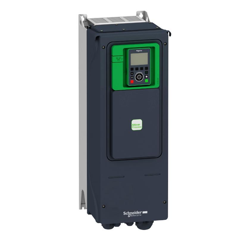
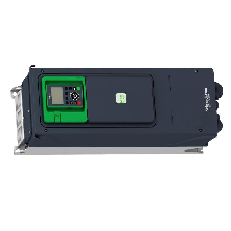
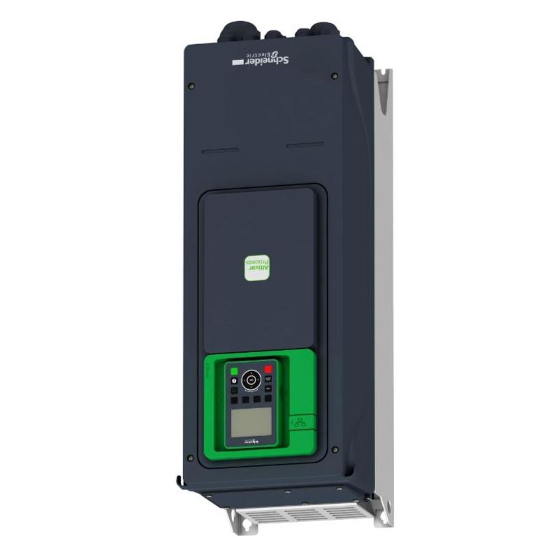
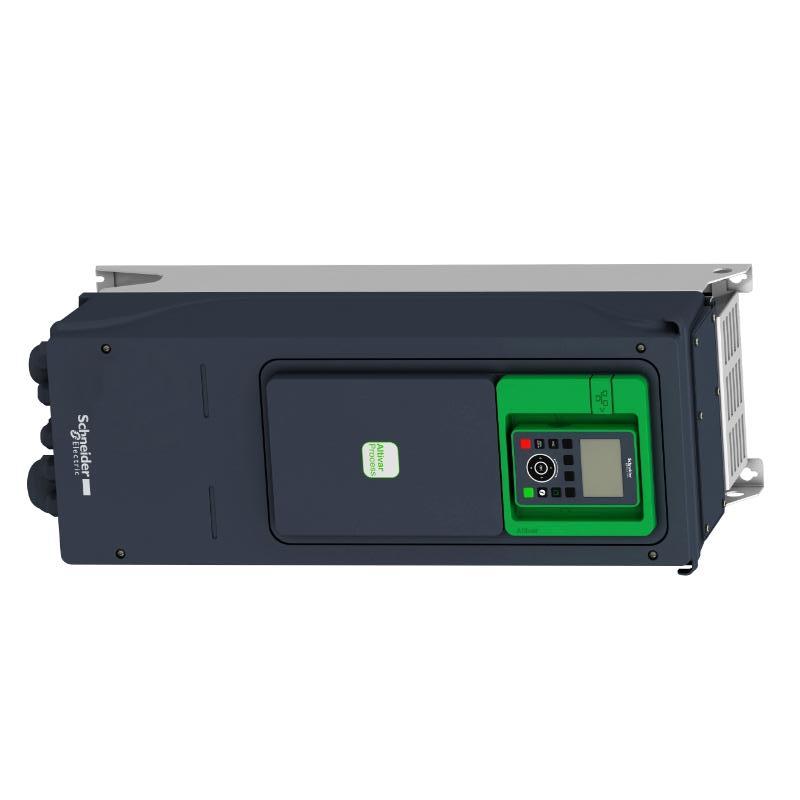
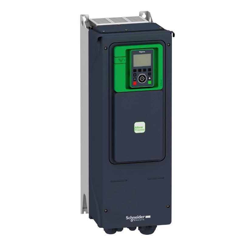
The Schneider ATV950U55N4 is a 5.5 kW variable speed drive from the Altivar Process ATV900 family. It operates on a 400/480 V three-phase supply and features an IP55 enclosure and an integrated braking unit. It is intended for industrial motor-control applications where speed adjustment, process regulation, and equipment monitoring are required.
In a pumping station, the drive can adjust motor speed as flow demand changes, helping the system avoid running continuously at full speed when the process requires less output. On a fan or conveyor, it can control acceleration and deceleration to suit operating conditions and reduce unnecessary mechanical stress. The braking unit is relevant when the application requires controlled deceleration and the braking system has been configured for the load.
The ATV950 range combines motor control with process-oriented monitoring functions. Embedded features include power measurement, an energy dashboard, process monitoring and control, asset monitoring and protection, and drift monitoring. These functions can help operators review drive behavior and identify changes in process conditions without treating the drive as merely a speed controller.
The U55 designation identifies the 5.5 kW power rating, while N4 identifies the 400/480 V IP55 version with a braking unit. The model does not carry the E suffix used for the corresponding switch-equipped configuration. This distinction matters when replacing an installed drive because switching and isolation arrangements may differ even when the power rating is the same.
Before replacing an existing unit, check the motor nameplate, supply voltage, required braking behavior, enclosure conditions, control wiring, and communication setup. A drive with a matching kilowatt rating is not necessarily a direct replacement if the installation uses different switching or control arrangements.
Technical Specifications
| Parameter | Specification |
|---|---|
| Manufacturer | Schneider Electric |
| Model | ATV950U55N4 |
| Product Family | Altivar Process ATV900 |
| Product Type | Variable Speed Drive |
| Rated Motor Power | 5.5 kW |
| Supply Voltage Class | 400/480 V AC |
| Supply Phase | Three-phase |
| Braking Unit | Included |
| Switching Configuration | Without the E-suffix switch configuration |
| Degree of Protection | IP55 |
| Dimensions | 678 × 264 × 272 mm |
| Weight | 10.7 kg |
| Embedded Functions | Power measurement, energy dashboard, process monitoring and control, asset monitoring and protection, drift monitoring |
Product Features
- 5.5 kW motor control: Suitable for compatible industrial motors operating within the drive’s specified limits.
- 400/480 V three-phase supply: Fits industrial power systems within the applicable voltage range.
- IP55 enclosure: Provides protection against dust ingress and water jets under the conditions defined by the enclosure rating.
- Integrated braking unit: Supports applications requiring braking capability, subject to the selected braking arrangement and operating duty.
- Process-oriented monitoring: Includes functions for monitoring drive and process conditions.
- Power measurement: Makes electrical operating information available for energy and performance review.
- Energy dashboard: Helps operators assess energy-related operating data.
- Asset monitoring and protection: Supports observation of operating conditions relevant to equipment maintenance.
- Drift monitoring: Helps identify changes in process behavior that may warrant investigation.
- Industrial motor-speed regulation: Allows motor output to follow configured references instead of operating only at a fixed supply frequency.
Working Principle
The ATV950U55N4 controls an AC motor by adjusting the electrical output supplied to it. The drive’s power electronics convert the incoming three-phase supply into a controlled output, allowing motor speed and acceleration to be regulated according to the selected control method and operating reference.
The basic power path is:
Three-Phase AC Supply → ATV950U55N4 → Controlled AC Output → Motor → Driven Equipment
For a pump, the drive can receive a speed reference from a controller or a configured process-control function. When demand changes, the motor speed can be adjusted, changing pump output to suit the required flow or pressure. A fan, conveyor, or other compatible load can use a similar arrangement, although its control settings depend on the machine’s operating characteristics.
Acceleration and deceleration settings determine how quickly the motor follows a new reference. The integrated braking unit supports the specified braking arrangement when the application requires energy management during deceleration. The braking capability and any associated components must be matched to the actual load and stopping duty.
The drive’s monitoring functions provide operating information alongside motor control. In a complete installation, sensors, PLC logic, and supervisory interfaces may supply references, process feedback, alarms, and operating commands. The drive handles motor control, while the wider automation system determines how that control responds to the process.
Role in an Altivar Process ATV900 Motor Control Architecture
The ATV950U55N4 is the motor-control element between the industrial power supply and the driven machine. It regulates motor output and exchanges operating information with the control system when the required interfaces are configured.
| System Element | Function |
|---|---|
| ATV950U55N4 Variable Speed Drive | Controls motor speed and provides drive-level monitoring functions |
| Three-Phase AC Supply | Supplies electrical power to the drive |
| Upstream Circuit Breaker | Provides circuit protection and supports isolation according to the installation design |
| AC Motor | Converts electrical energy into mechanical rotation and torque |
| Braking Arrangement | Handles braking energy according to the drive configuration and application duty |
| Process Sensor | Measures a process variable such as pressure, flow, or temperature |
| PLC or Process Controller | Coordinates process logic and supplies commands or references |
| HMI or Supervisory Interface | Displays operating information and allows authorized operator interaction |
| Industrial Communication Network | Exchanges commands, status, and process data where the required interface is configured |
The actual system arrangement depends on the motor, load, protection design, control method, and communication requirements. The absence of the E suffix should be considered when checking how the drive is switched and isolated within the installation.
Industrial Applications
| Application | Typical Use |
|---|---|
| Industrial Pumping | Adjusting pump speed to meet changing flow or pressure demand |
| HVAC Fans and Blowers | Regulating airflow through motor-speed control |
| Water and Wastewater Systems | Controlling compatible pumps and other fluid-handling equipment |
| Conveyor Systems | Managing motor speed and acceleration according to material-handling requirements |
| Process Machinery | Regulating motor-driven equipment in continuous production |
| Industrial Mixing | Adjusting mixer speed to suit process and load conditions |
| Manufacturing Lines | Coordinating motor operation with production sequences |
| Utility Equipment | Controlling compatible auxiliary motors in industrial facilities |
| Machinery Retrofit Projects | Adding variable-speed control where the motor and driven load permit it |
| Process Monitoring Installations | Using drive operating data to support maintenance and process assessment |
Installation and Maintenance
- Verify the complete model reference: Confirm ATV950U55N4 and distinguish it from the switch-equipped ATV950U55N4E configuration.
- Check the motor nameplate: Verify rated voltage, current, frequency, speed, and other required motor data before configuring the drive.
- Confirm supply compatibility: Ensure that the incoming three-phase supply falls within the drive’s permitted operating range.
- Inspect the mounting location: Confirm that the mounting surface supports the drive and that the environment is suitable for an IP55 installation.
- Maintain cooling clearance: Follow the specified mounting orientation and clearance requirements to allow heat to dissipate correctly.
- Preserve enclosure protection: Check cable entries, seals, enclosure closures, and mounting interfaces so the installation does not compromise the IP55 rating.
- Verify upstream protection: Confirm that breakers, conductors, earthing, and other protective devices are coordinated with the drive installation.
- Inspect power and control wiring: Check terminal connections, conductor sizing, cable routing, and separation of power and control circuits.
- Check the braking requirements: Confirm that the integrated braking unit and associated arrangement suit the load inertia and required deceleration duty.
- Configure motor-control parameters: Set the motor data, speed reference, acceleration and deceleration times, operating limits, and selected control method.
- Test the complete operating sequence: Verify start and stop commands, reference response, process feedback, fault handling, and braking behavior before returning the equipment to service.
- Record commissioning information: Document the motor data, drive settings, protection devices, communication setup, and baseline operating values for future troubleshooting.
Related Components
| Component | Function |
|---|---|
| Three-Phase AC Motor | Provides the mechanical output regulated by the drive |
| Upstream Circuit Breaker | Protects the incoming circuit and supports safe isolation according to the system design |
| Line Contactor, Where Required | Provides switching as specified by the overall motor-control design |
| Braking Resistor, Where Required | Dissipates braking energy when required by the application and braking configuration |
| Pressure or Flow Sensor | Supplies process feedback for suitable closed-loop control applications |
| PLC or Process Controller | Coordinates drive commands with machine or process logic |
| HMI | Displays operating values, alarms, and drive status |
| Industrial Communication Network | Transfers control and monitoring data when the relevant interface is configured |
Recommended Related Models
| Model | Product Type | Typical Application |
|---|---|---|
| Schneider ATV950U40N4 | Altivar Process ATV950 Variable Speed Drive | 4 kW configuration with 400/480 V supply, IP55 enclosure, and braking unit |
| Schneider ATV950U75N4 | Altivar Process ATV950 Variable Speed Drive | 7.5 kW configuration for compatible applications requiring a higher motor-power rating |
| Schneider ATV950U55N4E | Altivar Process ATV950 Variable Speed Drive | 5.5 kW configuration with the switch-equipped arrangement |
| Schneider ATV930U55N4 | Altivar Process ATV930 Variable Speed Drive | Related 5.5 kW drive in the ATV900 family for applications where the ATV930 configuration meets system requirements |
These models have different power ratings or configuration details and should not be treated as automatic substitutes. Verify motor current, supply voltage, braking requirements, enclosure rating, switching and isolation arrangements, control interfaces, and mounting dimensions before selecting an alternative.
Key Advantages
- Regulates motor speed to match changing process demand.
- Combines a 5.5 kW rating with a 400/480 V three-phase supply class.
- Uses an IP55 enclosure for suitable industrial environments.
- Includes an integrated braking unit.
- Provides embedded power measurement and process monitoring functions.
- Supports drive-level operating review and maintenance assessment.
Technical FAQs
What is the difference between ATV950U55N4 and ATV950U55N4E?
Both models belong to the ATV950 range and have a 5.5 kW rating, 400/480 V supply class, IP55 enclosure, and braking unit. The E suffix identifies the switch-equipped configuration. The distinction is important when matching the drive to an existing switching and isolation arrangement.
Can the ATV950U55N4 control a pump based on pressure feedback?
The drive can regulate pump speed, and a suitable control arrangement can use pressure feedback to adjust that speed. The complete function depends on the configured control strategy, sensor signal, setpoint, and drive or PLC parameters.
What should be checked if the motor trips during acceleration?
Review the recorded fault, motor nameplate settings, acceleration ramp, current limit, mechanical load, supply condition, and motor wiring. Excessive load, unsuitable ramp settings, incorrect motor data, or an electrical problem can all contribute to acceleration-related trips.
Does IP55 mean the drive can be installed in any outdoor location?
No. IP55 defines protection against dust ingress and water jets under specified test conditions. Ambient temperature, direct weather exposure, condensation, solar heating, corrosion, and mounting clearances still need to be considered for the intended installation.