

ProductPRODUCT
Featured products

Contact Us
- Ingersoll Rand
- 47627051001 22832885
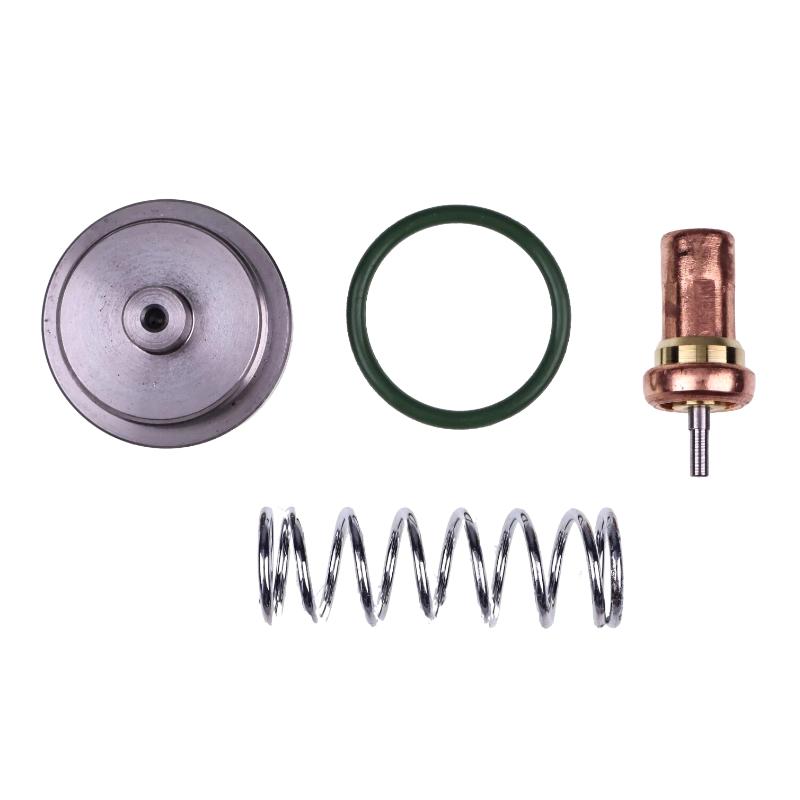
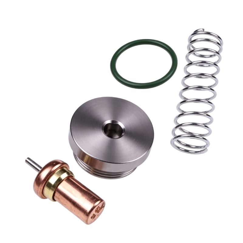
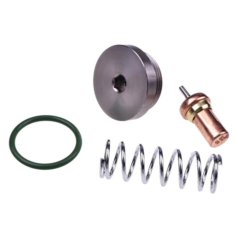
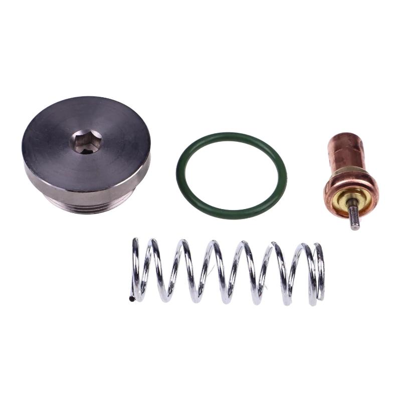
- Thermal Valve Kit
- USA
- 100 × 15 × 80 mm
- 0.15 kg
- Xiamen, China
- New & In Stock
- T/T, PayPal, Western Union
- 1 Year
- 1-3 Working Days
- DHL, UPS, TNT, FedEx and EMS.
- 24-Hour Service
- COO
- 6
Our advantage

Global Logistics
We have a 10-year logistics and express cooperation agreement, so our products can be shipped to any place in the world.

Brand new and original
Our products are imported in bulk from the place of origin. Because of the cooperative relationship, our products are all original and 100% new.

24-hour service
We provide 7*24 hours service to our customers. We will be there whenever you need us.

Price advantage
All our products are priced very favorably because we have our own warehouse and supply.
| Company Information | |||
| [email protected] | |||
| Mobile | +8615980777398 | ||
| +8615980777398 | |||
| 15980777398 |
Product Overview
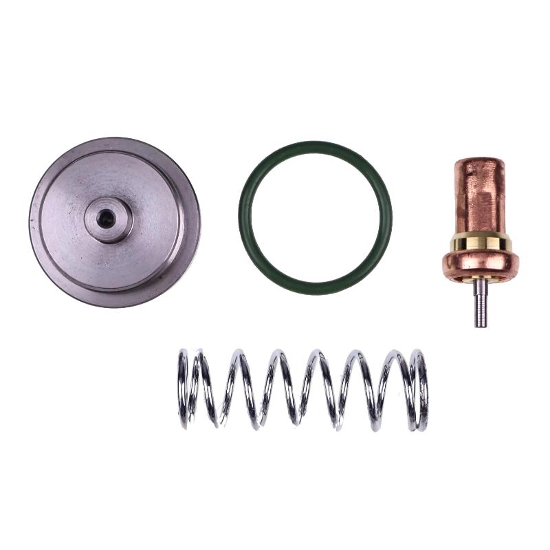
The Ingersoll Rand 47627051001 22832885 Thermal Valve Kit is a service kit for the oil temperature regulation system in compatible rotary screw air compressors. The thermal valve controls the route taken by lubricating oil according to its temperature, determining when oil should circulate through the cooling circuit and when it should bypass the cooler.
In an oil-injected screw compressor, lubricant performs several jobs simultaneously. It reduces friction between the screw elements and associated components, helps seal the compression chamber, and carries away heat generated during compression. The oil must therefore circulate through the correct path as the compressor moves from a cold start to sustained operation.
When the oil is relatively cool, the thermal valve keeps the cooling path partially or fully bypassed, depending on the valve design. As the oil temperature rises, its temperature-responsive element changes position and allows more oil to flow through the cooler. The cooled oil then returns to the lubrication circuit, helping the compressor maintain its intended operating temperature.
A thermal valve that sticks in the bypass position can prevent sufficient oil from reaching the cooler. The compressor may then experience rising oil temperature, high-temperature alarms, or thermal shutdowns during extended operation. If the valve remains in the cooling position when the oil is still cold, the compressor may take longer to reach its normal operating temperature.
The 22832885 kit is associated with selected Ingersoll Rand UP6 rotary screw compressor configurations, including certain UP6-20, UP6-25, and UP6-30 machines. Related equipment versions may use different part references, so the installed valve configuration must be checked before replacement. The kit is intended to service the compatible thermal valve mechanism rather than automatically replace the complete valve housing or the entire oil cooling system.
For maintenance engineers, the important diagnostic distinction is between a valve that fails to regulate oil flow and a cooling system that cannot remove enough heat. A dirty cooler, restricted oil filter, incorrect oil level, or cooling fan problem can produce similar temperature symptoms. Identifying the actual cause before replacing parts helps avoid unnecessary work and repeat shutdowns.
Technical Specifications
| Parameter | Specification |
|---|---|
| Manufacturer | Ingersoll Rand |
| Model Reference | 47627051001 |
| Part Number | 22832885 |
| Product Type | Thermal Valve Kit |
| Product Category | Rotary Screw Air Compressor Spare Part |
| Primary Function | Regulation of lubricating oil flow according to temperature |
| Main System | Compressor lubrication and oil cooling circuit |
| Installation Location | Thermal valve assembly within the compressor oil circuit |
| Operating Principle | Temperature-responsive oil flow regulation |
| Cold-Start Function | Controls oil routing during compressor warm-up |
| Cooling Function | Directs oil through the cooler when required |
| Maintenance Purpose | Servicing the compatible thermal valve mechanism |
| Associated Equipment | Selected Ingersoll Rand UP6 compressor configurations |
| Compatibility Requirement | Confirm the compressor model and installed valve configuration |
| Dimensions | 100 × 15 × 80 mm |
| Weight | 0.15 kg |
Product Features
- Temperature-responsive regulation: Changes the oil flow path as the lubricant warms during compressor operation.
- Cooling circuit control: Supports the routing of oil through the cooler when additional heat removal is required.
- Cold-start oil management: Helps maintain the intended bypass arrangement while the oil is below its normal operating temperature.
- Thermal valve servicing: Supports repair of the compatible valve mechanism using the specified kit components.
- Actuator and seal maintenance: The kit contents may include temperature-responsive and sealing components; the exact parts should be verified before service.
- Overtemperature troubleshooting: Relevant when inspection identifies a sticking or malfunctioning thermal valve as the cause of excessive oil temperature.
- Lubrication system support: Helps maintain the intended oil circulation arrangement within the compressor.
- Configuration identification: The 22832885 part number provides a defined reference for replacement planning and maintenance records.
- Targeted component repair: Allows servicing of applicable valve components without automatically replacing the complete assembly.
- Preventive maintenance application: Can be included in scheduled maintenance when inspection or operating history indicates that the valve requires attention.
Working Principle
The thermal valve regulates oil temperature indirectly by controlling the route through which the lubricant circulates. Rather than cooling the oil itself, it changes the distribution between the bypass path and the oil cooler.
Compressor Air End → Oil Separation Circuit → Thermal Valve → Oil Cooler or Bypass Path → Lubrication Circuit → Compressor Air End
During a cold start, the oil temperature is below the valve’s operating threshold. The temperature-responsive element holds the valve in a position that limits cooling, allowing the lubricant to warm as the compressor runs. The exact bypass arrangement depends on the internal valve design.
As the oil heats up, the thermal element responds to the rising temperature and progressively changes the valve position. More oil can then pass through the cooler, where heat is transferred to the surrounding cooling air or another cooling medium, depending on the compressor package.
After cooling, the oil returns to the lubrication circuit and continues circulating through the compressor. The valve repeatedly adjusts the flow distribution in response to temperature changes, helping balance the need for warm-up against the need to remove excess heat during sustained operation.
If the temperature-responsive element fails to move correctly, the oil may continue bypassing the cooler even when cooling is required. The resulting temperature rise can trigger an alarm or shutdown. Conversely, a valve that sends too much oil through the cooler during warm-up can delay the compressor from reaching its normal operating condition.
The 22832885 kit is relevant when the fault has been traced to serviceable components within the compatible thermal valve assembly. Before installation, technicians should verify the kit contents and inspect the valve body and seating surfaces. Damage to components not included in the kit may require a different repair approach.
Role in an Ingersoll Rand Compressor Lubrication System
The thermal valve manages the relationship between oil circulation and heat removal. It sits within the lubrication circuit and determines how oil is distributed between the cooler and bypass route as operating temperature changes.
Oil Separation and Recovery → Thermal Valve → Cooling or Bypass Path → Oil Filter and Lubrication Circuit → Compressor Air End
| System Component | Function |
|---|---|
| 22832885 Thermal Valve Kit | Services the compatible temperature-responsive valve mechanism |
| Thermal Valve Assembly | Regulates the distribution of oil between cooling and bypass paths |
| Compressor Lubricating Oil | Lubricates internal components and carries away compression heat |
| Oil Cooler | Removes heat from circulating lubricant |
| Oil Filter | Removes contaminants from the lubrication circuit |
| Oil Separator Element | Separates entrained oil from compressed air |
| Oil Return Circuit | Returns recovered oil toward the compressor lubrication system |
| Cooling Fan | Moves air through the cooler in fan-cooled configurations |
| Temperature Sensor | Monitors oil or system temperature where fitted |
| Compressor Controller | Monitors operating conditions and manages alarms or shutdowns |
| Pressure Monitoring Devices | Provide operating information used during system diagnosis |
A thermal valve repair addresses oil flow distribution, but the overall temperature result also depends on cooler condition, airflow, oil quality, and unobstructed circulation through the lubrication circuit.
Industrial Applications
| Application | Typical Use |
|---|---|
| General Manufacturing | Maintaining oil temperature regulation in compressors supplying pneumatic production equipment |
| Automotive Production | Servicing thermal valves in compressors supporting assembly lines and workshop utilities |
| Metalworking Facilities | Addressing oil temperature faults in compressors serving machine tools and pneumatic machinery |
| Packaging Plants | Maintaining lubrication temperature control during changing production loads |
| Plastics Processing | Supporting thermal management in compressors supplying production equipment |
| Textile Manufacturing | Maintaining oil circulation and cooling performance in compressors operating over extended shifts |
| Central Compressor Rooms | Servicing thermal valve assemblies in shared compressed air installations |
| Industrial Assembly | Addressing valve-related overheating in compressors supplying air-powered tools |
| Continuous-Duty Operations | Maintaining oil temperature regulation during sustained compressor operation |
| Preventive Maintenance Programs | Replacing worn thermal valve components when inspection identifies a fault |
The required service frequency depends on operating conditions, oil temperature history, cooler cleanliness, and the condition of the valve mechanism. A high-temperature alarm should prompt inspection of the complete cooling and lubrication system rather than an automatic assumption that the thermal valve has failed.
Installation and Maintenance
- Verify the part reference: Confirm 47627051001 and 22832885 against the compressor’s parts documentation and installed thermal valve configuration.
- Isolate the compressor: Stop the machine, disconnect the required electrical supply, and follow the site’s lockout and tagout procedure.
- Depressurize the relevant circuit: Release stored pressure according to the compressor service procedure before opening any oil system connections.
- Allow the oil to cool: Wait until the lubricant and surrounding components reach a safe temperature for maintenance.
- Record the original arrangement: Note the valve orientation, component positions, and oil passage connections before disassembly.
- Inspect the valve housing: Check the bore, seating surfaces, and mounting interfaces for contamination, wear, corrosion, or damage.
- Verify the kit contents: Compare the supplied parts with the applicable parts list before removing the existing thermal valve components.
- Examine the temperature-responsive element: Check the relevant actuator, spring, seals, and other supplied components for damage or deterioration.
- Clean the service area: Prevent dirt and foreign material from entering the oil circuit during disassembly and reassembly.
- Install the replacement components: Follow the applicable service procedure for component orientation, seal placement, and tightening requirements.
- Verify temperature regulation: After reassembly and an approved restart, monitor the oil temperature as the compressor warms up and operates under load.
- Record the service results: Document the installed kit reference, identified fault, replaced components, and operating temperature observations.
If the compressor continues to run hot after the thermal valve has been serviced, inspect the oil cooler, cooling fan, oil filter, oil level, and oil circulation path. Confirm that temperature readings are accurate before attributing continued overheating to the repaired valve.
Related Components
| Component | Function |
|---|---|
| Ingersoll Rand 22832885 | Thermal valve service kit for compatible compressor configurations |
| Thermal Valve Assembly | Controls the oil flow distribution according to temperature |
| Oil Cooler | Removes heat from circulating lubricating oil |
| Compressor Oil Filter | Removes contaminants from the lubrication circuit |
| Compressor Lubricating Oil | Provides lubrication and carries heat away from the air end |
| Oil Separator Element | Separates oil from compressed air |
| Oil Return Line | Returns recovered oil to the lubrication circuit |
| Cooling Fan Assembly | Supplies airflow through the cooler in applicable configurations |
| Temperature Sensor | Monitors oil or system temperature where fitted |
| Oil Circuit Seals | Help prevent leakage at serviceable oil circuit connections |
Recommended Related Models
| Model / Product Reference | Product Type | Typical Application |
|---|---|---|
| Ingersoll Rand 22832885 | Thermal Valve Kit | Servicing the specified thermal valve assembly |
| Ingersoll Rand 22064687 | Thermal Valve Kit | Earlier thermal valve part reference; verify supersession and fitment for the installed compressor |
| Ingersoll Rand 22393326 | Thermal Valve Kit | Related part reference associated with the 22832885 replacement reference |
| Ingersoll Rand UP6-20 | Rotary Screw Air Compressor | Thermal valve maintenance in compatible configurations |
| Ingersoll Rand UP6-25 | Rotary Screw Air Compressor | Oil temperature control maintenance where the parts list specifies the kit |
| Ingersoll Rand UP6-30 | Rotary Screw Air Compressor | Thermal valve servicing subject to configuration verification |
| Ingersoll Rand UP6S Series | Rotary Screw Air Compressor | Thermal valve maintenance where the installed assembly matches |
| Ingersoll Rand Oil Cooler Assembly | Compressor Cooling Component | Removes heat from circulating lubricant |
| Ingersoll Rand Oil Filter Element | Compressor Oil Filtration Component | Filters oil before it returns to the lubrication circuit |
Key Advantages
- Supports repair of the thermal valve mechanism in compatible compressor configurations.
- Helps restore temperature-responsive oil flow when internal valve components are faulty.
- Supports the transition between cold-start bypass and operating-temperature cooling.
- Helps address valve-related overheating and abnormal warm-up behavior.
- Allows targeted servicing without automatically replacing the complete valve assembly.
- Provides a defined part number for maintenance planning and service records.
Technical FAQs
How does the thermal valve differ from the minimum pressure valve?
The thermal valve regulates oil flow according to temperature, controlling whether lubricant passes through the cooler or follows a bypass path. The minimum pressure valve maintains pressure within the separator system and helps prevent reverse airflow. They serve different functions and should not be treated as interchangeable components.
Can a thermal valve cause repeated high-temperature shutdowns?
Yes. If the valve remains in a position that prevents sufficient oil from reaching the cooler, compressor temperature can rise during operation. However, restricted cooler airflow, a dirty cooler, inadequate oil circulation, or an incorrect temperature reading can produce similar symptoms and should be investigated.
What components are included in the 22832885 Thermal Valve Kit?
The kit is associated with internal thermal valve service components, which may include a temperature-responsive actuator, spring, seals, and retaining parts. The exact contents should be verified against the applicable kit specification before maintenance because the supplied components determine which parts of the valve can be serviced.
Is the 22832885 kit compatible with every Ingersoll Rand UP6 compressor?
No universal fitment should be assumed from the UP6 series name alone. The kit is associated with selected UP6-20, UP6-25, and UP6-30 configurations and certain earlier UP6S versions. Confirm the compressor identification, installed thermal valve, and applicable parts reference before selecting the replacement kit.