

ProductPRODUCT
Featured products
Contact Us
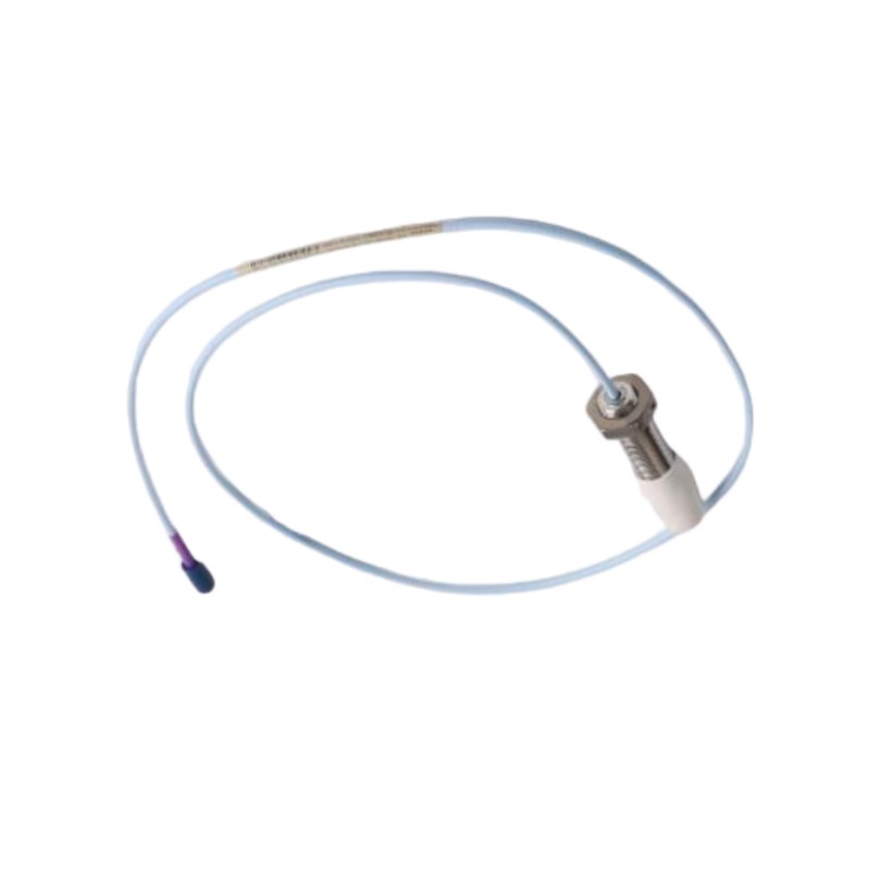
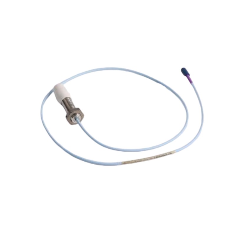
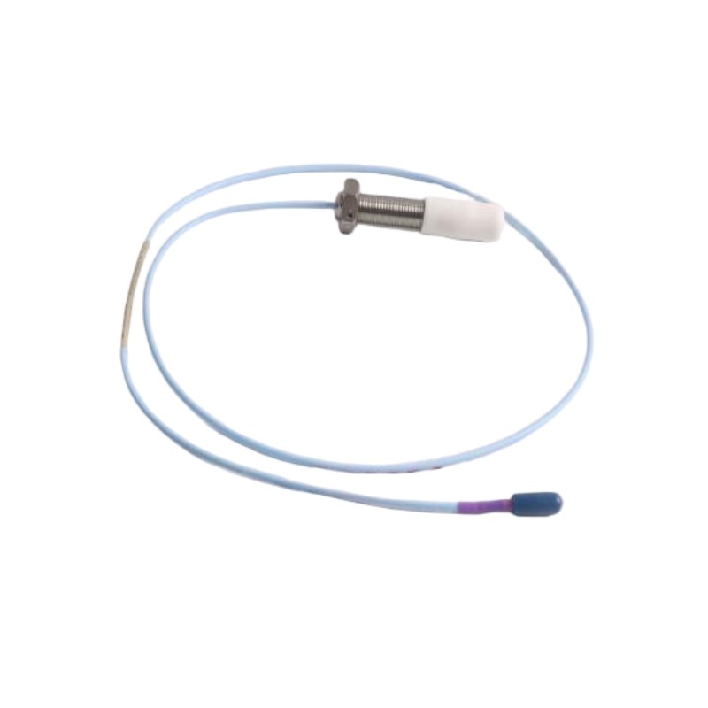
- Bently Nevada
- 330709-000-050-10-11-00
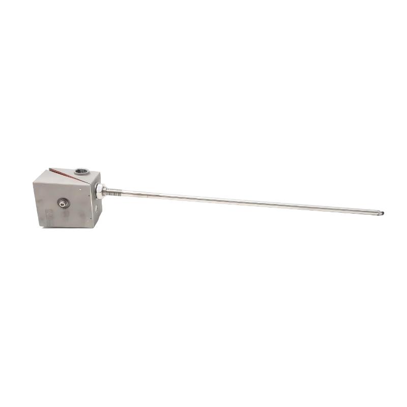
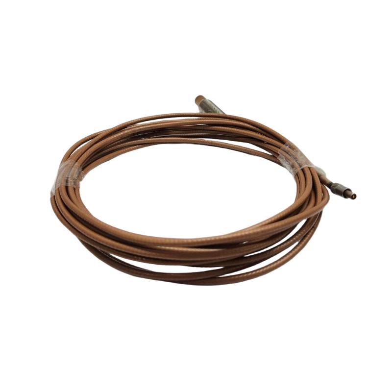
- 3300 XL 11mm Proximity Probe
- USA
- 50 mm
- 2kg
- Xiamen, China
- New & In Stock
- T/T, PayPal, Western Union
- 1 Year
- 1-3 Working Days
- DHL, UPS, TNT, FedEx and EMS.
- 24-Hour Service
- COO
- 3
Our advantage

Global Logistics
We have a 10-year logistics and express cooperation agreement, so our products can be shipped to any place in the world.

Brand new and original
Our products are imported in bulk from the place of origin. Because of the cooperative relationship, our products are all original and 100% new.

24-hour service
We provide 7*24 hours service to our customers. We will be there whenever you need us.

Price advantage
All our products are priced very favorably because we have our own warehouse and supply.
| Company Information | |||
| [email protected] | |||
| Mobile | +8615980777398 | ||
| +8615980777398 | |||
| 15980777398 |
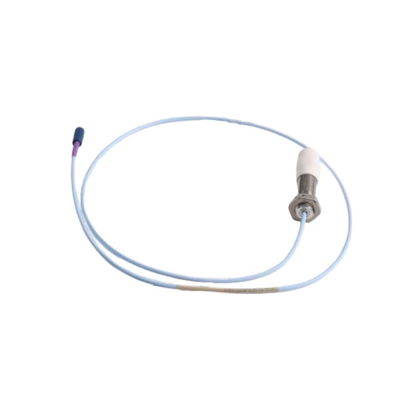
Bently Nevada 330709-000-050-10-11-00 Proximity Probe: Technical Specifications, Product Description, Applications, Advantages, and Related Models
1. Product Overview
The Bently Nevada 330709-000-050-10-11-00 is a model identified within the 3300 XL 11 mm proximity probe family. Proximity probes of this type are designed for non-contact measurement of the distance between a sensor tip and a conductive target, commonly a rotating shaft in industrial machinery.
The probe is intended to operate as part of a compatible measurement system. When correctly installed and paired with suitable signal-conditioning electronics, it can provide measurements used to monitor shaft vibration, relative displacement, and other forms of mechanical movement.
The model number contains several configuration fields relating to the probe’s mechanical dimensions, cable arrangement, connector, and approval options. These details are important when selecting a spare part, replacing an existing probe, or checking compatibility with installed monitoring equipment.
Configuration note: the suffix 11 differs from the 02 connector configuration discussed in earlier models. Its precise meaning and compatibility should be confirmed against the product’s configuration documentation before purchase. It should not be assumed to have the same connector arrangement as a model ending in 02.
2. Brand and Product Series
| Item | Description |
|---|---|
| Brand | Bently Nevada |
| Product series | 3300 XL 11 mm |
| Model | 330709-000-050-10-11-00 |
| Product category | Industrial proximity probe |
| Sensing principle | Eddy-current proximity sensing |
| Primary function | Non-contact shaft displacement and vibration measurement |
| Mounting thread | M16 × 1.5, subject to confirmation against the exact model drawing |
| Case-length option | 50 mm, subject to confirmation against the exact model drawing |
| Cable-length option | Code 10; commonly associated with a 1.0 m system cable configuration, but verify the exact code definition |
| Connector/cable option | Code 11; confirm the precise connector and cable arrangement before ordering |
| Approval suffix | 00; optional agency-approval package not specified |
| Typical application | Compatible industrial machinery monitoring systems |
The probe is a sensing component rather than a complete monitoring system. It needs the correct signal-conditioning hardware and monitoring equipment to convert its sensing response into usable measurements.
3. Correct Interpretation of the Model Number
For this model, the cable-length code is 10, which indicates 1.0 metre, not 5.0 metres. The connector and cable code 11 identifies a miniature ClickLoc coaxial connector with a connector protector and FluidLoc cable. The final 00 indicates that optional agency approvals are not requested.
| Code segment | Meaning | Configuration |
|---|---|---|
| 330709 | Base probe model | 3300 XL 11 mm, M16 × 1.5 thread, unarmored probe |
| 000 | Unthreaded-length option | 0 mm |
| 050 | Overall case-length option | 50 mm |
| 10 | Total cable length | 1.0 m |
| 11 | Connector and cable option | Miniature ClickLoc coaxial connector with protector and FluidLoc cable |
| 00 | Agency approval option | Not required |
4. Main Technical Characteristics
The following characteristics describe the 3300 XL 11 mm probe family and its typical installation requirements. Model-specific values should be checked against the applicable drawing before use in formal engineering documents.
| Technical item | Description |
|---|---|
| Sensing method | Eddy-current proximity sensing |
| Nominal probe-tip diameter | Approximately 10.7 mm maximum |
| Thread | M16 × 1.5 |
| Case length | 50 mm |
| Unthreaded length | 0 mm |
| Cable length | 1.0 m |
| Cable type | FluidLoc |
| Connector | Miniature coaxial ClickLoc with connector protector |
| Typical probe-tip material | PPS |
| Typical case material | AISI 304 stainless steel |
| Cable construction | 75 Ω triaxial cable with FEP insulation, subject to exact configuration |
| Minimum cable bend radius | Approximately 25.4 mm for the applicable cable configuration |
| Recommended case torque | Approximately 21.1 N·m for the applicable installation |
| Temperature range | Confirm the exact limits for the delivered probe and complete system |
| Product dimensions | M16 × 1.5 thread; 50 mm case; 1.0 m cable; refer to the drawing for all other dimensions |
| Product weight (kg) | Exact weight not confirmed for this model |
| Shipping weight (kg) | Must be confirmed for the actual packaged item |
The 50 mm case length is not the same as the complete installed length. The probe also has a cable and connector, and the final dimensions depend on the specific mechanical configuration. The product’s own mass should likewise be distinguished from shipping weight, which can include protective packaging and accessories.
5. Product Applications
5.1 Turbine Shaft Monitoring
The probe can be used in compatible turbine installations to measure relative shaft movement. In a properly designed measurement arrangement, this information can support vibration monitoring and help operators observe changes in the machine’s operating condition.
5.2 Compressor Monitoring
Industrial compressors often operate under demanding conditions and may require continuous monitoring. A compatible proximity-probe system can measure shaft movement at selected bearing locations and provide data for condition assessment.
5.3 Pump and Rotating Equipment Monitoring
The probe can be considered for suitable pumps and other rotating equipment where the shaft and bearing arrangement is designed for non-contact displacement sensing. The installation must provide an appropriate conductive target and the correct mounting geometry.
5.4 Axial-Position Measurement
In applications designed for axial monitoring, a proximity probe can detect relative shaft movement along the machine axis. The mounting position, target geometry, and measurement range must be selected for that specific function.
5.5 Machinery Protection Systems
When connected to compatible signal-conditioning and monitoring equipment, the probe can supply measurements used by machinery protection systems. The monitoring equipment, rather than the probe alone, determines how readings are displayed, recorded, and compared with configured alarm thresholds.
6. Product Advantages
| Advantage | Practical value |
|---|---|
| Non-contact sensing | Measures target movement without routine physical contact |
| 50 mm case option | Provides a defined mounting length for compatible installations |
| 1.0 m cable | Suits installations requiring a relatively short cable run |
| FluidLoc cable | Provides a cable configuration designed for additional fluid-ingress protection; follow installation instructions |
| ClickLoc connector protector | Helps protect the connector interface when correctly fitted |
| Metric mounting thread | M16 × 1.5 thread suits matching mounting hardware |
| Continuous measurement | Supports ongoing machinery condition monitoring |
| Suitable for compatible monitoring loops | Can provide data for vibration and displacement monitoring |
| Defined part-number configuration | Helps maintenance teams identify the correct replacement |
| Trend monitoring support | Repeated measurements can reveal changes from normal operating behavior |
The FluidLoc cable configuration is an important distinction from otherwise similar models with standard cable. Connector protection and cable construction should be considered when planning the installation, especially where cable routing and the surrounding environment may expose the connection to contamination.
7. Five Related Models
These models are useful for comparison within the same product family. Their configuration details differ, so they should not be treated as automatic replacements for the target model.
| Model | Product type | Main parameters | Dimensions | Weight (kg) |
|---|---|---|---|---|
| 330709-000-050-10-12-00 | 3300 XL 11 mm proximity probe | 50 mm case; 1.0 m cable; FluidLoc cable; ClickLoc connector without protector; no optional approvals | M16 × 1.5 thread; 50 mm case; 1.0 m cable | Not confirmed |
| 330709-000-050-10-12-05 | 3300 XL 11 mm proximity probe | 50 mm case; 1.0 m cable; FluidLoc cable; ClickLoc connector without protector; multiple approvals | M16 × 1.5 thread; 50 mm case; 1.0 m cable | Not confirmed |
| 330709-000-050-50-11-00 | 3300 XL 11 mm proximity probe | 50 mm case; 5.0 m cable; FluidLoc cable; ClickLoc connector with protector; no optional approvals | M16 × 1.5 thread; 50 mm case; 5.0 m cable | Not confirmed |
| 330709-000-040-10-11-00 | 3300 XL 11 mm proximity probe | 40 mm case; 1.0 m cable; FluidLoc cable; ClickLoc connector with protector | M16 × 1.5 thread; 40 mm case; 1.0 m cable | Not confirmed |
| 330710-000-050-10-11-00 | 3300 XL 11 mm proximity probe | Related armored probe model; 50 mm case; 1.0 m cable; FluidLoc configuration | 5/8? No—verify the exact armored model drawing and thread before ordering; case option 50 mm | Not confirmed |
The fifth model above has a different base model, indicating an armored version in this product family. Its exact mechanical configuration must be checked before selection. If the application requires the same unarmored M16 × 1.5 probe, the base model should not be changed without confirming compatibility.
8. Five Other Common Models from the Same Brand
These models are used in related machinery monitoring systems, but they perform different roles. The dimensions and weights below are deliberately marked as unconfirmed where exact model-specific data is not available.
| Model | Product type | Main parameters / function | Dimensions | Weight (kg) |
|---|---|---|---|---|
| 330180-50-00 | Proximitor sensor | Signal-conditioning component for a compatible proximity probe and cable system | Confirm enclosure drawing and mounting arrangement | Not confirmed |
| 330130-040-00-00 | Extension cable | Related proximity-system cable component; verify cable length and connector arrangement | Exact cable length and connector dimensions require confirmation | Not confirmed |
| 330103-00-05-10-02-00 | Proximity probe | Related probe-family model; verify thread and configuration suffixes | Confirm the complete mechanical drawing | Not confirmed |
| 330104-00-05-10-02-00 | Proximity probe | Related probe model for compatible measurement installations | Confirm the complete mechanical drawing | Not confirmed |
| 3500/42M | Machinery monitoring module | Vibration and position monitoring within a compatible rack system | Confirm module dimensions and rack requirements | Not confirmed |
A proximity probe, extension cable, signal conditioner, and monitoring module are not interchangeable parts. When building or repairing a measurement loop, the complete combination must be checked against the intended application.
9. Dimensions and Weight for Procurement
| Item | Specification |
|---|---|
| Model | 330709-000-050-10-11-00 |
| Thread size | M16 × 1.5 |
| Unthreaded length | 0 mm |
| Case length | 50 mm |
| Cable length | 1.0 m |
| Cable type | FluidLoc |
| Connector | Miniature ClickLoc coaxial connector with protector |
| Probe-tip diameter | Approximately 10.7 mm maximum for the applicable probe design |
| Overall installed dimensions | Require the model-specific drawing |
| Product weight (kg) | Not confirmed |
| Shipping weight (kg) | Not confirmed; varies with packaging and accessories |
For a formal quotation or equipment record, request the mechanical drawing and the actual product weight from the supplier. Do not use the cable length as the probe’s physical length, and do not substitute the shipping weight for the mass of the probe itself.
10. Installation and Maintenance
Before installing the probe, check that the mounting thread and 50 mm case-length option match the mounting point. Verify the cable route and make sure the connector protector can be fitted correctly.
The probe must be paired with the appropriate signal-conditioning equipment. The initial gap should be established according to the instructions for the complete measurement system rather than by using a generic setting.
During commissioning, confirm that the measurement is stable and consistent with the machine’s operating condition. Inspect the cable for crushing, sharp bends, abrasion, and excessive tension. Check that the connector is clean and properly secured.
If a measurement changes unexpectedly, examine the full measurement chain—including the probe, cable, connector, signal conditioner, mounting arrangement, and target surface—before replacing components.
11. Purchasing Checklist
12. Conclusion
The Bently Nevada 330709-000-050-10-11-00 is a 3300 XL 11 mm proximity probe configuration with a 50 mm case-length option, a 1.0 m cable, a FluidLoc cable arrangement, and a miniature ClickLoc coaxial connector with protector.
Its principal function is to provide non-contact shaft-displacement measurements for compatible industrial machinery monitoring systems. Depending on the installation, these measurements can support shaft vibration, relative displacement, and axial-position monitoring.
The most important points when selecting this model are the complete part number, mounting dimensions, cable configuration, connector protection, approval requirements, and compatibility with the installed measurement loop. Exact product weight and full physical dimensions should be confirmed for the supplied configuration before they are entered into a formal technical datasheet.