

ProductPRODUCT
Featured products
Contact Us
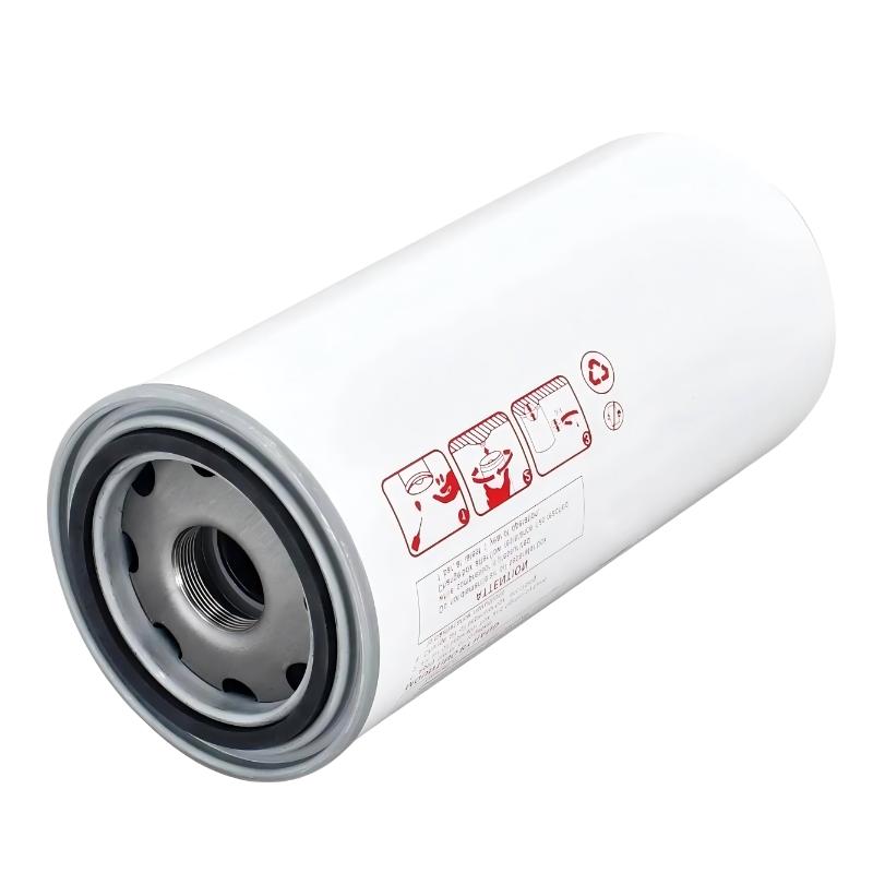

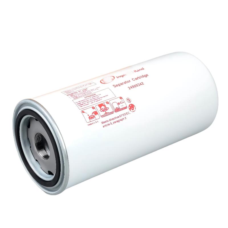
- Ingersoll Rand
- 47588445001 24900342
- Air Oil Separator
- USA
- 302 × 45 × 136 mm
- 0.91 kg
- Xiamen, China
- New & In Stock
- T/T, PayPal, Western Union
- 1 Year
- 1-3 Working Days
- DHL, UPS, TNT, FedEx and EMS.
- 24-Hour Service
- COO
- 3
Our advantage

Global Logistics
We have a 10-year logistics and express cooperation agreement, so our products can be shipped to any place in the world.

Brand new and original
Our products are imported in bulk from the place of origin. Because of the cooperative relationship, our products are all original and 100% new.

24-hour service
We provide 7*24 hours service to our customers. We will be there whenever you need us.

Price advantage
All our products are priced very favorably because we have our own warehouse and supply.
| Company Information | |||
| [email protected] | |||
| Mobile | +8615980777398 | ||
| +8615980777398 | |||
| 15980777398 |
Product Overview
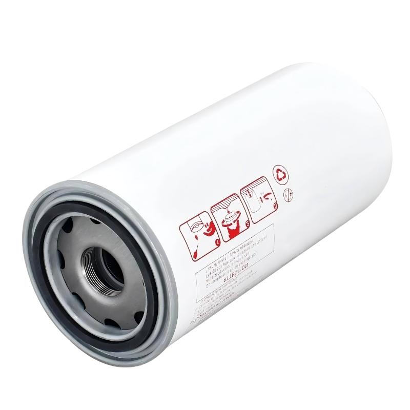
The Ingersoll Rand 47588445001 24900342 Air Oil Separator is a replacement component for compatible oil-injected rotary screw air compressors. It separates entrained lubricant from compressed air before the air enters the downstream delivery system, helping maintain air quality while allowing recovered oil to return to the compressor’s lubrication circuit.
During compression, the screw air end produces an air-oil mixture. Lubricating oil helps seal the compression chambers, reduces friction between moving components, and carries away heat generated during operation. Before the compressed air leaves the compressor, the separation stage removes most of the suspended oil droplets so that the lubricant can be recovered rather than continuously lost through the discharge outlet.
The 24900342 part number is associated with Ingersoll Rand air/oil separator applications, including certain rotary screw compressor configurations. The associated 47588445001 reference should be checked against the equipment’s parts identification and installed separator arrangement to establish the correct replacement. Part-number matching alone may not distinguish between separator configurations that use different mounting or flange arrangements.
Separator condition affects both compressed air quality and compressor operating performance. As oil and contaminants accumulate within the filtration media, airflow resistance can increase. A restricted separator may raise the pressure differential across the separation stage, while damaged media or a defective sealing interface can allow excessive oil to pass into the discharge air.
Consider a production facility operating a compressor that supplies pneumatic tools, automated machinery, and air treatment equipment. If the separator becomes inefficient, oil carryover can contaminate downstream piping and increase the maintenance requirements of filters, dryers, and other equipment. Investigating the separator alongside the oil return circuit and compressor operating conditions helps identify the source of the problem.
Replacing the separator requires more than selecting a part with a matching reference. The mounting arrangement, sealing surfaces, oil recovery connections, and separator housing must all be compatible. A correctly fitted element supports the intended separation process, whereas an incorrect configuration or damaged seal can compromise performance even when the filtration media is new.
Technical Specifications
| Parameter | Specification |
|---|---|
| Manufacturer | Ingersoll Rand |
| Model Reference | 47588445001 |
| Part Number | 24900342 |
| Product Type | Air Oil Separator |
| Product Category | Rotary Screw Air Compressor Spare Part |
| Primary Function | Separates entrained oil from compressed air |
| Separation Technology | Coalescing filtration |
| Application | Compatible Ingersoll Rand oil-injected rotary screw compressors |
| Installation Location | Compressor air/oil separation assembly |
| Operating Medium | Compressed air and entrained lubricating oil |
| Oil Recovery Function | Supports collection and return of separated lubricant |
| Maintenance Purpose | Replacement of a worn, contaminated, or restricted separator |
| Mounting Configuration | Must match the installed separator assembly |
| Dimensions | 302 × 45 × 136 mm |
| Weight | 0.91 kg |
Product Features
- Oil mist separation: Removes entrained lubricant droplets from the compressed air stream through coalescing filtration.
- Lubricant recovery: Supports the collection and return of separated oil to the compressor’s lubrication circuit.
- Compressed air quality: Helps limit oil carryover into downstream piping and pneumatic equipment.
- Pressure differential management: Supports normal airflow when the separator remains within its specified service limits.
- Compressor system compatibility: Requires matching the part reference and separator configuration to the installed assembly.
- Maintenance replacement: Allows a serviceable separator element to be replaced without automatically replacing the complete compressor vessel.
- Sealing interface: Requires correct seating and sealing to prevent untreated air from bypassing the filtration media.
- Oil circulation support: Works with the oil return arrangement to retain lubricant within the compressor system.
- Condition-based servicing: Can be assessed through differential pressure, oil carryover, operating hours, and inspection findings.
- Part identification: Uses reference 24900342 for maintenance planning and replacement identification.
Working Principle
The 24900342 air/oil separator uses coalescing filtration to remove suspended oil droplets from the compressed air produced by an oil-injected screw compressor. The air-oil mixture enters the separation assembly, where the filter media captures oil droplets and allows the air to continue through the intended discharge path.
Screw Air End → Oil Separator Vessel → 24900342 Air Oil Separator → Minimum Pressure Valve → Aftercooler → Compressed Air Network
As the mixture passes through the filter media, fine oil droplets collect and combine into larger droplets. The separated lubricant drains toward the collection area of the separator assembly and is returned through the compressor’s oil recovery circuit. The remaining air continues toward the minimum pressure valve and downstream cooling equipment.
The efficiency of this process depends on the filter media, airflow, operating pressure, lubricant condition, and integrity of the separator assembly. A properly functioning element removes oil while maintaining the pressure drop expected under the specified operating conditions.
Over time, accumulated contamination can restrict airflow through the media. The resulting pressure differential may increase the energy required to maintain the required discharge pressure. The actual effect depends on the degree of restriction, compressor loading, and control strategy.
Excessive oil carryover can indicate damaged media, a defective seal, an incorrect separator installation, or a problem with the oil return circuit. Incorrect oil level, unsuitable lubricant, and abnormal operating conditions can also contribute to the same symptom. Replacing the element without checking these related conditions may leave the original fault unresolved.
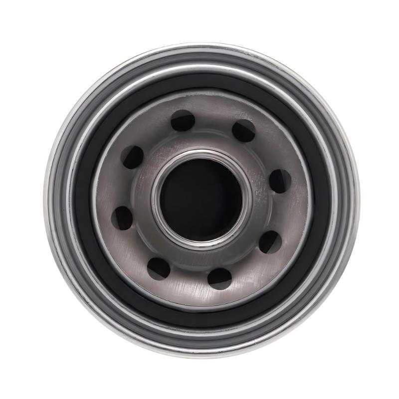
The separator must be installed in the configuration intended for the compressor. In particular, the 24900342 reference may be associated with different mounting arrangements, including flanged and non-flanged versions. The existing assembly should be inspected before selecting the replacement, and the sealing and connection arrangements must match the intended installation.
After replacement, the compressor should be operated according to its approved commissioning procedure. Technicians should check for leakage, abnormal differential pressure, excessive oil carryover, and correct oil return behavior before considering the maintenance complete.
Role in an Ingersoll Rand Compressed Air System
The air/oil separator occupies the separation stage between the screw air end and the downstream compressed air circuit. Its function is to recover lubricant from the air-oil mixture while allowing compressed air to proceed toward delivery and treatment equipment.
Ambient Air → Inlet Valve → Screw Air End → Oil Separator Assembly → Minimum Pressure Valve → Aftercooler → Air Receiver / Distribution Network
| System Component | Function |
|---|---|
| Ingersoll Rand 24900342 | Separates entrained oil from compressed air |
| Separator Housing | Contains the separation element and supports the operating pressure |
| Rotary Screw Air End | Compresses incoming air and produces an air-oil mixture |
| Compressor Lubricating Oil | Lubricates internal components and carries away heat |
| Oil Return Circuit | Returns recovered lubricant to the compressor |
| Minimum Pressure Valve | Regulates discharge flow and supports the required internal pressure |
| Aftercooler | Reduces compressed air temperature before downstream distribution |
| Air Receiver | Stores compressed air and accommodates changes in demand |
| Downstream Air Filters | Provide additional particulate or coalescing filtration where required |
| Differential Pressure Monitoring | Helps identify increasing resistance across the separator |
| Compressor Controller | Coordinates operating modes and monitors available operating signals |
| Plant Air Distribution Network | Delivers compressed air to connected machinery and pneumatic equipment |
Industrial Applications
| Application | Typical Use |
|---|---|
| General Manufacturing | Maintaining oil separation in central compressed air installations |
| Automotive Production | Supporting compressor operation in pneumatic manufacturing systems |
| Metalworking Facilities | Limiting oil carryover into air tools and production equipment |
| Packaging Machinery | Maintaining compressed air quality for automated production lines |
| Plastics Processing | Supporting oil-injected compressors used in manufacturing operations |
| Industrial Assembly | Maintaining separator performance during planned compressor servicing |
| Textile Manufacturing | Supporting compressed air supply to pneumatic machinery |
| Industrial Utility Rooms | Replacing restricted or deteriorated separator elements |
| Warehouse Operations | Maintaining compressors used for maintenance and material handling |
| Continuous-Operation Plants | Monitoring separator condition to reduce unplanned maintenance |
Installation and Maintenance
- Verify the part reference: Confirm 47588445001 and 24900342 against the compressor identification, parts documentation, and installed separator configuration.
- Check the mounting arrangement: Determine whether the existing assembly requires a flanged or non-flanged separator configuration before removing the old element.
- Review operating symptoms: Record differential pressure, oil carryover, lubricant consumption, and any relevant compressor alarms before maintenance.
- Isolate the compressor: Stop the equipment, disconnect the applicable electrical supply, and follow the site’s lockout/tagout procedure.
- Depressurize the system: Confirm that the separator vessel and connected piping are fully depressurized according to the approved service procedure.
- Document the original installation: Record the separator orientation, sealing arrangement, oil return connections, and associated hardware before disassembly.
- Inspect the housing: Check the separator mounting surface, internal supports, connections, and sealing interfaces for damage or contamination.
- Examine the removed element: Look for restricted media, damaged seals, deformation, or other signs that may explain the original operating symptoms.
- Install the replacement: Fit the separator according to the applicable service instructions, ensuring correct seating and matching the required mounting configuration.
- Check the oil return circuit: Inspect the return line and associated passages for blockage, leakage, or incorrect routing that could interfere with lubricant recovery.
- Test after reassembly: Restore the compressor to service under controlled conditions and check for leakage, abnormal differential pressure, and excessive oil carryover.
- Record maintenance results: Document the installed part number, operating hours, initial symptoms, pressure readings, and post-maintenance observations.
Related Components
| Component | Function |
|---|---|
| Ingersoll Rand 24900342 | Air/oil separator reference for compatible compressor assemblies |
| Separator Housing | Supports the separator and maintains the intended pressure boundary |
| Minimum Pressure Valve | Regulates discharge flow from the separator assembly |
| Oil Return Line | Carries separated lubricant back to the compressor |
| Compressor Oil Filter | Removes contaminants from circulating lubricant |
| Compressor Lubricating Oil | Provides lubrication, sealing, and heat removal |
| Aftercooler Assembly | Reduces compressed air temperature after the separation stage |
| Air Receiver | Stores compressed air and helps accommodate demand changes |
| Differential Pressure Monitoring Device | Helps identify increasing separator restriction |
| Downstream Air Filter | Provides additional air treatment where required |
| Compressor Controller | Monitors available operating conditions and coordinates compressor operation |
Recommended Related Models
| Model / Product Family | Product Type | Typical Application |
|---|---|---|
| Ingersoll Rand 24900342 | Air Oil Separator | Replacement separator for compatible compressor configurations |
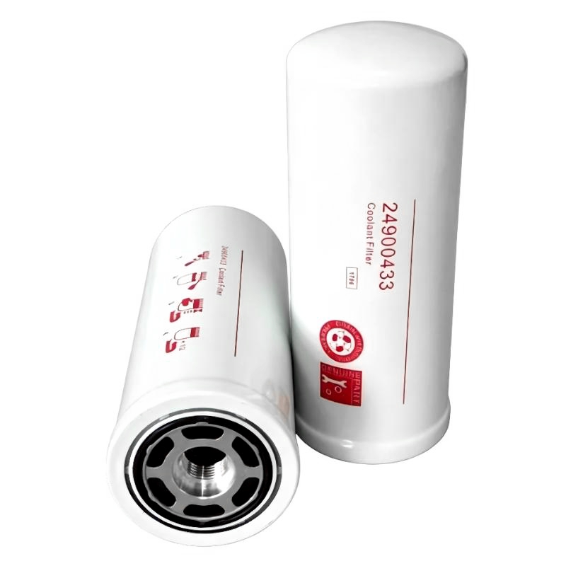
| Ingersoll Rand 24900433 | Oil Filter Element | Filtering circulating lubricant in specified compressor applications |
| Ingersoll Rand 48958235 | Air/Oil Separator Element | Related separator reference used in certain Ingersoll Rand compressor configurations |
| Ingersoll Rand 48958193 | Air Filter Element | Intake air filtration in specified compressor applications |
| Ingersoll Rand 47588445001 | Compressor Spare Part Reference | Identifying the associated maintenance and replacement application |
| Ingersoll Rand Minimum Pressure Valve | Compressor Pressure-Control Component | Regulating discharge flow from the separator vessel |
| Ingersoll Rand Oil Return Components | Compressor Lubrication Components | Returning separated oil to the lubrication circuit |
| Ingersoll Rand Aftercooler Assembly | Compressed Air Cooling Component | Reducing discharge air temperature |
Key Advantages
- Separates entrained oil from compressed air in compatible rotary screw compressors.
- Supports lubricant recovery through the compressor’s oil return circuit.
- Helps control oil carryover into downstream air treatment equipment.
- Supports expected airflow when maintained within the applicable pressure-drop limits.
- Allows replacement of the separator element without automatically replacing the complete vessel.
- Provides a defined part reference for maintenance planning and replacement identification.
Technical FAQs
Why must the mounting configuration be checked when replacing the 24900342 separator?
The 24900342 reference appears in listings for both flanged and non-flanged separator designs. The replacement must match the existing assembly’s mounting and sealing arrangement; a matching part number alone may not establish the correct physical configuration.
What operating symptoms can indicate that the separator requires replacement?
Increasing differential pressure, excessive oil carryover, or abnormal lubricant consumption can indicate a deteriorated or restricted separator. These symptoms can also result from a blocked oil return circuit, incorrect oil level, or other operating problems, so the complete separation system should be inspected.
How does a restricted separator affect compressor performance?
As the filter media becomes restricted, the pressure drop across the separator may increase. The compressor may then require additional energy to maintain the desired discharge pressure, depending on its operating conditions and control strategy.
Why should the oil return circuit be inspected after separator replacement?
The oil return circuit removes collected lubricant from the separation assembly and returns it to the compressor. A blocked or incorrectly connected return line can interfere with oil recovery and contribute to excessive carryover or abnormal oil consumption even when the separator element is new.