

ProductPRODUCT
Featured products
Contact Us
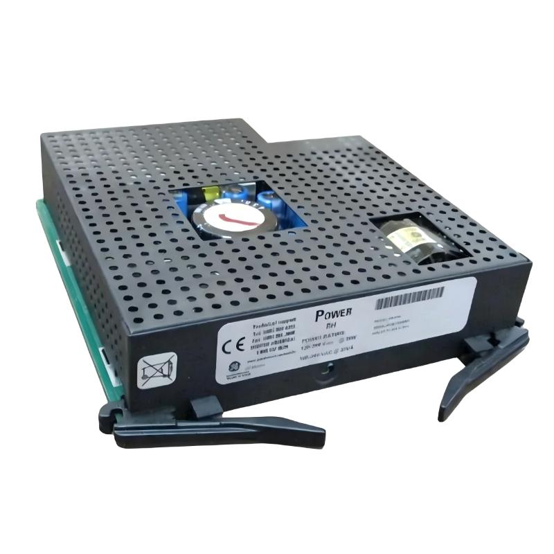
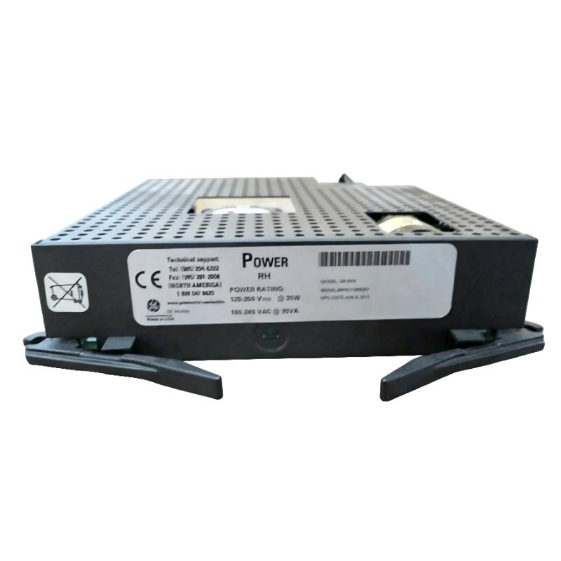
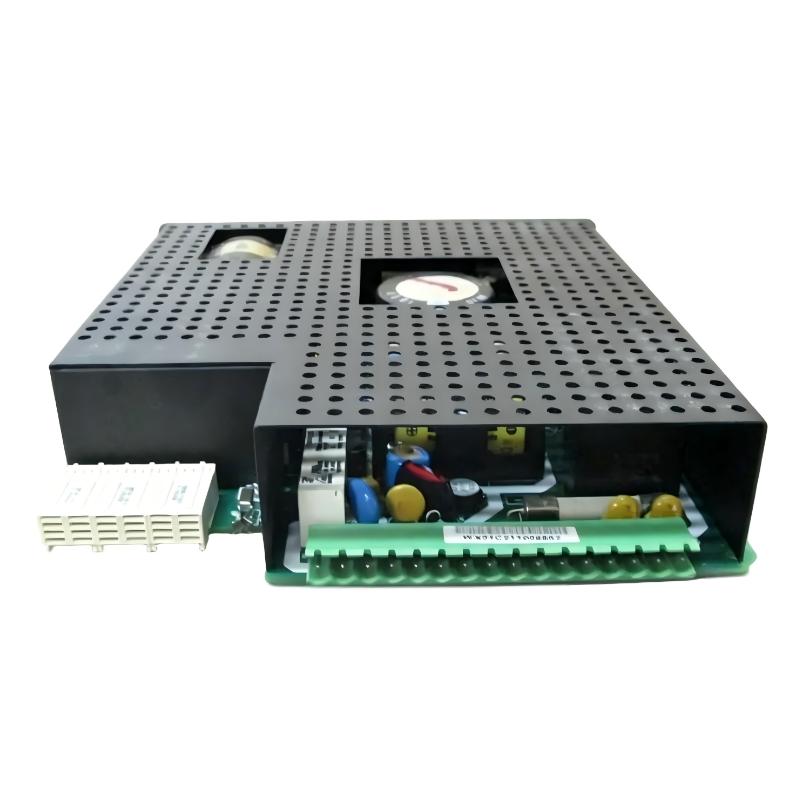
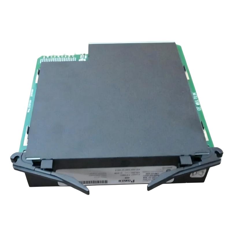
- GE
- UR RHV
- Power Supply Module
- USA
- 120 × 30 × 100 mm
- 0.98 kg
- Xiamen, China
- New & In Stock
- T/T, PayPal, Western Union
- 1 Year
- 1-3 Working Days
- DHL, UPS, TNT, FedEx and EMS.
- 24-Hour Service
- COO
- 3
Our advantage

Global Logistics
We have a 10-year logistics and express cooperation agreement, so our products can be shipped to any place in the world.

Brand new and original
Our products are imported in bulk from the place of origin. Because of the cooperative relationship, our products are all original and 100% new.

24-hour service
We provide 7*24 hours service to our customers. We will be there whenever you need us.

Price advantage
All our products are priced very favorably because we have our own warehouse and supply.
| Company Information | |||
| [email protected] | |||
| Mobile | +8615980777398 | ||
| +8615980777398 | |||
| 15980777398 |
Product Overview
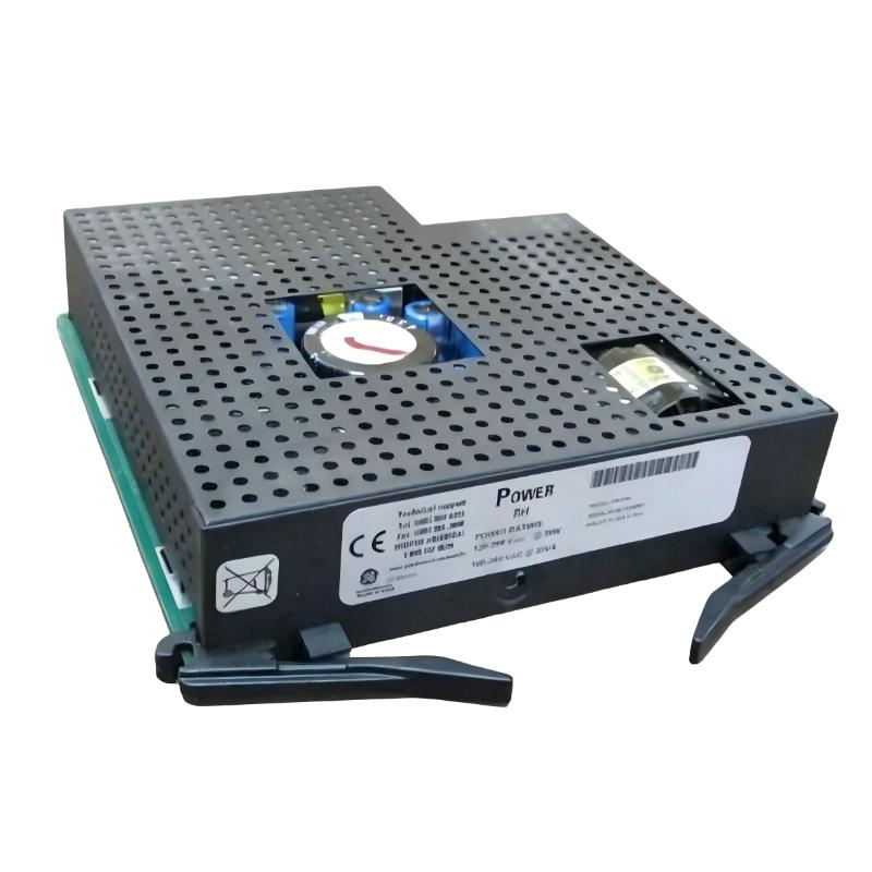
The GE UR RHV Multilin UR Series Power Supply Module is a power supply component used in GE Multilin Universal Relay (UR) protection and control systems. It supplies the operating power required by the relay’s internal electronic circuits, allowing the protection device to perform its configured monitoring, protection, control, and communication functions.
Within a UR relay installation, the power supply module supports the operation of the main processor, measurement circuits, communication interfaces, and other installed functional modules. Its role is particularly important in transformer protection, generator protection, feeder protection, and other applications where relay availability is essential to the overall protection scheme.
When maintaining an existing UR relay, identifying the correct power supply module is a key step in replacement planning. Compatibility must be assessed against the specific relay model, installed hardware configuration, and required supply input. Selecting the appropriate module helps preserve the intended operation of the protection system without introducing unnecessary changes to the existing relay setup.
Technical Specifications
| Parameter | Specification |
|---|---|
| Brand | GE |
| Product Model | UR RHV |
| Product Series | Multilin UR Series |
| Product Type | Power Supply Module |
| Product Family | Universal Relay |
| Primary Function | Relay power supply |
| Application | Protection and control systems |
| System Role | Supplies operating power to relay electronics |
| Installation Type | Relay-mounted module |
| Supported Equipment | Compatible GE Multilin UR relays |
| Supply Input | Verify against the specific module nameplate |
| Output Characteristics | Dependent on the installed power supply version |
| Replacement Consideration | Confirm hardware and power supply compatibility |
| Dimensions | 120 × 30 × 100 mm |
| Weight | 0.98 kg |
Product Features
- Power supply for UR relay electronics: Supplies operating power to the electronic circuits within a compatible Multilin UR relay, supporting normal protection and control functions.
- Integration with the UR platform: Forms part of the modular UR relay hardware architecture, allowing the power supply to operate alongside the relay’s processing, measurement, input/output, and communication functions.
- Support for protection system availability: A correctly functioning power supply is necessary for the relay to remain operational and execute its configured protection logic.
- Suitable for maintenance and replacement work: The module can be considered during troubleshooting when a UR relay exhibits power-related faults, fails to start, or shows abnormal operating indications.
- Hardware configuration awareness: UR relays can be supplied in different hardware configurations. The replacement module should match the requirements of the specific relay rather than being selected solely by the general series name.
- Compatibility-focused replacement: Checking the existing module identification, input requirements, connector arrangement, and relay configuration helps reduce the risk of installing an incompatible component.
- Support for established protection schemes: Retaining the correct power supply hardware helps maintenance teams preserve the existing relay installation and avoid unnecessary changes to protection settings or panel wiring.
- Application across industrial power systems: The UR platform is used in protection applications involving transformers, generators, feeders, motors, and other power system equipment, depending on the relay model and installed functions.
Working Principle
The GE UR RHV Multilin UR Series Power Supply Module receives electrical power from its designated input and converts it into the operating power required by the compatible relay hardware. The internal power conversion circuitry supplies the necessary electrical power to the relay’s electronic subsystems.
During normal operation, the module supports the processor and associated circuits that acquire measurements, evaluate protection conditions, execute configured logic, and manage communication with other devices. The relay uses these functions to determine whether measured electrical conditions require an alarm, a control action, or a protective trip.
The general operating sequence is as follows:
- Power input: The module receives power from the designated source connected to the relay.
- Power conversion: Internal circuitry converts the input into the supply levels required by the relay electronics.
- Internal power distribution: The converted power supports the processor and other installed functional circuits.
- Relay operation: The relay processes measurements, evaluates configured protection settings, and performs its assigned monitoring and control tasks.
- Protection response: When the configured logic detects a qualifying condition, the relay can initiate the appropriate output or trip command, provided the relevant hardware and protection functions are installed and operational.
The power supply module does not independently determine whether a transformer, feeder, or generator is experiencing a fault. Its purpose is to maintain the electrical power required for the relay’s protection and control functions to operate.
Role in a Multilin UR Protection and Control Architecture
The UR RHV power supply module occupies the power distribution position within a compatible Universal Relay assembly. It supports the electronic hardware responsible for measurement processing, protection algorithms, programmable logic, and communication.
| System Component | Function | Relationship to the Power Supply Module |
|---|---|---|
| UR Relay Main Processor | Executes protection algorithms and control logic | Requires operating power to process measurements and commands |
| Analog Measurement Circuits | Acquire electrical quantities from connected instrument transformers or sensors | Depend on the relay’s power system for electronic operation |
| Digital Input Modules | Monitor external status signals and contact conditions | Require powered relay electronics to process input states |
| Digital Output Modules | Operate configured control, alarm, or trip outputs | Depend on the functioning relay and associated output circuitry |
| Communication Interfaces | Exchange status, measurement, and control information | Require operating power for communication hardware |
| Front Panel and Display | Provides local access to relay status, measurements, and settings | Depends on the relay electronics and display hardware being powered |
| External DC or AC Supply | Provides the electrical source for the relay power supply | Must match the input requirements of the installed module |
| Circuit Breaker or Trip Circuit | Executes a protective switching action when commanded | Receives commands from the relay’s configured output circuits |
A power supply problem can affect several relay functions at once. For this reason, troubleshooting should distinguish between a loss of incoming supply, a fault within the power supply module, a connection issue, and a separate problem in the relay hardware.
Industrial Applications
| Application | Typical Use of the Multilin UR Relay Platform | Power Supply Module’s Contribution |
|---|---|---|
| Transformer Protection | Monitoring transformer operating conditions and executing configured differential, overcurrent, or other protection functions | Supplies operating power for the relay hardware performing the assigned protection tasks |
| Generator Protection | Supporting generator electrical protection and associated control functions on compatible UR models | Maintains power for measurement processing and protection logic |
| Feeder Protection | Monitoring distribution feeders and responding to configured fault conditions | Supports continuous operation of the feeder protection relay |
| Motor Protection | Supporting motor protection functions on compatible UR relay models | Powers the relay electronics used for monitoring and protective responses |
| Bus Protection | Supporting bus protection schemes where compatible UR equipment is installed | Supplies power for the relay hardware participating in the protection scheme |
| Industrial Substations | Providing protection and control within switchgear and substation panels | Supports relay availability within the installed electrical protection system |
| Power Generation Facilities | Operating as part of generator and auxiliary system protection arrangements | Enables the assigned relay to perform its configured functions |
| Electrical Maintenance and Retrofit Projects | Replacing faulty hardware in established protection installations | Helps restore relay operation when the power supply module is identified as the cause of a fault |
The exact protection functions available in an installation depend on the specific UR relay model, firmware, hardware configuration, and application settings. The power supply module itself does not determine which protection functions are enabled.
Installation and Maintenance
- Verify the module identification: Confirm the complete model designation and the installed power supply version before beginning replacement work.
- Check the relay compatibility: Verify that the module is suitable for the specific Multilin UR relay model and hardware configuration.
- Confirm the input supply: Compare the available supply source with the input requirements shown on the installed module’s identification label and applicable equipment documentation.
- Isolate the equipment: Follow the site’s electrical safety procedures and isolate the relevant supply before removing or installing the module. Do not assume that the relay is de-energized merely because its display is off.
- Inspect the mounting arrangement: Check the module’s seating, retaining hardware, and mechanical interface for damage or signs of improper installation.
- Examine electrical connections: Inspect accessible connectors and terminals for looseness, corrosion, contamination, discoloration, or evidence of overheating.
- Check the surrounding environment: Look for excessive dust, moisture, conductive contamination, or abnormal temperature conditions that could affect the relay assembly.
- Install the replacement correctly: Align the module with its intended mounting position and connector arrangement. Do not force the module into place if the mechanical fit is incorrect.
- Restore power according to procedure: Reconnect the supply only after the installation has been checked and all applicable electrical safety requirements have been met.
- Verify startup indications: Observe the relay’s available status indicators and front-panel messages, where fitted, to determine whether the equipment has returned to its expected operating state.
- Review relay operation: Confirm that the relay completes its startup sequence and that the relevant measurements, protection functions, alarms, and communication interfaces operate as expected.
- Record the maintenance activity: Document the removed and installed module identification, observed symptoms, test results, and any corrective action taken for future troubleshooting and maintenance planning.
If the relay remains inoperative after replacement, check the incoming supply, connection integrity, module compatibility, and relay hardware condition before concluding that the replacement module is defective. Any protection testing or return-to-service decision should follow the site’s approved commissioning and maintenance procedures.
Related Components
| Component | Function | Relationship to the UR RHV Power Supply Module |
|---|---|---|
| GE Multilin UR Relay Main Unit | Hosts the relay’s processing and protection functions | The principal assembly supported by the power supply module |
| UR Relay CPU or Processor Module | Executes protection logic and system processing | Requires operating power supplied through the relay hardware architecture |
| UR Analog Input or Measurement Hardware | Acquires electrical measurements for protection functions | Works with the powered relay electronics to process measured values |
| UR Digital Input Module | Monitors external contacts and status signals | Supports status acquisition within the powered relay |
| UR Digital Output Module | Provides configured alarm, control, and trip outputs | Operates as part of the relay’s powered output architecture |
| UR Communication Module or Interface | Provides communication with supervisory and control systems | Requires operating power for communication functions |
| External Power Supply Circuit | Feeds the relay’s designated power input | Provides the source required by the power supply module |
| Relay Chassis and Mounting Hardware | Holds the relay’s installed hardware | Maintains the mechanical installation and module alignment |
Recommended Related Models
| Model or Product Family | Product Type | Relevance |
|---|---|---|
| GE Multilin UR T60 | Transformer Protection Relay | Relevant to transformer protection installations using the UR platform |
| GE Multilin UR G60 | Generator Protection System | Relevant to generator protection applications |
| GE Multilin UR F60 | Feeder Protection System | Relevant to feeder protection and distribution applications |
| GE Multilin UR L90 | Line Differential Protection System | Relevant to line protection applications |
| GE Multilin UR M60 | Motor Protection System | Relevant to motor protection installations |
| GE Multilin UR B30 | Bus Differential Protection System | Relevant to bus protection applications |
| GE Multilin UR C60 | Breaker Management Relay | Relevant to breaker control and management applications |
The models listed above belong to the broader Multilin UR product family. They are related by platform or application, but their power supply requirements and hardware compatibility must be checked individually. The UR RHV designation alone is not sufficient to establish interchangeability across all UR relay models.
Key Advantages
- Supports the operating power requirements of compatible GE Multilin UR relay hardware.
- Fits into maintenance and replacement workflows for established UR protection installations.
- Helps restore relay operation when a verified power supply fault is responsible for equipment downtime.
- Supports the relay electronics used for protection processing, monitoring, and communication.
- Allows maintenance teams to focus on the identified hardware fault without automatically replacing the entire relay assembly.
Technical FAQs
1. What is the function of the GE UR RHV Multilin UR Series Power Supply Module?
It supplies operating power to the electronic circuits in a compatible GE Multilin UR relay. These circuits perform the relay’s configured measurement, protection, control, and communication functions.
2. Can the UR RHV power supply module be used with every Multilin UR relay?
Not necessarily. Compatibility depends on the specific relay model, hardware revision, power supply version, input requirements, and mechanical interface. The complete module identification should be checked before replacement.
3. What should be checked if a UR relay does not start?
Check the incoming power source, supply wiring, connectors, module installation, and compatibility with the relay. If the incoming supply is correct and the relay still fails to start, further troubleshooting may be required to distinguish a power supply fault from a problem elsewhere in the relay assembly.
4. Does replacing the power supply module change the relay’s protection settings?
Replacing a power supply module does not normally serve as a method of changing protection settings. However, the relay’s settings, status, and protection functions should be verified after maintenance in accordance with the site’s approved procedures before the equipment is returned to service.