

ProductPRODUCT
Featured products
Contact Us
- GE
- T60G01HCHF8FH6PM8HP6PUXXWXX
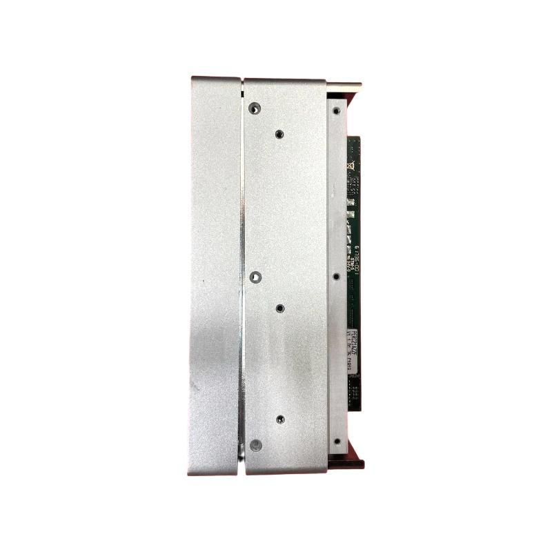
- Transformer Management Relay Front Panel
- USA
- 200 × 260 × 35 mm
- 0.7 kg
- Xiamen, China
- New & In Stock
- T/T, PayPal, Western Union
- 1 Year
- 1-3 Working Days
- DHL, UPS, TNT, FedEx and EMS.
- 24-Hour Service
- COO
- 4
Our advantage

Global Logistics
We have a 10-year logistics and express cooperation agreement, so our products can be shipped to any place in the world.

Brand new and original
Our products are imported in bulk from the place of origin. Because of the cooperative relationship, our products are all original and 100% new.

24-hour service
We provide 7*24 hours service to our customers. We will be there whenever you need us.

Price advantage
All our products are priced very favorably because we have our own warehouse and supply.
| Company Information | |||
| [email protected] | |||
| Mobile | +8615980777398 | ||
| +8615980777398 | |||
| 15980777398 |
Product Overview
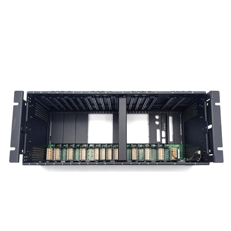
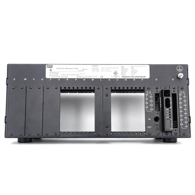
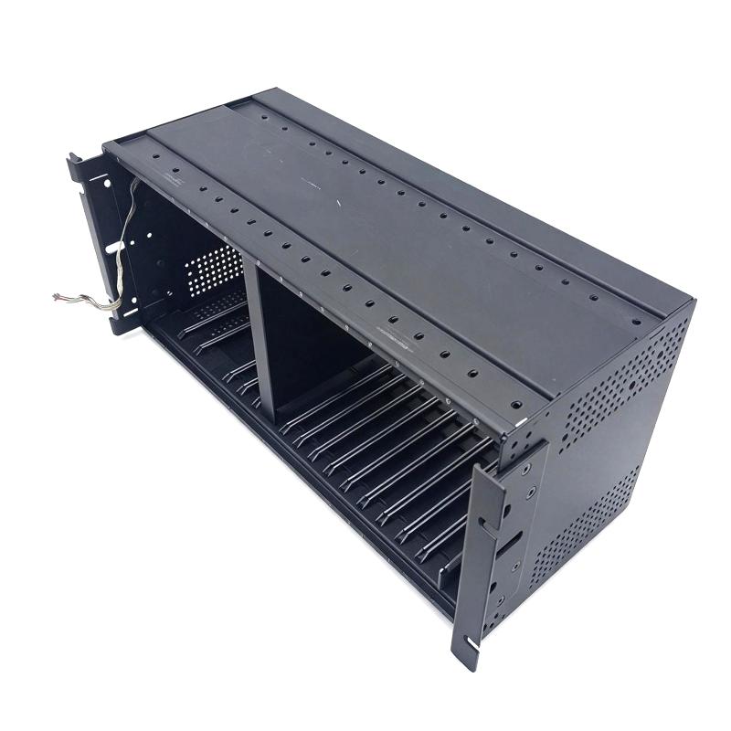
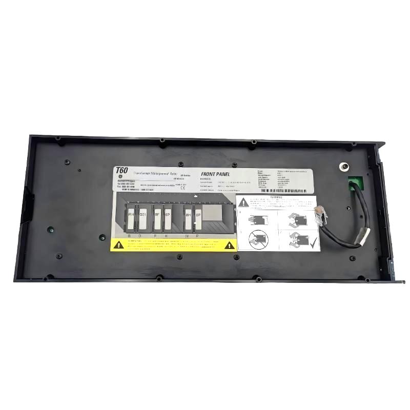
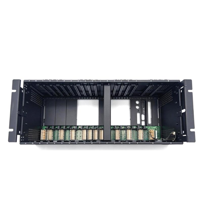
The GE T60G01HCHF8FH6PM8HP6PUXXWXX Multilin T60 Transformer Management Relay Front Panel is associated with the GE Multilin T60 transformer protection and management relay platform. The T60 is used in transformer protection applications where electrical measurements, protection functions, and relay status information are handled by the installed protection system. The front panel serves as the operator-facing interface for accessing relay information and interacting with the configured device.
In a substation or power distribution installation, the relay front panel gives protection engineers and maintenance personnel a local point for viewing operating conditions, checking relay indications, and navigating available settings or diagnostic information. During commissioning and routine maintenance, local access can help technicians verify relay status without relying exclusively on remote monitoring software.
The complete ordering code identifies a specific T60 configuration. When selecting a replacement front panel, the full part number and the installed relay version should be checked against equipment records. A front panel that appears similar may not have the same interface arrangement or compatibility with the existing relay assembly.
The front panel is distinct from the relay’s internal protection hardware. Protection functions such as transformer differential protection, current and voltage supervision, and associated logic depend on the configured relay and its installed functions. The front panel provides an access point to the device rather than independently performing transformer protection calculations.
For maintenance teams supporting existing GE Multilin installations, matching the correct panel configuration helps preserve the intended local operating interface and supports consistent access to relay information during inspection, testing, and service work.
Technical Specifications
| Parameter | Specification |
|---|---|
| Brand | GE |
| Product Model | T60G01HCHF8FH6PM8HP6PUXXWXX |
| Product Series | Multilin T60 |
| Product Type | Transformer Management Relay Front Panel |
| Product Category | Protective relay operator interface component |
| Intended Equipment | GE Multilin T60 Transformer Management Relay |
| Primary Function | Local relay status viewing and operator access, subject to the installed panel configuration |
| Application | Transformer protection and management systems |
| Installation Location | Front of a compatible relay assembly or equipment panel |
| Interface Functions | Must be confirmed against the exact panel configuration |
| Relay Protection Functions | Determined by the installed T60 relay configuration |
| Replacement Requirement | Match the complete ordering code and compatible relay version |
| Dimensions | 200 × 260 × 35 mm |
| Weight | 0.7 kg |
Product Features
- Multilin T60 platform association: The front panel is identified with the GE Multilin T60 transformer management relay family, which is used in transformer protection applications.
- Local operator access: The panel serves as the local interface for viewing relay information and accessing available operator functions supported by the installed configuration.
- Relay status visibility: Local indications and display functions, where provided by the specific panel version, help personnel check device status during routine inspections.
- Access to configured information: The operator interface may allow access to relay measurements, event information, settings, and diagnostic menus according to the installed relay and panel configuration.
- Configuration-specific identification: The complete ordering code helps distinguish the required panel variant from other T60 components and configurations.
- Support for commissioning activities: A functioning local interface can assist technicians with relay checks, configuration verification, and maintenance procedures.
- Integration with transformer protection equipment: The panel belongs to the operator-interface side of a protection relay installation and works with the compatible T60 relay assembly.
- Maintenance replacement capability: A correctly matched replacement can restore local access when the original panel is damaged or its interface functions become unavailable.
- Equipment-level serviceability: The front panel can be inspected separately from internal relay electronics when troubleshooting a local interface problem.
- Support for operational inspection: Local access helps maintenance personnel review available relay information while working at the protection cabinet.
Working Principle
The GE Multilin T60 Transformer Management Relay Front Panel functions as the local operator interface for a compatible T60 relay assembly. It allows the user to interact with the relay through the interface elements supported by the installed version. The relay’s internal electronics remain responsible for processing electrical measurements and executing configured protection logic.
A general interaction sequence is:
Operator input → Front panel interface → Compatible T60 relay functions → Displayed status or response
When a technician requests information or navigates the available interface, the relay processes the request and returns the relevant information for presentation. Depending on the specific configuration, this may include operating status, measurements, settings, alarms, or event information.
The panel does not independently calculate transformer differential quantities or make protection decisions. Those functions are handled by the relay’s internal processing hardware and configured protection algorithms. The front panel provides access to the information and operator functions made available by the relay.
During normal operation, the panel supports local inspection and interaction. If the display, keys, indicators, or other interface elements fail to respond as expected, technicians should check the panel connection, relay status, and applicable equipment diagnostics before determining whether the fault is limited to the front panel or involves the relay itself.
Role in a Transformer Protection Architecture
Within a transformer protection system, the GE Multilin T60 relay processes electrical inputs and executes the configured protection functions. The front panel forms part of the local human-machine interface, allowing personnel to inspect relay information and access available operator functions at the installed device.
The panel is separate from the current transformers, voltage transformers, trip circuits, and other primary protection components. Its role is to support local interaction with the relay rather than directly measure transformer currents or interrupt fault current.
| Architecture Layer | Component or Function | Relationship to the T60 Front Panel |
|---|---|---|
| Power system layer | Power transformer and associated electrical equipment | Represents the equipment protected by the T60 relay |
| Measurement layer | Current transformers and voltage transformers | Supply electrical measurements to the protection system through the applicable input circuits |
| Protection processing layer | GE Multilin T60 relay hardware and configured protection functions | Processes measurements and executes the configured protection logic |
| Operator interface layer | T60 front panel | Provides local access to available relay status, measurements, settings, and diagnostic information |
| Trip and control layer | Circuit breaker trip circuits and associated control wiring | Carries protection trip or control signals generated by the configured protection system |
| Supervisory layer | Substation monitoring or control system | May receive relay data through supported communication interfaces independently of local panel operation |
| Maintenance layer | Test equipment, wiring records, and service procedures | Supports inspection, configuration verification, and replacement of the panel or associated relay components |
Industrial Applications
| Application | Role of the T60 Front Panel |
|---|---|
| Power transformer protection | Provides local operator access to a T60 relay used in transformer protection applications |
| Electrical substations | Allows maintenance personnel to inspect relay information at the protection cabinet |
| Power generation facilities | Supports local checks of transformer protection equipment associated with plant electrical systems |
| Transmission and distribution networks | Provides an operator interface for compatible T60 relay installations protecting power transformers |
| Industrial power distribution | Supports local inspection of transformer protection relays serving plant electrical infrastructure |
| Transformer commissioning | Helps technicians access available relay information while checking the installed protection system |
| Relay configuration and verification | Provides access to supported local menus or settings, depending on the installed configuration and access permissions |
| Preventive maintenance | Allows personnel to review available indications and relay information during scheduled inspections |
| Protection relay troubleshooting | Helps distinguish local interface problems from faults involving relay processing or associated equipment |
| Substation equipment refurbishment | Can be considered as a replacement component when the installed panel has been identified as defective |
| Legacy protection system maintenance | Supports continued service of existing T60 installations when a compatible panel is required |
| Spare-parts management | Provides a full ordering-code reference for identifying and tracking the required panel variant |
Installation and Maintenance
- Verify the complete ordering code: Compare T60G01HCHF8FH6PM8HP6PUXXWXX with the installed component and equipment records before beginning replacement work.
- Confirm relay compatibility: Check that the replacement panel is intended for the installed GE Multilin T60 relay version. Do not rely on a similar appearance or a shared product family alone.
- Follow the approved isolation procedure: Apply the site’s electrical safety and maintenance procedures before working on the relay assembly. Determine whether the equipment must be isolated or placed in a maintenance state.
- Record the existing configuration: Document the relay identification, panel arrangement, and any relevant settings or maintenance information before removing the existing component.
- Inspect the panel before installation: Check for cracks, damaged interface elements, bent connectors, contamination, or other visible defects that could affect installation or operation.
- Check the connection arrangement: Confirm the applicable panel connection and mounting details against the relay documentation. Avoid forcing connectors or altering the assembly to accommodate an unverified replacement.
- Handle electronic components carefully: Follow appropriate electrostatic discharge precautions when handling exposed electronic connections or components. Use suitable protective equipment and antistatic handling practices.
- Install the panel correctly: Align the panel with the intended mounting arrangement and secure it according to the equipment’s service procedure. Avoid excessive pressure that could damage the panel or its connectors.
- Inspect the surrounding relay assembly: Check accessible connectors, mounting points, and nearby wiring for looseness or visible damage before restoring the equipment to service.
- Restore the equipment according to procedure: Complete the required checks before returning the relay to its normal operating state. Follow site requirements for authorization, isolation removal, and restoration of protection functions.
- Verify local interface operation: Confirm that the panel responds as expected and that available status information can be accessed. Where required, perform the applicable relay functional checks using approved procedures.
- Document the maintenance work: Record the replacement part number, observed fault, work performed, and post-installation results. Update equipment records and spare-parts information as necessary.
Troubleshooting considerations: If the local interface remains unavailable after replacement, check the panel connection, relay power and status, and the relevant diagnostic information. A display or operator-interface fault does not necessarily indicate that the relay’s protection functions have also failed. Follow the approved protection-system maintenance procedure before making further changes.
Related Components
| Component | Function | Relationship to the T60 Front Panel |
|---|---|---|
| GE Multilin T60 relay assembly | Processes electrical measurements and executes configured transformer protection functions | The primary equipment with which the front panel is associated |
| T60 relay control electronics | Handle internal processing and device operation | Support the functions accessed through the local interface |
| Current transformer inputs | Supply current measurements to the protection relay | Provide input signals for configured protection functions rather than connecting directly to the panel as a protection element |
| Voltage measurement circuits | Supply voltage information where supported by the relay configuration | Contribute electrical data used by applicable relay functions |
| Circuit breaker trip circuit | Carries trip commands to the relevant switching equipment | Operates through the protection and control arrangement, not through the front panel alone |
| Relay communication interface | Supports data exchange with supervisory or engineering systems | Provides a separate means of accessing supported relay information |
| Relay power supply | Supplies operating power to the relay assembly | Supports operation of the relay and its associated interface |
| Protection test equipment | Supports approved testing of relay functions and inputs | Helps verify the protection system during commissioning or maintenance |
| Relay configuration records | Document settings and device configuration | Assist technicians in preserving the intended configuration during maintenance |
| Panel mounting hardware | Secures the panel to the relay or enclosure | Maintains the intended mechanical installation |
Recommended Related Models
| Model | Product Description | Relationship |
|---|---|---|
| GE Multilin T60 | Transformer Management Relay | Main relay platform associated with the specified front panel |
| GE Multilin T60 front panel variants | T60 relay front panel configurations | Related components that require ordering-code and relay-version verification before substitution |
| GE Multilin T60 relay assemblies | Transformer protection and management relay assemblies | Related equipment for which the front panel serves as a local operator interface |
| GE Multilin T60 replacement interface components | Relay interface replacement components | May be relevant to panel maintenance, subject to exact part-number compatibility |
| GE Multilin transformer protection relays | Transformer protection relay products | Related product category, but different relay models may use different hardware and interfaces |
Key Advantages
- Local relay access: Supports inspection and interaction with a compatible T60 relay at the equipment location.
- Specific ordering-code identification: Helps maintenance teams identify the intended panel variant for replacement.
- Support for protection-system maintenance: Provides a local interface for routine checks and approved service activities.
- Separation of interface and protection functions: Allows technicians to investigate panel-related issues without automatically assuming an internal protection-processing failure.
- Equipment integration: Fits into the local operator-interface arrangement of a compatible T60 installation.
- Maintenance traceability: Recording the complete part number helps organize replacement planning and service records.
Technical FAQs
1. What is the GE T60G01HCHF8FH6PM8HP6PUXXWXX Multilin T60 Transformer Management Relay Front Panel used for?
It is identified as a front panel associated with the GE Multilin T60 transformer management relay platform. Its role is to provide local operator access to supported relay information and interface functions. The exact features depend on the installed panel and relay configuration.
2. Does the T60 front panel perform transformer protection calculations?
No. Transformer protection calculations and configured protection logic are handled by the relay’s internal processing hardware. The front panel serves as the operator interface for accessing available information and functions.
3. Can this front panel be used with every GE Multilin T60 relay?
Compatibility should not be assumed from the T60 family name alone. Verify the complete ordering code, relay version, interface arrangement, and applicable equipment documentation before selecting a replacement.
4. What should be checked if the T60 front panel does not respond?
Check the panel connection, relay power and status, and any available diagnostic information according to the approved maintenance procedure. If the issue persists, determine whether the fault is limited to the interface or involves the wider relay assembly before replacing additional components.