

ProductPRODUCT
Featured products



Contact Us
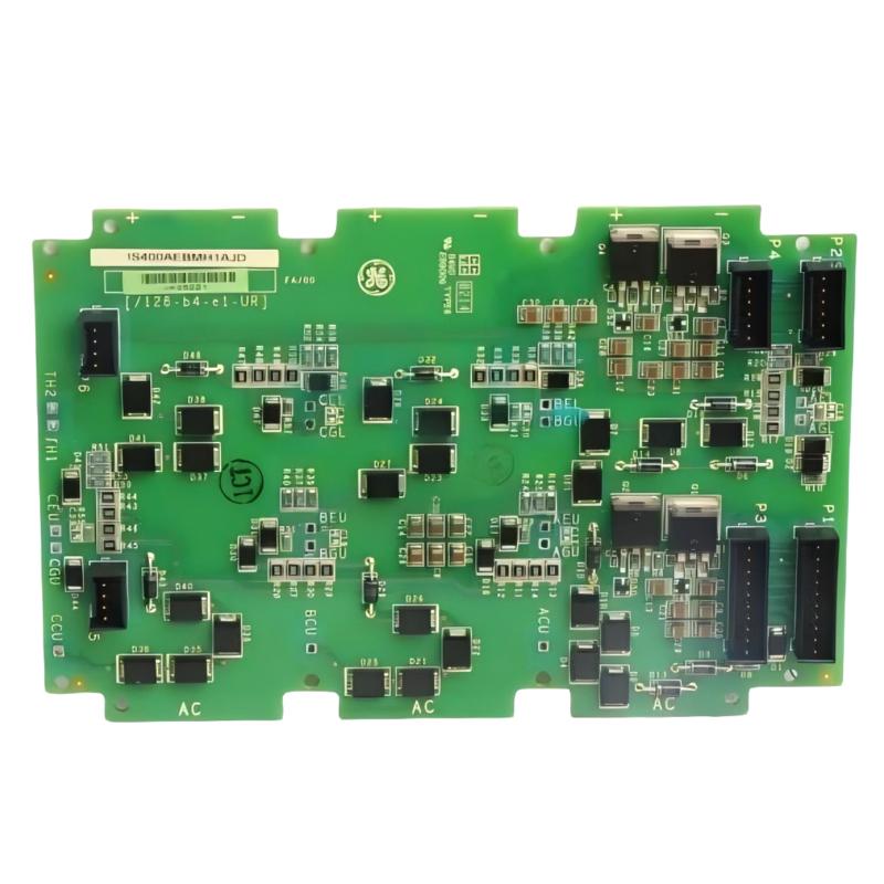
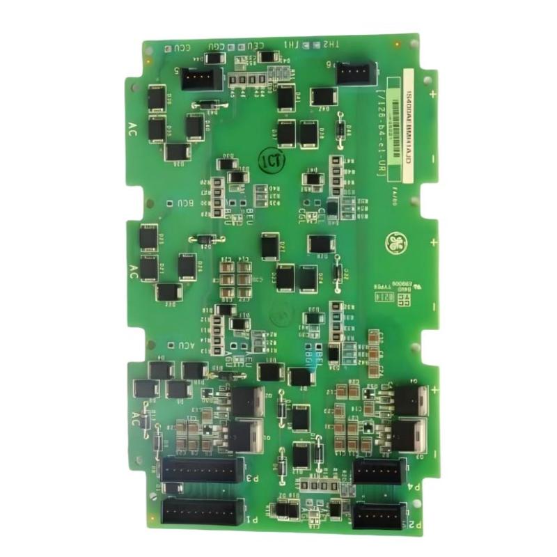

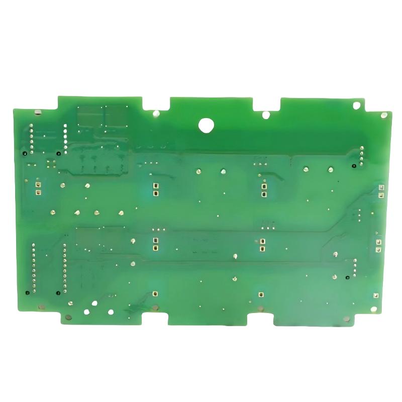
- GE
- IS400AEBMH1AJD
- Heatsink Module
- USA
- 140 × 32 × 120 mm
- 0.113 kg
- Xiamen, China
- New & In Stock
- T/T, PayPal, Western Union
- 1 Year
- 1-3 Working Days
- DHL, UPS, TNT, FedEx and EMS.
- 24-Hour Service
- COO
- 14
Our advantage

Global Logistics
We have a 10-year logistics and express cooperation agreement, so our products can be shipped to any place in the world.

Brand new and original
Our products are imported in bulk from the place of origin. Because of the cooperative relationship, our products are all original and 100% new.

24-hour service
We provide 7*24 hours service to our customers. We will be there whenever you need us.

Price advantage
All our products are priced very favorably because we have our own warehouse and supply.
| Company Information | |||
| [email protected] | |||
| Mobile | +8615980777398 | ||
| +8615980777398 | |||
| 15980777398 |
Product Overview
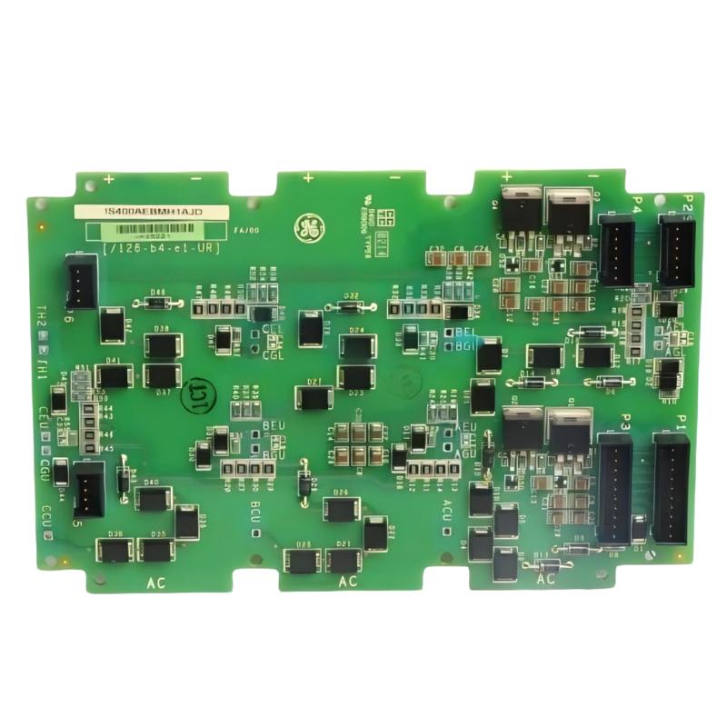
The GE IS400AEBMH1AJD Heatsink Module is an industrial hardware component designed for thermal management within compatible electronic control equipment. Heat dissipation is an important consideration in industrial automation because electronic components generate heat during operation, and excessive temperatures can affect component reliability, operating stability, and equipment service life.
A heatsink provides a thermal path that helps transfer heat away from a component or assembly into the surrounding environment. Depending on the equipment design, this process may involve conductive contact between the heat source and the heatsink, followed by heat dissipation through the heatsink surface. The effectiveness of the arrangement depends on the thermal characteristics of the components, mounting conditions, airflow, and operating environment.
The GE IS400AEBMH1AJD is identified as a heatsink module associated with the GE IS400 hardware designation. Its precise installation location, supported electronic assembly, thermal rating, and mechanical interface should be confirmed using the applicable equipment documentation. These details are important when selecting a replacement because heatsinks with similar physical dimensions may differ in mounting geometry and thermal performance.
With supplied dimensions of 140 × 32 × 120 mm and a weight of approximately 0.113 kg, the IS400AEBMH1AJD offers a compact physical profile for industrial equipment planning and spare-parts management. Correct identification helps maintenance personnel select the intended component without introducing mechanical or thermal compatibility problems.
For industrial maintenance teams, the heatsink should be treated as part of the complete thermal design rather than as an isolated accessory. Proper installation, secure contact with the intended heat source, and suitable environmental conditions all contribute to reliable operation.
Technical Specifications
| Parameter | Specification |
|---|---|
| Manufacturer | General Electric (GE) |
| Model | IS400AEBMH1AJD |
| Product Type | Heatsink Module |
| Product Family | GE IS400 Series designation |
| Primary Function | Heat dissipation and thermal management |
| Application | Compatible industrial electronic equipment |
| Thermal Interface | Verify according to the equipment design |
| Mounting Arrangement | Confirm from the applicable hardware documentation |
| Cooling Method | Passive heat dissipation or system-dependent arrangement; verify before installation |
| Thermal Rating | Confirm from the applicable technical specification |
| Compatible Electronic Assembly | Verify using the original equipment documentation |
| Dimensions | 140 × 32 × 120 mm |
| Weight | 0.113 kg |
| Installation | Compatible GE industrial control equipment |
| Maintenance | Inspection of mounting, contact surfaces, cleanliness, and surrounding airflow |
The supplied model number, dimensions, and weight form the basis of this specification table. Detailed thermal ratings, mounting requirements, and compatible assemblies should be confirmed before replacement or commissioning.
What Is a Heatsink Module?
A heatsink is a thermal-management component that transfers heat away from an electronic device or assembly. Electronic components generate heat as electrical energy is consumed during normal operation. If this heat is not removed adequately, component temperatures can rise beyond their intended operating range.
A heatsink typically uses a thermally conductive structure to receive heat from a component and spread it across a larger surface area. Heat can then be transferred to the surrounding air through natural convection or, where the system design provides it, assisted airflow.
A simplified thermal path can be represented as:
Electronic Component → Thermal Contact Surface → Heatsink Structure → Surrounding Air
The actual arrangement depends on the equipment’s mechanical and thermal design. The IS400AEBMH1AJD should be installed only in the position and configuration intended for the specific host assembly.
Function and Working Principle
Heat Transfer From Electronic Components
Electronic components generate heat through electrical losses during operation. The amount of heat depends on the component’s electrical characteristics, operating load, and design.
A heatsink provides a path for this heat to move away from the source. Good thermal contact between the component and the heatsink is important because gaps, contamination, or improper mounting can increase thermal resistance.
Heat Distribution Across the Heatsink
After heat enters the heatsink, it spreads through the thermally conductive material. A larger effective surface area can improve heat transfer to the surrounding air, although actual performance depends on geometry, material properties, and airflow.
The exact material and internal structure of the IS400AEBMH1AJD should not be assumed without the applicable product specification.
Heat Dissipation to the Environment
Heat leaves the heatsink through convection and thermal radiation. In a naturally cooled installation, the surrounding air movement is primarily determined by the cabinet layout and environmental conditions. In systems with forced ventilation, airflow may improve heat removal when designed appropriately.
Obstructed ventilation, high ambient temperatures, and excessive dust can reduce cooling effectiveness.
Maintaining Operating Temperature
The purpose of thermal management is to help keep the associated electronic components within their specified operating-temperature limits. Maintaining appropriate temperature conditions can reduce thermal stress and support reliable equipment operation.
A heatsink alone cannot compensate for every cooling problem. Cabinet ventilation, component loading, thermal interfaces, and other cooling elements must work together as intended.
Role in Industrial Control Systems
Industrial control equipment often contains electronic assemblies that operate continuously or under varying electrical loads. Thermal management is therefore an important part of equipment design and maintenance.
The GE IS400AEBMH1AJD may serve as a dedicated thermal component within a compatible industrial electronic assembly. Its exact role depends on the host equipment and the component with which it is designed to interface.
Typical functions associated with industrial heatsinks include:
- Providing a thermal path away from electronic components.
- Increasing the surface area available for heat dissipation.
- Supporting stable operating temperatures.
- Helping reduce temperature-related stress on electronic assemblies.
- Contributing to the overall thermal design of control equipment.
- Supporting equipment reliability when correctly installed and maintained.
The module should not be assumed to include a fan, temperature sensor, active cooling circuit, or independent temperature-control function unless the applicable documentation confirms these features.
Industrial Applications
Heatsinks are widely used in industrial electronic equipment where components generate heat during normal operation. The suitability of the IS400AEBMH1AJD for a particular application depends on its verified mechanical and thermal compatibility.
Industrial Control Cabinets
Control cabinets house electronic assemblies, power components, interface hardware, and other equipment that may generate heat. Properly designed heatsinks help manage local temperatures within these installations.
Automation Electronics
Industrial automation systems rely on electronic hardware to process signals, execute control functions, and connect different system elements. Depending on the design, thermal-management components may be required to maintain acceptable operating conditions.
Power and Interface Assemblies
Electronic power and interface circuits can generate heat due to electrical losses. A correctly matched heatsink helps transfer heat away from the intended component and into the surrounding cooling environment.
Continuous-Duty Equipment
Some industrial systems operate for extended periods with limited downtime. Effective thermal management helps support reliable operation by reducing the risk of excessive component temperature.
Equipment Maintenance and Repair
Heatsinks may require inspection or replacement if they become damaged, corroded, improperly mounted, or unable to maintain the intended thermal contact. Correct identification of the replacement component is important because mechanical fit and thermal performance must both be suitable.
These examples describe general heatsink applications and do not establish a specific end use for the IS400AEBMH1AJD without confirmation from the host-system documentation.
Installation and System Integration
Correct installation is essential for effective heat transfer. A heatsink that is mechanically loose, incorrectly positioned, or poorly coupled to its intended heat source may provide inadequate cooling even if the component itself is undamaged.
1. Verify the Component Identity
Confirm the complete model number IS400AEBMH1AJD and compare it with the existing component, equipment parts list, and applicable maintenance documentation.
Check the mounting features, contact surface, orientation, and surrounding clearances before installation. Similar-looking heatsinks should not be assumed to be interchangeable.
2. Follow Electrical Safety Procedures
Before accessing the host assembly, follow the facility’s approved isolation and lockout/tagout procedures. Ensure that the equipment is in a safe condition and that relevant electrical hazards have been addressed.
Electronic components and heatsinks may remain hot after equipment shutdown. Allow sufficient cooling time before handling the assembly.
3. Inspect the Mounting Surface
Examine the mounting points and thermal contact surface for damage, contamination, corrosion, or deformation. A damaged contact surface may reduce heat transfer or prevent correct mechanical installation.
Clean the surfaces only using methods and materials approved for the equipment.
4. Verify Thermal Interface Requirements
Some heatsink arrangements require a specified thermal interface material, pad, or other contact method. Others may use a different manufacturer-defined arrangement.
Follow the original equipment instructions. Do not add thermal paste, pads, washers, or other materials unless they are specified for the installation, because an incorrect interface can affect thermal performance or mechanical clearance.
5. Install the Heatsink Correctly
Position the heatsink according to the specified orientation and mounting arrangement. Use the approved fasteners and tightening procedure, ensuring that the assembly is secure without damaging the mounting points.
Avoid excessive force, which can deform the heatsink or damage the associated electronic component.
6. Check Airflow and Clearance
Confirm that the heatsink is not obstructed by cables, neighboring components, cabinet panels, or accumulated dust. Maintain the ventilation clearances specified for the host equipment.
Where forced airflow is part of the system design, verify that the intended airflow path remains unobstructed.
7. Perform Post-Installation Checks
After installation, inspect the assembly for secure mounting and correct alignment. Follow the approved equipment startup procedure and monitor relevant temperature or diagnostic indicators where available.
If the equipment shows abnormal temperature behavior, investigate the complete cooling arrangement rather than assuming that the heatsink alone is responsible.
Troubleshooting the GE IS400AEBMH1AJD
Thermal problems should be investigated as part of the complete electronic assembly. Excessive temperature may result from an incorrect heatsink, poor thermal contact, restricted airflow, high ambient temperature, abnormal electrical loading, or a problem with the associated cooling system.
Excessive Component Temperature
If an electronic component operates above its expected temperature, inspect:
- Heatsink mounting and alignment.
- Contact between the heatsink and its intended heat source.
- Condition of the thermal interface, where applicable.
- Cabinet ventilation and surrounding airflow.
- Accumulated dust or other contamination.
- Ambient temperature and equipment loading.
- Relevant system diagnostics.
Compare measured conditions with the equipment’s specified operating limits. Do not continue operating equipment beyond its permitted thermal limits while the cause remains unresolved.
Heatsink Feels Unusually Hot
A hot heatsink does not automatically indicate a failure. A heatsink is designed to receive and dissipate heat, so its temperature depends on the component load, ambient conditions, and thermal design.
Assess the actual component temperature and compare it with the specified limits. Investigate further if there are associated alarms, abnormal performance, or signs of overheating.
Cooling Performance Has Decreased
Reduced cooling effectiveness may be caused by restricted airflow, dust accumulation, poor contact, a damaged heatsink, or changes to the cabinet layout.
Inspect the cooling path and verify that all components are installed as designed. Correct any obstruction or mounting issue before returning the equipment to normal operation.
Loose or Damaged Mounting
Loose fasteners, damaged threads, bent mounting surfaces, or incorrect hardware can prevent the heatsink from making proper thermal contact.
Replace damaged mounting components as required by the approved maintenance procedure. Do not compensate for an incorrect fit by forcing the assembly into position.
Repeated Thermal Alarms
Repeated temperature alarms may indicate insufficient cooling capacity, excessive equipment loading, a defective cooling fan where fitted, inaccurate temperature sensing, or an installation problem.
Review alarm records and operating conditions. Confirm whether the reported temperature reflects a real thermal problem or a sensor or diagnostic issue before replacing parts.
Thermal Problems After Replacement
If the associated equipment begins operating at higher temperatures after a heatsink replacement, verify the model number, mounting orientation, contact surface, thermal interface, and required clearances.
A component that fits physically may still have an unsuitable thermal design. Confirm the replacement’s suitability before continued operation.
Maintenance Recommendations
Preventive maintenance helps preserve thermal performance and reduce the risk of temperature-related failures.
Inspect the Heatsink Surface
Check for physical damage, deformation, corrosion, contamination, or other conditions that may affect heat transfer. Replace the component if it no longer meets the installation requirements.
Keep Cooling Paths Clean
Remove dust and debris according to the facility’s maintenance procedure. Ensure that cleaning methods do not damage nearby electronics or force contaminants into sensitive components.
Verify Mounting Integrity
Inspect mounting points and fasteners for looseness or damage. Follow the specified tightening requirements rather than applying an assumed torque value.
Check Thermal Interface Condition
Where the equipment uses a replaceable thermal interface material, inspect and renew it according to the manufacturer’s procedure. Reuse or replacement requirements depend on the specified material and installation method.
Monitor Operating Conditions
Review available temperature readings and system alarms during scheduled maintenance. Comparing measurements under similar operating conditions can help identify gradual deterioration in cooling performance.
Maintain the Cabinet Environment
Keep ambient temperature, ventilation, dust levels, and moisture within the specified limits for the equipment. A clean and properly ventilated cabinet helps the heatsink dissipate heat effectively.
Record Maintenance Activities
Document the component model, inspection results, replacement history, and any associated thermal alarms. Accurate records can help identify recurring cooling issues and simplify future maintenance.
Compatible System Components
The IS400AEBMH1AJD may form part of an electronic assembly that includes several functional hardware categories. Exact compatible components must be verified against the host equipment documentation.
| Component Category | Typical Function |
|---|---|
| Electronic Control Assembly | Houses the circuitry requiring thermal management |
| Heat-Generating Component | Produces heat during normal operation |
| Heatsink Module | Transfers heat away from the intended component |
| Thermal Interface Material | Supports thermal contact where specified |
| Mounting Hardware | Secures the heatsink in the intended position |
| Cabinet Ventilation System | Supports heat removal from the enclosure |
| Cooling Fan, Where Fitted | Provides forced airflow according to the system design |
| Temperature Monitoring Hardware, Where Fitted | Measures or reports temperature conditions |
| Control-System Diagnostics | Reports relevant equipment status or alarms where supported |
This table describes general thermal-management components, not a confirmed list of specific parts compatible with the IS400AEBMH1AJD. The actual configuration depends on the equipment in which the heatsink is installed.
Replacement and Procurement Considerations
When sourcing a replacement for the GE IS400AEBMH1AJD Heatsink Module, it is important to verify both the mechanical interface and the thermal requirements of the original installation.
Before ordering, confirm the following details:
- Complete model number: IS400AEBMH1AJD
- Revision or identification markings, where applicable.
- Original equipment and installation location.
- Mounting-hole arrangement and orientation.
- Contact-surface geometry.
- Thermal interface requirements.
- Required clearance and airflow conditions.
- Compatibility with the associated electronic assembly.
The supplied dimensions are 140 × 32 × 120 mm, and the listed weight is 0.113 kg. These values are useful for inventory control, equipment handling, and physical installation planning.
Do not select an alternative solely because it has similar dimensions. Different heatsinks can have different thermal resistance, contact geometry, mounting arrangements, and airflow requirements. Verify that any proposed replacement is approved for the intended assembly.
Key Advantages
Dedicated Thermal Management
A suitable heatsink provides a defined path for heat transfer away from the electronic component it is designed to support.
Compact Physical Profile
The supplied dimensions of 140 × 32 × 120 mm and weight of 0.113 kg support practical equipment planning and spare-parts management.
Support for Electronic Reliability
Proper heat dissipation helps keep associated components within their specified operating-temperature limits.
Integration With Industrial Equipment
When matched to the intended host assembly, the heatsink contributes to the overall thermal design of the industrial electronic system.
Maintainable Mechanical Design
Correct identification and inspection of the mounting arrangement help maintenance personnel evaluate the condition of the component and plan suitable replacement work.
Technical FAQs
What is the GE IS400AEBMH1AJD?
The GE IS400AEBMH1AJD is identified as a Heatsink Module intended for thermal management in compatible industrial electronic equipment.
What are the dimensions of the IS400AEBMH1AJD?
The supplied dimensions are 140 × 32 × 120 mm.
How much does the IS400AEBMH1AJD weigh?
The supplied weight is approximately 0.113 kg.
What is the purpose of a heatsink in industrial electronics?
A heatsink helps transfer heat away from an electronic component and dissipate it into the surrounding environment. This supports thermal control and helps reduce the risk of excessive component temperature.
Does the IS400AEBMH1AJD contain a cooling fan?
The supplied product information identifies it as a heatsink module but does not establish whether it includes a fan or another active cooling mechanism. Confirm the construction from the applicable hardware documentation.
What can cause poor heatsink performance?
Possible causes include poor thermal contact, incorrect mounting, contamination, restricted airflow, unsuitable replacement hardware, or excessive heat generation by the associated component.
Can another GE heatsink replace the IS400AEBMH1AJD?
Not automatically. The replacement must match the required mounting geometry, thermal performance, contact interface, and host-system requirements.
How should the heatsink be maintained?
Inspect the component for damage and contamination, maintain the intended airflow path, verify mounting integrity, and follow the specified procedure for any thermal interface material.
Conclusion
The GE IS400AEBMH1AJD Heatsink Module is an industrial thermal-management component intended to support heat dissipation within compatible electronic equipment. Effective thermal management is essential for maintaining appropriate component temperatures and supporting the long-term reliability of industrial control hardware.
With supplied dimensions of 140 × 32 × 120 mm and a weight of 0.113 kg, the component can be identified for spare-parts inventory, equipment planning, and replacement preparation. Its suitability depends on the correct mounting arrangement, thermal interface, airflow conditions, and compatibility with the intended electronic assembly.
Before replacing the IS400AEBMH1AJD, confirm the complete model designation and the relevant installation requirements. Careful identification, correct mounting, clean cooling paths, and regular inspection help maintain effective heat transfer and support reliable industrial equipment operation.