

ProductPRODUCT
Featured products



Contact Us
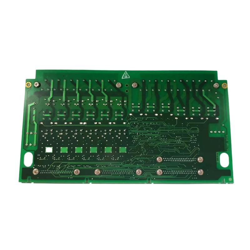
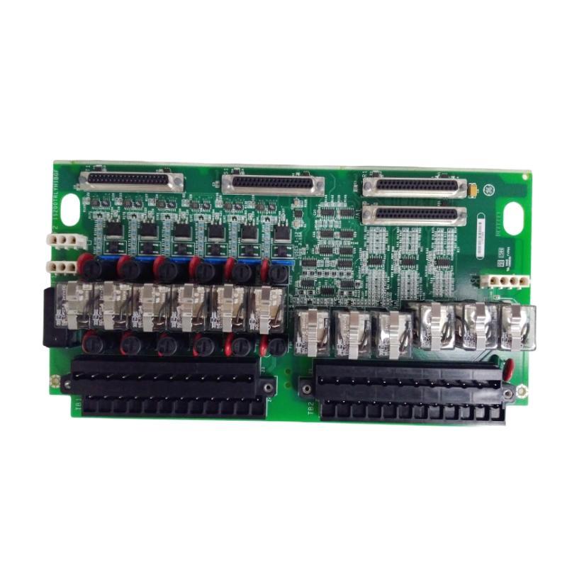
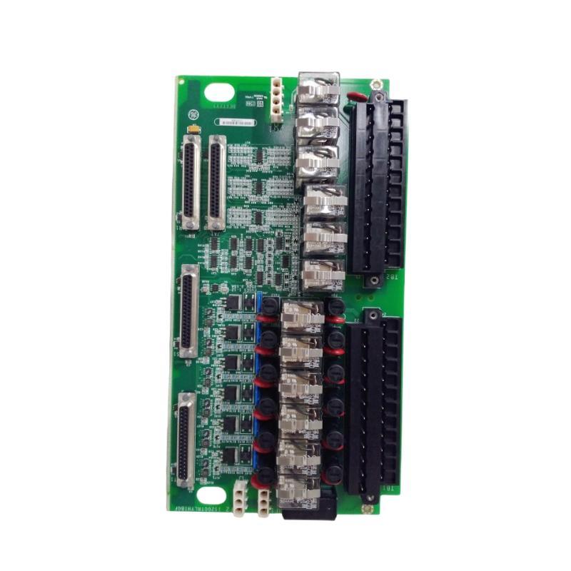
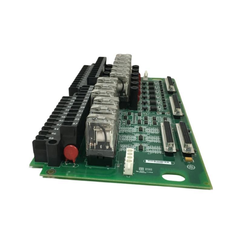
- GE
- IS230TRLYH1B
- Relay Output Terminal Block
- USA
- 45 × 280 × 210 mm
- 0.9 kg
- Xiamen, China
- New & In Stock
- T/T, PayPal, Western Union
- 1 Year
- 1-3 Working Days
- DHL, UPS, TNT, FedEx and EMS.
- 24-Hour Service
- COO
- 19
Our advantage

Global Logistics
We have a 10-year logistics and express cooperation agreement, so our products can be shipped to any place in the world.

Brand new and original
Our products are imported in bulk from the place of origin. Because of the cooperative relationship, our products are all original and 100% new.

24-hour service
We provide 7*24 hours service to our customers. We will be there whenever you need us.

Price advantage
All our products are priced very favorably because we have our own warehouse and supply.
| Company Information | |||
| [email protected] | |||
| Mobile | +8615980777398 | ||
| +8615980777398 | |||
| 15980777398 |
Product Overview
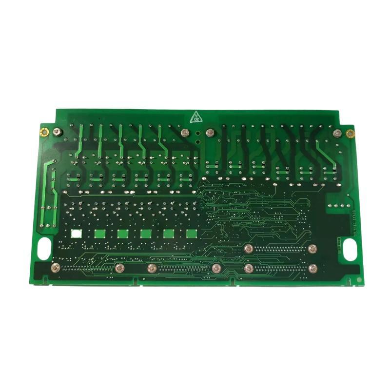
The GE IS230TRLYH1B Relay Output Terminal Block is an industrial control component designed for relay-related signal connections within compatible GE automation and control systems. Terminal blocks play an important role in industrial installations by providing organized electrical connection points between control electronics, field wiring, and external equipment. In relay output applications, these connections support the transfer of switching signals from a control system to associated electrical circuits.
The IS230TRLYH1B is intended for use in an appropriate industrial control configuration where reliable wiring, clear signal routing, and maintainable electrical connections are essential. Relay output interfaces are commonly used to control external devices such as auxiliary relays, contactor coils, alarm circuits, and other control loads, provided that the connected equipment meets the electrical ratings and interface requirements of the installed system.
With listed dimensions of 45 × 280 × 210 mm and a weight of approximately 0.9 kg, the GE IS230TRLYH1B is a practical component for industrial control cabinets and equipment assemblies. Its physical characteristics are relevant when planning panel layouts, arranging wiring routes, and preparing replacement components for maintenance work.
Correct identification is especially important when working with GE IS230-series hardware. Components that appear similar may have different electrical functions, connector arrangements, or system compatibility requirements. The complete model designation should therefore be checked before installation or replacement.
Technical Specifications
| Parameter | Specification |
|---|---|
| Manufacturer | General Electric (GE) |
| Model | IS230TRLYH1B |
| Product Type | Relay Output Terminal Block |
| Product Family | GE IS230 Series |
| Primary Function | Relay output connection and terminal interface |
| Application | Industrial control and automation |
| Interface Role | Electrical connection between compatible control hardware and associated circuits |
| Output Type | Relay-related output interface; detailed configuration requires verification |
| Number of Channels | Confirm from the applicable hardware documentation |
| Contact Configuration | Confirm from the installed hardware specification |
| Rated Voltage | Verify according to the applicable system documentation |
| Rated Current | Verify according to the applicable system documentation |
| Connection Method | Confirm terminal and connector arrangement before wiring |
| Dimensions | 45 × 280 × 210 mm |
| Weight | 0.9 kg |
| Installation | Compatible industrial control assembly |
| Maintenance | Inspection of terminals, connectors, wiring, and mounting condition |
The table identifies the product using the supplied model information and physical specifications. Electrical ratings, relay contact arrangements, terminal assignments, and the exact host-system configuration should be confirmed before the component is commissioned.
Function and Working Principle
The primary purpose of a relay output terminal interface is to support organized electrical connections for control signals that operate external devices. Within an industrial automation system, a controller evaluates process conditions and executes control logic. When an output command is issued, the associated output interface provides the switching action or connection required by the circuit design.
A simplified relay output control path can be represented as:
Controller Logic → Output Interface → Terminal Connections → External Control Circuit → Controlled Equipment
The precise arrangement depends on the installed GE control architecture and the electrical design of the application. The IS230TRLYH1B should not be assumed to contain a particular number of relays or a specific contact arrangement unless that information has been confirmed from the applicable documentation.
Electrical Signal Connection
Terminal interfaces provide defined connection points for wiring between control equipment and associated electrical circuits. Properly secured connections help reduce the likelihood of intermittent signals, unexpected switching behavior, and faults caused by loose conductors.
Relay Output Switching
Relay-based output circuits are commonly used where a control system must switch an external circuit in response to a programmed condition. Depending on the system design, these circuits may operate auxiliary devices, annunciation equipment, or other control loads.
The permissible load, switching voltage, and contact current must always remain within the ratings of the actual output device and connected circuit.
Control-System Integration
Within a larger automation installation, the terminal interface forms part of the electrical connection architecture. Its role is to support orderly signal routing and simplify troubleshooting by making connections accessible to qualified maintenance personnel.
Maintenance Accessibility
A well-organized terminal arrangement can make it easier to identify conductors, inspect connections, and isolate wiring faults. Accurate labeling and up-to-date wiring records are important for maintaining this benefit throughout the equipment’s service life.
Role in Industrial Control Systems
The GE IS230TRLYH1B Relay Output Terminal Block can be considered part of the connection layer within a compatible industrial control system. Control systems typically combine processors, I/O electronics, terminal assemblies, field wiring, and external devices to carry out automated operations.
The terminal interface contributes to the physical connection between the control equipment and the associated electrical circuits. Its performance depends on correct wiring, suitable electrical protection, secure mounting, and compatibility with the installed hardware.
Typical functions associated with relay output terminal arrangements include:
- Providing organized electrical connection points.
- Supporting relay-related control signal routing.
- Connecting control hardware to external circuits.
- Facilitating wiring identification and inspection.
- Supporting maintenance and fault isolation.
- Helping maintain a structured control cabinet layout.
The IS230TRLYH1B should be selected according to the actual function required in the host system. It should not be treated as a general-purpose controller, processor, or universal output module.
Industrial Applications
Relay output terminal interfaces are used in a range of industrial environments where automated control signals must be connected to external electrical circuits. The suitability of the IS230TRLYH1B for a particular application depends on the host equipment and the verified electrical specifications.
Industrial Machinery
Manufacturing equipment often uses relay-related output circuits to operate auxiliary control devices, indicate machine status, or coordinate different stages of a production sequence. A suitable terminal interface helps organize the wiring associated with these functions.
Power Generation and Electrical Control
Industrial power facilities use control systems to monitor equipment status and execute operational commands. Relay output circuits may be part of auxiliary control, alarm, and interlocking arrangements. Any use of the IS230TRLYH1B in such an installation must follow the equipment manufacturer’s design and safety requirements.
Process Automation
Chemical processing, water treatment, and other process industries rely on automated control systems to manage equipment and respond to operating conditions. Relay-related connections can support selected control and indication functions within these systems.
Equipment Status and Alarm Circuits
Control cabinets may contain alarm indicators, annunciators, and auxiliary devices that respond to output commands. Suitable relay output wiring helps connect these devices to the control architecture.
Industrial Equipment Maintenance
Replacement terminal assemblies are relevant when existing hardware has suffered connector damage, mechanical wear, contamination, or other problems that affect the reliability of electrical connections.
Installation and System Integration
Correct installation is essential for maintaining electrical reliability and preventing avoidable control-system faults. The IS230TRLYH1B should be installed only after its identity, intended function, and compatibility with the host equipment have been confirmed.
1. Verify the Model Number
Before installation, compare the replacement component with the original unit and the applicable equipment documentation. Check the complete IS230TRLYH1B designation, revision markings where present, connector locations, terminal arrangement, and mounting features.
Do not select a replacement based on physical appearance alone. Similar-looking components may serve different purposes.
2. Follow Electrical Safety Procedures
Before removing or installing the component, follow the facility’s approved isolation and lockout/tagout procedures. Confirm that the relevant circuits are in a safe state and that stored electrical energy has been addressed according to the equipment maintenance instructions.
Work should be performed by qualified personnel familiar with the installed control system.
3. Document Existing Wiring
Before disconnecting conductors, record terminal identifiers, wire labels, connector positions, and the routing of associated cables. Photographs and updated wiring records can help prevent wiring errors during reassembly.
Never assume that two visually similar terminals have identical electrical assignments.
4. Inspect Mounting and Connections
Examine the mounting surface, connectors, terminal contacts, and nearby wiring for damage, corrosion, discoloration, contamination, or signs of overheating. Confirm that the assembly can be secured properly and that connected cables will not be subjected to excessive mechanical stress.
5. Confirm Electrical Compatibility
Verify the required voltage, current, contact configuration, conductor requirements, and protective devices using the applicable technical documentation. The ratings of the complete output circuit must be suitable for the connected load.
Do not energize the assembly if the terminal assignments or electrical ratings remain uncertain.
6. Reconnect and Inspect Wiring
Reconnect the wiring according to the approved wiring diagram. Ensure that conductors are securely terminated and that no loose strands, exposed conductor sections, or misplaced wires can create short circuits.
Check cable routing and separation from power conductors where required by the installation design.
7. Perform Commissioning Checks
After installation, carry out the prescribed inspection and functional checks before returning the equipment to normal operation. Confirm that the associated control system recognizes the relevant hardware as expected and that output commands produce the intended response.
Functional testing should be performed under approved operating conditions and within the electrical limits of the system.
Troubleshooting the GE IS230TRLYH1B
When a relay output circuit fails to operate correctly, the problem may originate from the terminal interface, control electronics, field wiring, external relay, connected load, or control logic. Troubleshooting should therefore consider the entire circuit rather than assuming the terminal block itself is defective.
No Output Response
If an external device does not respond to an output command, inspect the following areas:
- Confirm that the control system is issuing the expected command.
- Review relevant controller diagnostics and alarm indications.
- Check the associated output electronics and wiring connections.
- Inspect terminal contacts and connectors for damage or poor contact.
- Verify the condition of external relays and connected loads.
- Confirm that circuit protection devices have not operated.
Testing should follow the system’s approved diagnostic procedure. Do not bridge terminals or bypass protective circuits as an improvised troubleshooting method.
Intermittent Output Operation
Intermittent operation may be associated with loose conductors, damaged cables, vibration, contamination, deteriorated contacts, or an unstable upstream control signal.
Inspect the wiring and connector condition while observing the system’s diagnostic information. Any physical inspection or adjustment must be performed under the appropriate electrical safety conditions.
Unexpected Switching
Unexpected output behavior may result from incorrect wiring, an unintended control command, a fault in associated output electronics, or a problem in the external circuit.
Review the control sequence, operating conditions, event records, and wiring diagram. Confirm that the output assignment matches the intended control function before replacing components.
Overheating or Discoloration
Signs of overheating around terminals or connectors may indicate a loose connection, excessive current, unsuitable conductor termination, or another electrical problem.
The affected circuit should be placed in a safe condition and inspected by qualified personnel. Identify and correct the underlying cause before returning the equipment to service.
Communication or System Diagnostic Alarms
A terminal block alone may not provide independent communication or diagnostic functions. If the host system reports a hardware or I/O alarm, investigate the associated control electronics, interface connections, configuration, and system diagnostics.
The exact meaning of an alarm should be determined from the documentation for the installed control platform.
Maintenance Recommendations
Preventive maintenance helps preserve connection integrity and supports long-term reliability in industrial control cabinets.
Periodic Visual Inspection
Inspect the terminal assembly and surrounding wiring for physical damage, contamination, corrosion, loose mounting, and signs of overheating. The inspection interval should reflect the operating environment and the facility’s maintenance program.
Terminal and Connector Condition
Check connections according to the manufacturer’s maintenance procedure. Where tightening is permitted, use the specified torque and approved tools. Do not apply an assumed torque value to an unidentified terminal.
Wiring and Label Verification
Ensure that conductors remain correctly identified and that labels are readable. Wiring documentation should be updated whenever modifications are made to the control system.
Environmental Protection
Maintain the cabinet environment within the limits specified for the installed equipment. Excessive dust, moisture, vibration, and heat can contribute to connection deterioration and premature hardware failure.
Functional Testing
Include relevant output circuits in scheduled maintenance tests where required by the equipment’s operating and safety procedures. Confirm that the control command, output interface, field wiring, and connected device operate as intended.
Replacement Planning
Maintain accurate inventory records for critical control components. Record the complete part number and any revision information needed to identify the correct replacement.
Compatible System Components
The IS230TRLYH1B may be used within a broader industrial control installation containing several categories of equipment. The exact compatible components must be established from the host system’s wiring diagrams, hardware manuals, and bill of materials.
| Component Category | Typical Function |
|---|---|
| Control Processor | Executes control logic and generates output commands |
| Output Control Electronics | Provides the required output signal or switching function |
| Relay Output Terminal Interface | Supports electrical connections for the associated output circuit |
| Field Wiring | Connects control equipment to external devices |
| Auxiliary Relays | Switch external circuits where specified by the design |
| Contactors and Control Devices | Operate compatible electrical loads |
| Circuit Protection Devices | Protect wiring and equipment against specified electrical faults |
| Operator Interface | Displays system status, alarms, and operating information |
| Cabinet Grounding System | Provides the required protective grounding arrangement |
This table describes functional categories, not a confirmed list of directly compatible part numbers. Exact interchangeability should be verified before purchasing or installing related hardware.
Recommended Replacement and Selection Considerations
Selecting the correct replacement for the GE IS230TRLYH1B requires more than matching its dimensions. Industrial control assemblies can share similar mechanical formats while differing significantly in electrical function and interface design.
Before procurement, verify the following details:
- Complete model number: IS230TRLYH1B
- Revision or hardware identification markings
- Product function and intended circuit role
- Terminal and connector arrangement
- Required electrical ratings
- Host-system compatibility
- Mounting and clearance requirements
- Condition of the existing wiring and associated hardware
If a supplier proposes an alternative model, request confirmation that the replacement is approved for the same application. Do not assume that another GE IS230-series component is interchangeable solely because it belongs to the same product family.
For maintenance inventories and installation planning, the supplied physical specifications are 45 × 280 × 210 mm and 0.9 kg. Confirm the measurement orientation and mounting envelope against the actual assembly before preparing cabinet space.
Key Advantages
Organized Electrical Connections
A suitable relay output terminal interface helps keep control wiring structured and easier to identify during installation and maintenance.
Support for Industrial Control Circuits
Relay-related terminal arrangements can form part of automated switching, alarm, and auxiliary control circuits when correctly matched to the installed system.
Easier Inspection and Troubleshooting
Clearly documented connections help maintenance personnel trace circuits, locate wiring issues, and carry out systematic fault diagnosis.
Practical Physical Specifications
The listed dimensions and weight provide useful information for equipment handling, cabinet planning, and replacement logistics.
Integration Within a Larger Control Architecture
When installed in its intended configuration, the component supports the electrical connection requirements of a broader industrial control system.
Technical FAQs
What is the GE IS230TRLYH1B?
The GE IS230TRLYH1B is identified as a Relay Output Terminal Block for industrial control applications. It is associated with relay-related electrical connections in a compatible control-system configuration.
What are the dimensions of the IS230TRLYH1B?
The supplied dimensions are 45 × 280 × 210 mm. Confirm the orientation of these measurements against the physical assembly before installation.
How much does the IS230TRLYH1B weigh?
The supplied weight is approximately 0.9 kg.
What does a relay output terminal block do?
A relay output terminal interface provides organized connection points for associated electrical circuits. Depending on the system design, these circuits may control auxiliary devices, indication equipment, alarms, or other compatible loads.
Can the IS230TRLYH1B directly control a motor?
It should not be assumed to drive a motor directly. Motor control typically requires appropriately rated switching equipment, motor starters, drives, or other devices specified by the system design. The terminal interface must be used only for its documented electrical function.
How can an output circuit failure be diagnosed?
Begin by checking the control command, system diagnostics, wiring, connectors, output electronics, external relay, and connected load. Follow the approved troubleshooting procedure for the installed equipment rather than replacing the terminal assembly without testing.
Is another GE IS230-series component a suitable replacement?
Not necessarily. Replacement compatibility depends on the exact electrical function, terminal configuration, revision, and host-system requirements. Confirm the proposed replacement using the relevant technical documentation.
What information should be checked before ordering?
Confirm the complete model number, revision markings where applicable, physical dimensions, connector arrangement, electrical specifications, and compatibility with the existing installation.
Conclusion
The GE IS230TRLYH1B Relay Output Terminal Block is an industrial control connection component intended for relay-related electrical interfaces within a compatible automation system. Properly selected and installed terminal hardware helps maintain organized wiring, supports reliable electrical connections, and simplifies inspection and maintenance.
With supplied dimensions of 45 × 280 × 210 mm and a weight of 0.9 kg, the IS230TRLYH1B can be identified for inventory management, cabinet planning, and replacement preparation. Its suitability for a specific installation depends on verified electrical characteristics, terminal assignments, and host-system compatibility.
For replacement or maintenance work, technicians should confirm the complete model designation, follow approved electrical safety procedures, document all wiring, and complete the required functional checks before returning equipment to service. These practices help reduce installation errors and support dependable operation of industrial control systems.