

ProductPRODUCT
Featured products



Contact Us
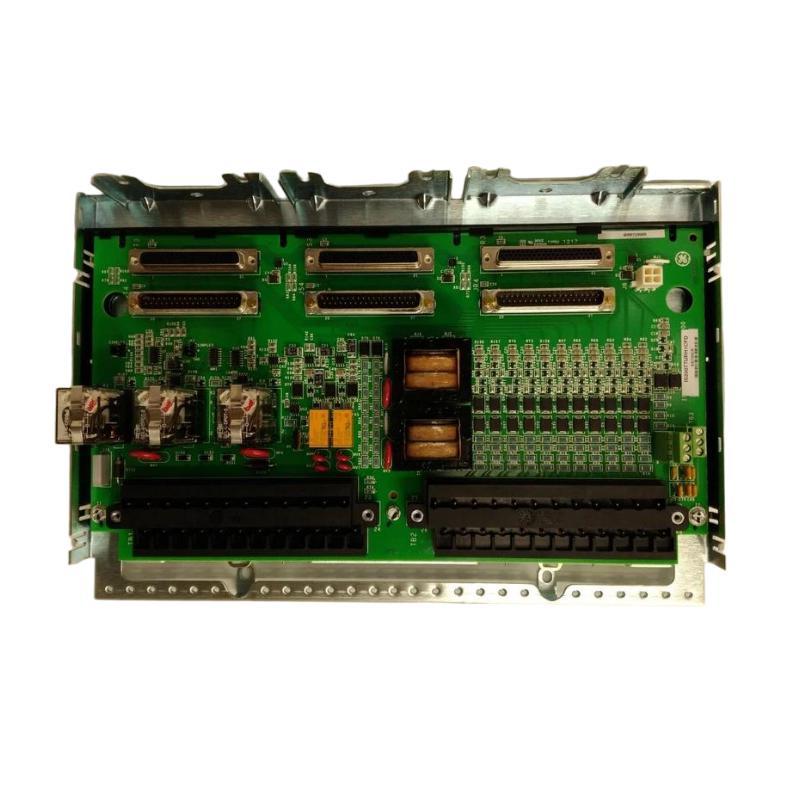
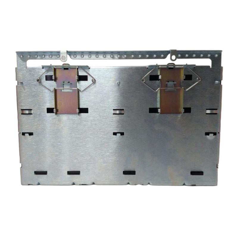
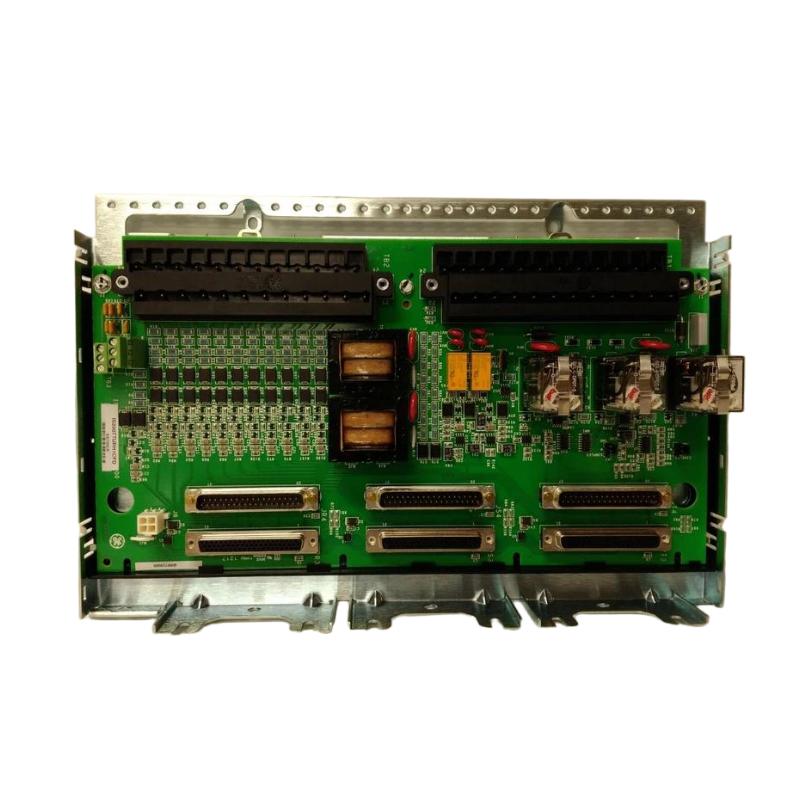
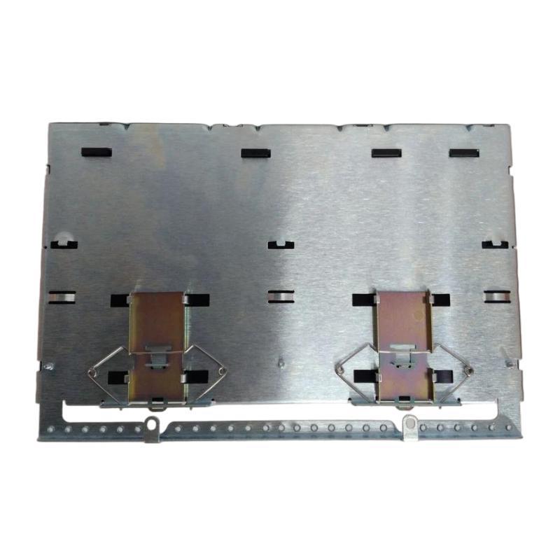
- GE
- IS230TNTRHIC
- Controller Module
- USA
- 220 × 150 × 30 mm
- 1 kg
- Xiamen, China
- New & In Stock
- T/T, PayPal, Western Union
- 1 Year
- 1-3 Working Days
- DHL, UPS, TNT, FedEx and EMS.
- 24-Hour Service
- COO
- 39
Our advantage

Global Logistics
We have a 10-year logistics and express cooperation agreement, so our products can be shipped to any place in the world.

Brand new and original
Our products are imported in bulk from the place of origin. Because of the cooperative relationship, our products are all original and 100% new.

24-hour service
We provide 7*24 hours service to our customers. We will be there whenever you need us.

Price advantage
All our products are priced very favorably because we have our own warehouse and supply.
| Company Information | |||
| [email protected] | |||
| Mobile | +8615980777398 | ||
| +8615980777398 | |||
| 15980777398 |
Product Overview
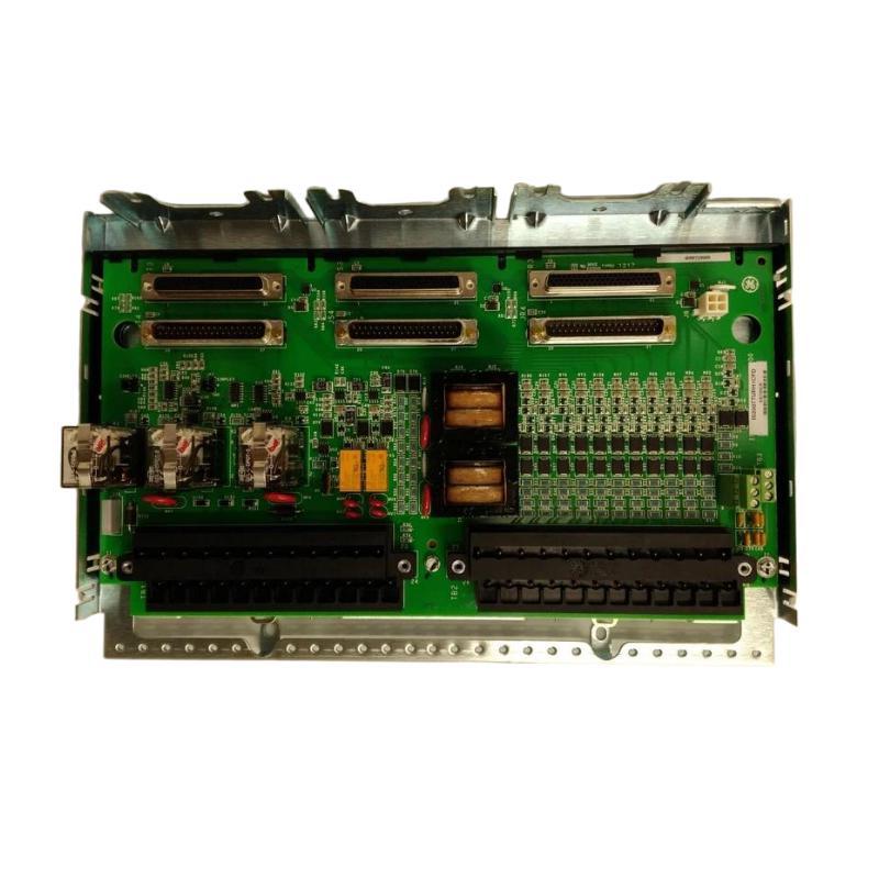
The GE IS230TNTRHIC Controller Module is an industrial control component identified for use in compatible GE automation and control systems. Controller-related hardware plays an important role in industrial installations by supporting the processing, coordination, or interface functions required for automated equipment operation. The precise function of the IS230TNTRHIC depends on its hardware design and the control architecture in which it is installed.
Industrial control systems rely on coordinated operation between controllers, interface assemblies, communication hardware, power distribution components, and field devices. Each component must be correctly identified and installed to maintain the intended system configuration. A suitable controller module can contribute to dependable equipment operation when its specifications and application match the requirements of the host system.
The GE IS230TNTRHIC designation should be verified against the product label and original equipment records before procurement or replacement. The model number provided identifies the requested product, but detailed information such as processor capabilities, memory capacity, communication protocols, I/O channel counts, and supported firmware should not be assumed without confirmation from the applicable technical documentation.
With listed dimensions of 220 × 150 × 30 mm and a weight of approximately 1 kg, the module can be included in industrial cabinet layout planning, spare-parts management, and equipment maintenance activities.
Technical Specifications
| Parameter | Specification |
|---|---|
| Manufacturer | General Electric (GE) |
| Model Number | IS230TNTRHIC |
| Product Type | Controller Module |
| Product Family | GE IS230 Industrial Control Hardware |
| Primary Application | Industrial automation and control |
| Control Function | Verify against the designated host-system configuration |
| Processor Type | Not confirmed |
| Memory Capacity | Not confirmed |
| Communication Interfaces | Not confirmed |
| I/O Capability | Not confirmed |
| Dimensions | 220 × 150 × 30 mm |
| Weight | 1 kg |
| Installation | Compatible industrial control equipment |
| Replacement Requirement | Confirm part number, revision, configuration, and system compatibility |
Note: The specifications above preserve the supplied product identification, dimensions, and weight. Model-specific electrical ratings, processor details, communication interfaces, and control capabilities should be verified against the actual module and its applicable equipment documentation.
What Is the GE IS230TNTRHIC Controller Module?
A controller module is a hardware component used within an industrial automation architecture to perform a designated control-related function. Depending on the system design, controller hardware may execute programmed logic, coordinate equipment operation, process signals, or exchange information with other components.
The exact role of a particular module cannot be determined from the word “controller” alone. Industrial control platforms can contain several types of assemblies that differ in their processing capabilities, interfaces, and intended installation locations.
For the GE IS230TNTRHIC, the complete product designation and the host equipment’s parts documentation should be used to establish its specific purpose. This distinction is important when selecting replacements because modules with similar dimensions or product-family designations may have different electrical functions.
Correct identification helps maintenance teams avoid unsuitable substitutions, preserve the original system configuration, and reduce the risk of commissioning problems.
Function and Working Principle
The working principle of a controller module depends on the hardware architecture in which it operates. In a typical industrial automation system, control-related hardware participates in a sequence that connects process information with programmed control actions.
Process Information Acquisition
Industrial systems receive information from sensors, switches, transmitters, and other field devices. This information describes equipment status or process conditions and is supplied to the appropriate control hardware through designated interfaces.
The specific input types and signal-processing capabilities supported by the IS230TNTRHIC must be confirmed from its technical documentation.
Control Logic and Decision-Making
Where a module is designed to execute control logic, programmed instructions are used to evaluate operating conditions and determine the required system response. The control strategy may involve sequencing, interlocking, monitoring, or other application-specific functions.
The actual processing role of the IS230TNTRHIC should not be assumed without confirming its documented function.
Communication and Coordination
Industrial automation equipment often exchanges operating information with other controllers, interface assemblies, drives, or supervisory systems. Communication methods vary between platforms and hardware versions.
The communication capabilities of this particular module must be verified before connecting it to a network or another control device.
Control-System Response
Based on the configured system architecture, control hardware may support commands, alarms, status updates, or other automation functions. The resulting action depends on the application logic and the capabilities of the associated equipment.
Correct configuration and compatible hardware are essential for predictable system behavior.
Role in Industrial Control Systems
Industrial control systems combine hardware and software to monitor processes, coordinate equipment, and respond to changing operating conditions. A typical installation may contain several functional layers:
- Control hardware: Performs the designated processing or control functions.
- Input and output interfaces: Connect the control system with field signals.
- Communication components: Exchange information between compatible devices.
- Power distribution: Supplies electrical power to the installed equipment.
- Field instrumentation: Measures process conditions and equipment status.
- Actuation equipment: Carries out commands through motors, valves, or other devices.
- Operator interface: Presents system status, alarms, and operating information.
The IS230TNTRHIC should be assigned its place in this architecture only after its exact function has been confirmed. Proper integration depends on using the module in the intended equipment position and following the original system design.
Incorrect module selection, unsupported configuration changes, or wiring errors can affect the operation of connected equipment. Accurate identification and documented installation procedures are therefore essential.
Industrial Applications
Industrial Automation
Industrial automation installations use control hardware to coordinate machine sequences, monitor equipment conditions, and support production processes. A compatible controller-related module may form part of the wider control architecture.
Manufacturing Systems
Manufacturing facilities often contain interconnected control equipment for assembly, material handling, inspection, and process coordination. Maintaining the correct hardware configuration helps support reliable operation and planned maintenance.
Process Industries
Water treatment, chemical processing, utilities, and other process environments use control systems to monitor operating variables and coordinate equipment. Component compatibility is especially important where multiple control layers operate together.
Power Generation and Plant Equipment
Industrial power facilities may rely on specialized control hardware for equipment monitoring, coordination, and process management. Any replacement module must be verified against the intended equipment configuration.
Industrial Equipment Refurbishment
During refurbishment, obsolete or damaged control hardware may need to be inspected and replaced. Confirming the full model number and revision helps technicians identify an appropriate component and avoid unsupported substitutions.
These are general industrial automation contexts. The suitability of the IS230TNTRHIC for a particular application must be established from its documented function and the requirements of the target system.
Installation and System Integration
Correct installation helps protect equipment, maintain system integrity, and simplify future maintenance. Work should be performed by qualified personnel following the approved procedures for the host control system.
1. Verify the Product Identification
Before installing the module, confirm the complete model number and any revision or suffix markings. Compare the replacement with the original component and the equipment’s approved parts list.
Check the following details:
- Complete part number.
- Hardware revision.
- Product label and board markings.
- Connector arrangement.
- Mounting configuration.
- Intended installation location.
- Associated hardware and software requirements.
Do not assume that a similar-looking module is compatible simply because it belongs to the same product family.
2. Isolate the Equipment
Follow the site’s approved shutdown and lockout/tagout procedures before opening the control cabinet or removing installed hardware. Isolate the relevant power sources and verify the absence of hazardous voltage.
Observe any required discharge periods for equipment that may retain stored electrical energy. Follow the applicable safety instructions before touching connectors or internal assemblies.
3. Inspect the Installation Area
Before fitting the replacement, inspect the mounting area for damage, contamination, loose hardware, restricted access, and signs of overheating.
The module’s listed dimensions are 220 × 150 × 30 mm. Confirm that the cabinet provides adequate physical space and the required clearance for wiring, cooling, and maintenance access.
4. Document Existing Connections
Record the existing connection arrangement before disconnecting wiring. Use approved diagrams and conductor labels to identify each connection.
Do not infer terminal assignments from the appearance of the module or from diagrams belonging to another model.
5. Install and Secure the Module
Use the mounting method specified for the actual hardware. Ensure that the module is properly seated and secured without forcing connectors or mounting features into position.
Check that nearby components do not obstruct the installation and that wiring remains accessible for inspection.
6. Verify Configuration and Connections
Where the module requires configuration, firmware, addressing, or application-specific settings, follow the procedures specified for the host system. Confirm that all connections match the approved wiring documentation.
Do not load unsupported firmware or transfer configuration data from another model without confirming compatibility.
7. Complete Commissioning Checks
Before returning the equipment to service, verify:
- Correct module identification.
- Secure mechanical installation.
- Correct connection placement.
- Proper connector engagement.
- Required configuration settings.
- Absence of visible damage or loose hardware.
- Completion of required safety checks.
Follow the host system’s prescribed startup and commissioning procedure, then review the available diagnostics before resuming normal operation.
Troubleshooting and Fault Diagnosis
A fault involving controller-related hardware may originate in the module, its connections, its configuration, or another part of the automation system. A structured diagnostic approach helps avoid unnecessary component replacement.
Controller Module Is Not Recognized
Possible causes:
- Incorrect replacement model or revision.
- Loose or improperly seated connectors.
- Power supply problems.
- Unsupported configuration or firmware.
- A fault in the associated backplane or interface hardware.
Recommended checks:
- Review the controller system’s diagnostic messages.
- Confirm the complete module identification.
- Inspect the installation and connections after safely isolating the equipment.
- Verify power and interface requirements using the approved documentation.
- Investigate associated hardware if the module remains unrecognized.
System Stops Operating After Replacement
Possible causes:
- Incorrect hardware selection.
- Wiring restored incorrectly.
- Configuration mismatch.
- Disturbed connections to adjacent modules.
- An unrelated system fault.
Recommended checks:
- Review the fault history and available system diagnostics.
- Compare the installed component with the original parts record.
- Check all connections against the approved wiring diagram.
- Verify configuration compatibility.
- Follow the host system’s prescribed recovery procedure.
Intermittent Operation
Intermittent problems may result from loose connections, vibration, damaged conductors, unstable power, environmental conditions, or faults in associated hardware.
Inspect the mounting and connection arrangement according to the approved maintenance procedure. Check environmental conditions and review fault records for recurring patterns.
Communication Errors
If the module participates in a communication path, errors may result from incorrect configuration, damaged cables, connection problems, network faults, or incompatible hardware.
First confirm whether the IS230TNTRHIC supports the communication interface involved. Then follow the applicable diagnostic procedure instead of assuming that every communication fault originates in the module.
Overheating or Physical Damage
Discoloration, burn marks, cracked components, corrosion, or damaged connectors may indicate a serious equipment problem.
Do not return visibly damaged hardware to service without determining the cause. Inspect associated connections and equipment, and replace the affected component according to the approved maintenance procedure.
Maintenance Recommendations
Preventive maintenance can help preserve the condition of industrial control hardware and reduce avoidable downtime.
Routine Visual Inspection
Inspect the module and surrounding equipment for physical damage, contamination, corrosion, loose mounting features, and signs of overheating. Set inspection intervals according to the operating environment and the facility’s maintenance plan.
Connection and Wiring Checks
Inspect accessible connectors and wiring for damage, loose retention, abrasion, or other abnormalities. Follow approved procedures when disconnecting or reconnecting conductors.
Environmental Management
Maintain the cabinet within the environmental limits specified for the installed equipment. Excessive heat, dust, moisture, vibration, and corrosive substances can affect hardware reliability.
Configuration Records
Maintain records of the installed part number, hardware revision, configuration changes, firmware information where applicable, and replacement history. Accurate records can shorten future troubleshooting and procurement activities.
Spare-Part Storage
Store replacement hardware in a clean, dry environment using suitable protective packaging. Apply electrostatic-discharge precautions where required and preserve the product identification labels.
Planned Replacement
Replace damaged or unreliable hardware according to the maintenance plan and approved system procedures. Before installation, confirm that the replacement matches the intended application and configuration.
Compatible System Components
A controller module may operate within a larger control architecture containing several types of hardware. The actual components used with the IS230TNTRHIC must be verified for the target installation.
| Component Category | General Function |
|---|---|
| Control Processor | Executes designated control logic |
| Input Modules | Receive signals from compatible field devices |
| Output Modules | Provide designated control outputs |
| Interface Assemblies | Connect system components through specified interfaces |
| Communication Hardware | Transfers data between supported devices |
| Power Supply | Provides electrical power to compatible equipment |
| Backplane or Mounting Assembly | Supports installation and interconnection where applicable |
| Field Instrumentation | Measures process variables or equipment status |
| Operator Interface | Displays operating conditions and diagnostic information |
This table describes common categories within industrial control systems; it is not a verified list of products compatible with the IS230TNTRHIC. Confirm all hardware combinations against the original equipment documentation before installation.
Replacement and Procurement Considerations
Selecting a replacement GE IS230TNTRHIC Controller Module requires more than matching its physical dimensions. The complete product identity and intended application must be confirmed.
| Verification Item | Importance |
|---|---|
| Full Model Number | Confirms the requested component |
| Revision or Suffix | Identifies possible hardware differences |
| Electrical Function | Establishes the module’s intended role |
| Connector Arrangement | Helps prevent connection errors |
| Configuration Requirements | Confirms software or firmware compatibility where applicable |
| Host Equipment | Establishes the intended installation |
| Physical Condition | Helps assess the suitability of the replacement |
| Testing Documentation | Provides evidence of inspection or functional testing where available |
| Warranty Terms | Supports purchasing and maintenance planning |
The supplied dimensions are 220 × 150 × 30 mm, and the listed weight is 1 kg. These details support cabinet layout, shipping, handling, and inventory planning but do not establish electrical or functional compatibility.
For refurbished or surplus equipment, review the physical condition, labeling, and available testing records. Confirm the exact part number and revision before ordering, especially when replacing hardware in an existing installation.
Key Advantages
Industrial Control Integration
When correctly matched to its intended system, the module can form part of a structured industrial control installation.
Compact Physical Profile
The listed dimensions of 220 × 150 × 30 mm help maintenance teams evaluate cabinet space and plan equipment replacement.
Practical Spare-Part Management
A clearly documented model designation supports inventory tracking, replacement planning, and equipment records.
Maintainability
Proper identification and documented installation procedures help technicians inspect, replace, and troubleshoot control hardware more efficiently.
Reduced Compatibility Risk
Checking the complete part number, revision, and host-system requirements helps prevent incorrect substitutions and avoidable commissioning problems.
Technical FAQs
What is the GE IS230TNTRHIC Controller Module?
The GE IS230TNTRHIC is identified as a Controller Module for industrial automation and control applications. Its precise processing or interface role should be verified from the actual unit markings and applicable equipment documentation.
What are the dimensions of the IS230TNTRHIC?
The listed dimensions are 220 × 150 × 30 mm.
How much does the module weigh?
The supplied weight is approximately 1 kg.
What communication protocols does the IS230TNTRHIC support?
The supported communication interfaces and protocols have not been confirmed from the supplied product information. Check the applicable technical documentation before connecting the module to a network.
Does the module include digital or analog I/O?
The specific I/O capabilities have not been established here. Verify the module’s documented function and electrical specifications before designing or modifying connections.
Can another GE IS230 module replace the IS230TNTRHIC?
Not automatically. Compatibility depends on the exact function, revision, interfaces, configuration requirements, and host equipment. Similar dimensions or product-family names are not sufficient evidence of interchangeability.
What should be checked if the module is not recognized?
Review system diagnostics, verify the full part number, inspect connections under safe conditions, and confirm the required power and configuration. If the problem persists, investigate associated interface hardware and the wider control system.
How can the module’s service life be supported?
Routine inspection, suitable cabinet conditions, correct installation, documented configuration changes, and accurate spare-part records can help support long-term equipment maintenance.
Conclusion
The GE IS230TNTRHIC Controller Module is an industrial control component identified for integration into compatible automation equipment. With listed dimensions of 220 × 150 × 30 mm and a weight of approximately 1 kg, it can be included in industrial spare-parts planning, cabinet layout assessments, and equipment maintenance procedures.
Reliable operation depends on confirming the module’s exact function, matching the full part number and revision, following the correct installation procedure, and verifying all associated connections and configuration requirements. Processor specifications, communication capabilities, and I/O functions should be confirmed rather than inferred from the product designation.
For replacement and maintenance work, accurate hardware identification, systematic troubleshooting, appropriate environmental control, and complete maintenance records help support safe installation and dependable industrial control-system operation.