

ProductPRODUCT
Featured products



Contact Us
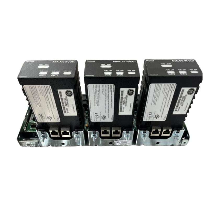
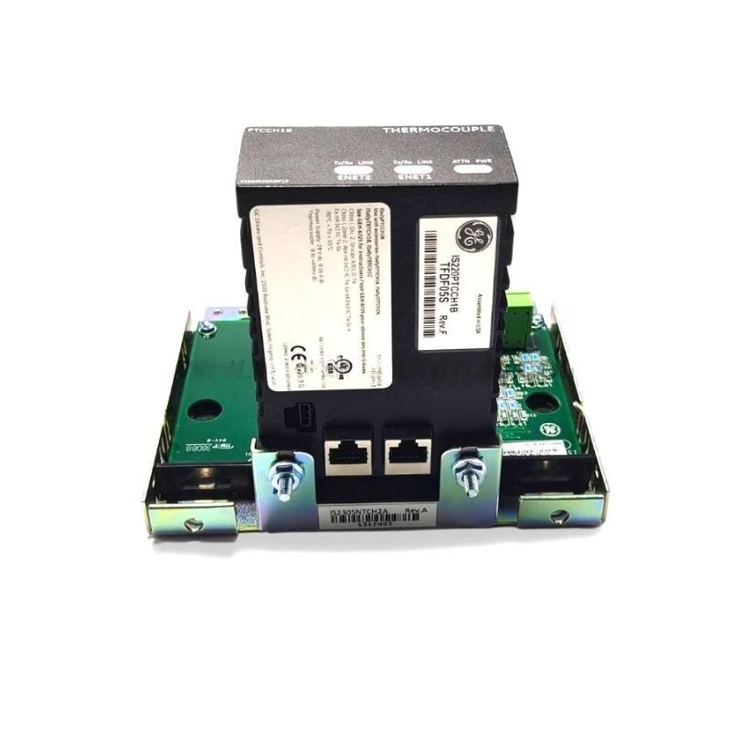
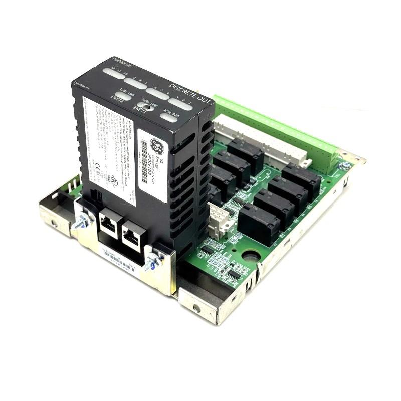
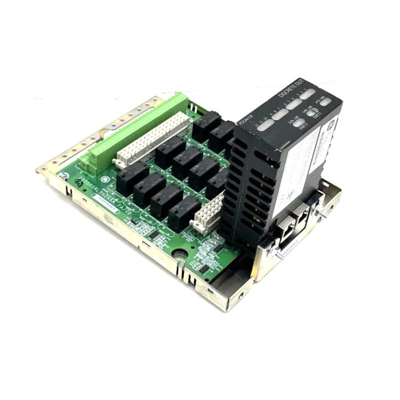
- GE
- IS230TNTRH1C
- DIN Rail Module
- USA
- 162 x 115 x 72 mm
- 1 kg
- Xiamen, China
- New & In Stock
- T/T, PayPal, Western Union
- 1 Year
- 1-3 Working Days
- DHL, UPS, TNT, FedEx and EMS.
- 24-Hour Service
- COO
- 20
Our advantage

Global Logistics
We have a 10-year logistics and express cooperation agreement, so our products can be shipped to any place in the world.

Brand new and original
Our products are imported in bulk from the place of origin. Because of the cooperative relationship, our products are all original and 100% new.

24-hour service
We provide 7*24 hours service to our customers. We will be there whenever you need us.

Price advantage
All our products are priced very favorably because we have our own warehouse and supply.
| Company Information | |||
| [email protected] | |||
| Mobile | +8615980777398 | ||
| +8615980777398 | |||
| 15980777398 |
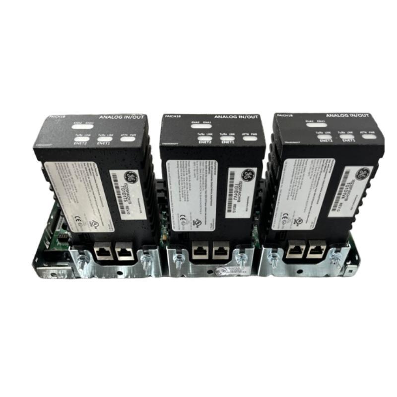
Product Overview
The GE IS230TNTRH1C DIN Rail Module is an industrial control hardware component designed for installation within compatible automation and control equipment. DIN rail-mounted assemblies are widely used in industrial electrical cabinets because they provide a structured mounting arrangement for control components, simplify equipment organization, and support convenient inspection and maintenance.
In industrial automation environments, reliable hardware installation is essential for maintaining system stability and reducing unnecessary downtime. Components mounted within control cabinets must be correctly identified, securely installed, and compatible with the surrounding equipment. The GE IS230TNTRH1C should therefore be selected and installed according to its designated role in the original control-system configuration.
The IS230TNTRH1C belongs to the GE IS230 hardware designation family. However, its exact electrical function, internal configuration, terminal arrangement, and compatible host equipment should be confirmed from the installed unit’s markings and the applicable equipment documentation. The model designation alone should not be used to infer unsupported electrical specifications or interchangeability with other GE modules.
With listed dimensions of 162 × 115 × 72 mm and a weight of approximately 1 kg, the GE IS230TNTRH1C is a practical component to include in industrial spare-parts inventories, equipment replacement plans, and control-cabinet layout assessments.
Technical Specifications
| Parameter | Specification |
|---|---|
| Manufacturer | General Electric (GE) |
| Model Number | IS230TNTRH1C |
| Product Type | DIN Rail Module |
| Product Family | GE IS230 Industrial Control Hardware |
| Primary Application | Industrial automation and control equipment |
| Mounting Arrangement | Verify the specified mounting method for the installed assembly |
| Dimensions | 162 × 115 × 72 mm |
| Weight | 1 kg |
| Installation Environment | Compatible industrial control cabinet or equipment enclosure |
| System Integration | Dependent on the designated host equipment |
| Replacement Requirement | Verify complete part number, revision, connectors, and application compatibility |
| Maintenance Focus | Mounting security, physical condition, wiring, and connection integrity |
Note: Specific electrical ratings, communication interfaces, I/O functions, terminal assignments, and environmental limits have not been established by the supplied product information. Confirm these details before installation or replacement.
What Is the GE IS230TNTRH1C?
The GE IS230TNTRH1C is identified as a DIN Rail Module used in an industrial control hardware context. DIN rail mounting is a common approach for securing compatible electrical and electronic assemblies inside cabinets, allowing individual components to be arranged in a defined layout.
A DIN rail module may serve different functions depending on its design. Some assemblies provide electrical termination, signal interfacing, control-system connections, or other supporting functions. These roles are not interchangeable, so the specific function of the IS230TNTRH1C must be verified before it is incorporated into a system.
Correct component identification is particularly important in industrial installations containing multiple modules with similar housings. A visually similar component may have different wiring requirements, electrical characteristics, or system compatibility.
For maintenance personnel, the most important initial checks are the complete model designation, revision information, mounting configuration, connector arrangement, and the position of the module within the original equipment.
Function and Working Principle
Hardware Integration
Industrial control systems contain a combination of processing hardware, electrical interfaces, power distribution components, communication devices, and field connections. A designated mounting module can contribute to the physical and electrical organization of this equipment.
The exact contribution of the IS230TNTRH1C depends on its documented function within the host system. Its operation should not be assumed to match that of another module solely because both belong to the GE IS230 family.
Mechanical Mounting
DIN rail-based installation allows compatible components to be secured in an organized cabinet arrangement. Proper mounting helps prevent unwanted movement and maintains suitable access to adjacent components and wiring.
The mounting method should always match the actual hardware design. If the module uses a specialized bracket, carrier, or other retention arrangement, the specified installation procedure takes precedence over generic DIN rail practices.
Electrical Interface and Connections
Where the installed assembly includes electrical terminals or connectors, these connections must be made according to the approved wiring diagram. Incorrect connections can result in malfunction, signal interruption, or damage to connected equipment.
The exact terminal layout and electrical function of the IS230TNTRH1C should be established from the applicable documentation rather than inferred from its product name.
Support for Equipment Maintenance
A correctly identified and installed module helps technicians maintain the intended equipment arrangement. Accurate labeling, accessible connections, and documented replacement procedures can simplify troubleshooting and reduce maintenance errors.
Role in Industrial Automation Systems
Industrial automation systems coordinate machinery and processes through a combination of controllers, interfaces, electrical connections, sensors, actuators, and operator interfaces.
A typical control architecture may include:
- Control processor: Executes programmed control logic.
- Interface hardware: Provides designated connections between system components.
- Power distribution: Supplies power to compatible control devices.
- Communication equipment: Transfers information between devices where required.
- Field devices: Provide measurements, status signals, or physical control actions.
- Operator interface: Presents operating information and diagnostic messages.
The IS230TNTRH1C should be assigned a role within this architecture only after its function has been confirmed for the target installation.
Correct hardware integration is important because industrial control systems rely on compatible components working together according to a defined electrical and mechanical design. An incorrect replacement can cause installation difficulties or introduce faults even when the component appears physically similar to the original.
Industrial Applications
Industrial Control Cabinets
Control cabinets house the components used to monitor and operate industrial equipment. A correctly specified module can be installed in the designated cabinet arrangement, helping maintain a structured and serviceable hardware layout.
Manufacturing Automation
Manufacturing facilities use industrial control hardware to coordinate production equipment, material movement, machine sequences, and process monitoring. Maintaining the original hardware configuration helps support reliable maintenance and equipment restoration.
Process Control Facilities
Water treatment, chemical processing, utilities, and other process industries rely on interconnected control hardware to monitor operating conditions and manage equipment. Correct component identification is essential when replacing modules in these installations.
Power Generation and Industrial Utilities
Industrial utility installations may contain extensive control cabinets and specialized equipment assemblies. Replacement work should follow the original equipment documentation to preserve the intended configuration.
Equipment Refurbishment
During industrial equipment refurbishment, technicians may inspect, replace, or reorganize control hardware. Confirming the exact model and installation requirements helps reduce the risk of using an unsuitable replacement.
These examples describe general industrial control environments. The suitability of the IS230TNTRH1C for a particular application must be confirmed from its documented function and intended host equipment.
Installation and System Integration
Proper installation helps maintain mechanical stability, electrical safety, and long-term equipment serviceability. Work should be performed by qualified personnel using the approved procedures for the relevant control system.
1. Verify the Module Identification
Before installing a replacement, compare the original component with the proposed unit. Check:
- Complete model number: IS230TNTRH1C.
- Revision or suffix information.
- Manufacturer and product markings.
- Connector and terminal arrangement.
- Mounting features.
- Existing installation location.
- Associated hardware and host-system requirements.
Do not assume that another GE module is interchangeable based on dimensions or product-family naming alone.
2. Isolate the Equipment
Follow the site’s approved shutdown and lockout/tagout procedures before opening the cabinet or disconnecting the module. Isolate relevant power sources and verify the absence of hazardous voltage.
Some industrial equipment may retain stored energy after power has been disconnected. Follow the host equipment’s safety instructions before handling terminals, connectors, or internal assemblies.
3. Inspect the Mounting Area
Examine the mounting location for:
- Damaged rails, brackets, or retaining features.
- Loose mounting hardware.
- Dust, moisture, or other contamination.
- Restricted access to neighboring components.
- Signs of overheating or corrosion.
- Insufficient clearance for wiring and maintenance.
The listed module dimensions are 162 × 115 × 72 mm. Confirm that the available cabinet space and required clearances are appropriate for the actual installation.
4. Install the Module Correctly
Use the specified mounting arrangement for the component. Ensure that the module is seated securely and that all required retaining features are engaged.
Avoid forcing the component into place. Resistance may indicate incorrect positioning, an incompatible mounting arrangement, or interference from adjacent equipment.
5. Verify Connections
If the module includes electrical connectors or associated wiring, document the existing arrangement before disconnecting conductors. Restore each connection according to the approved wiring diagram and applicable terminal identification.
Check connector engagement, conductor condition, wire labeling, and cable routing. Do not guess terminal assignments based on physical appearance.
6. Complete Pre-Commissioning Checks
Before restoring the equipment to service, verify:
- Correct part identification.
- Secure mechanical installation.
- Correct connection placement.
- Proper connector engagement.
- No loose wires or foreign objects.
- No visible physical damage.
- Completion of required safety and inspection checks.
Follow the host equipment’s commissioning procedure before returning the system to normal operation.
Troubleshooting and Fault Diagnosis
A problem involving a DIN rail module may originate from the component itself, the mounting arrangement, associated wiring, or another part of the control system. A structured diagnostic process helps avoid unnecessary replacement.
Module Does Not Fit or Remain Secure
Possible causes:
- Incorrect mounting arrangement.
- Damaged rail or retaining hardware.
- Incorrect replacement model.
- Missing mounting accessories.
- Interference from adjacent equipment.
Recommended checks:
- Isolate the equipment before inspection.
- Compare the mounting features with the original module.
- Inspect the rail, brackets, and retention mechanism.
- Confirm the complete replacement part number.
- Replace damaged mounting hardware according to the equipment design.
System Fault After Replacement
Possible causes:
- Incorrect part or hardware revision.
- Loose or incorrectly restored connections.
- Disturbed neighboring wiring.
- Incorrect module positioning.
- An unrelated fault in the control system.
Recommended checks:
- Review the system’s diagnostic messages.
- Verify the installed model and revision.
- Compare wiring against the approved diagram.
- Inspect accessible connections under safe, isolated conditions.
- Follow the prescribed diagnostic procedure for the host equipment.
Intermittent Operation
Intermittent problems may be associated with loose connections, damaged conductors, vibration, contamination, or faults in associated hardware.
Inspect the mounting arrangement and connections according to the approved maintenance procedure. Check cable routing and strain relief where applicable. Do not manipulate energized connections unless the equipment documentation specifically permits it.
Visible Damage or Overheating
Cracks, corrosion, discoloration, melted insulation, or burn marks may indicate an unsafe condition or an underlying electrical fault.
Do not return visibly damaged hardware to service without determining the cause. Inspect associated wiring and equipment, and replace the affected component according to the approved procedure.
Uncertain Module Function
If the precise function of the IS230TNTRH1C cannot be confirmed, stop the installation process until the component has been positively identified. Guessing its electrical role or substituting a similar-looking module can introduce additional faults.
Maintenance Recommendations
A preventive maintenance program can help preserve the physical condition and serviceability of industrial control hardware.
Routine Visual Inspection
Inspect the module for visible damage, contamination, corrosion, loose mounting features, and signs of abnormal heating. Inspection intervals should reflect the operating environment and the facility’s maintenance plan.
Mounting Security
Check the mounting arrangement for movement, damaged retention features, or loosened hardware. Any adjustment should follow the specified maintenance procedure.
Wiring and Connector Inspection
Where applicable, inspect associated wiring for damaged insulation, loose connections, abrasion, and excessive mechanical strain. Verify that connectors remain properly engaged.
Environmental Management
Maintain suitable cabinet conditions within the limits specified for the installed equipment. Excessive dust, moisture, heat, and vibration can shorten the service life of industrial hardware.
Maintenance Documentation
Record the installed part number, revision, equipment location, inspection findings, and replacement history. Accurate records help technicians identify the correct spare part during future maintenance.
Spare-Part Storage
Store replacement hardware in a clean, dry environment with appropriate packaging. Protect exposed connectors and follow any electrostatic-discharge precautions required for the component.
Compatible System Components
The GE IS230TNTRH1C may be installed as part of a larger industrial control assembly. Depending on the host equipment, the surrounding system may include the following categories of components.
| Component Category | General Function |
|---|---|
| Control Processor | Executes configured control logic |
| Interface Hardware | Provides designated connections between system components |
| Terminal Assemblies | Organize electrical termination where applicable |
| Power Distribution Equipment | Supplies power to compatible devices |
| Communication Hardware | Transfers control or status information where required |
| Field Wiring | Connects control hardware to external equipment |
| Sensors and Switches | Provide measurements or equipment status |
| Actuators and Controlled Devices | Perform designated physical actions |
| Operator Interface | Displays operating information and diagnostic messages |
This is a general overview of industrial control architecture, not a verified compatibility list for the IS230TNTRH1C. Exact compatible modules and accessories must be confirmed against the original system documentation.
Replacement and Procurement Considerations
When sourcing a replacement GE IS230TNTRH1C DIN Rail Module, exact identification and application compatibility should take priority over physical similarity.
| Verification Item | Importance |
|---|---|
| Complete Model Number | Confirms the requested component identity |
| Hardware Revision | Helps identify configuration differences |
| Product Markings | Supports positive identification |
| Mounting Configuration | Ensures the component fits the designated installation |
| Connector Arrangement | Helps prevent connection errors |
| Host Equipment | Establishes the intended application |
| Physical Condition | Helps identify damaged or unsuitable stock |
| Testing and Warranty Information | Supports procurement and maintenance planning |
The listed dimensions are 162 × 115 × 72 mm, and the listed weight is 1 kg. These measurements are useful for cabinet layout, handling, storage, and shipping calculations. They do not independently establish electrical compatibility.
Before ordering, verify the exact product designation, revision, and intended installation. For refurbished or surplus hardware, review the physical condition and any available functional test documentation.
Key Advantages
Organized Equipment Installation
A correctly specified module can be integrated into the designated cabinet arrangement, supporting a structured layout of industrial control hardware.
Practical Maintenance Planning
The documented model number, dimensions, and weight support spare-parts identification, inventory control, and installation planning.
Improved Serviceability
Secure mounting and clearly documented connections can simplify inspection and replacement activities.
Support for Industrial Control Integration
When matched to the correct host equipment, the module can contribute to maintaining the intended configuration of an industrial control assembly.
Reduced Replacement Errors
Verifying the complete part number and revision helps prevent the installation of physically similar but incompatible components.
Technical FAQs
What is the GE IS230TNTRH1C?
The GE IS230TNTRH1C is identified as a DIN Rail Module for industrial control equipment. Its precise electrical function should be confirmed using the actual component markings and the applicable host-system documentation.
What are the dimensions of the IS230TNTRH1C?
The listed dimensions are 162 × 115 × 72 mm.
How much does the module weigh?
The listed weight is approximately 1 kg.
What is the main purpose of a DIN rail module?
DIN rail modules are designed for integration into equipment using a designated mounting arrangement. Depending on the specific product, they may support electrical interfaces, control hardware installation, or other system functions.
Can another GE IS230 module replace the IS230TNTRH1C?
Not automatically. The complete model number, revision, electrical function, mounting configuration, and host-system requirements must be verified before substitution.
What should be checked before installation?
Confirm the product identification, mounting features, connector arrangement, wiring documentation, and intended installation position. Follow the approved electrical isolation and commissioning procedures.
What can cause problems after replacing the module?
Possible causes include incorrect hardware, poor mechanical installation, loose or incorrectly restored connections, damaged wiring, or faults elsewhere in the control system.
Are electrical ratings and communication interfaces specified here?
No model-specific electrical ratings or communication details have been established from the supplied product information. These specifications should be confirmed from the component markings and applicable equipment documentation.
Conclusion
The GE IS230TNTRH1C DIN Rail Module is an industrial control hardware component identified for use in compatible automation and control installations. With listed dimensions of 162 × 115 × 72 mm and a weight of approximately 1 kg, it can be incorporated into spare-parts planning, cabinet-space assessment, and equipment maintenance procedures.
Reliable installation depends on confirming the component’s exact function, verifying the complete part number and revision, using the specified mounting arrangement, and following the approved procedures for associated connections. Physical dimensions alone are not sufficient to establish compatibility with another module.
For replacement and maintenance projects, careful identification, secure installation, systematic fault diagnosis, and accurate maintenance records help support safe servicing and dependable operation of industrial control equipment.