

ProductPRODUCT
Featured products



Contact Us
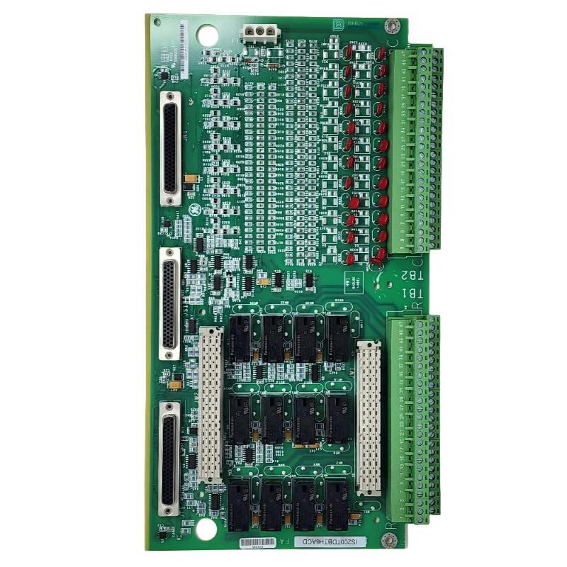
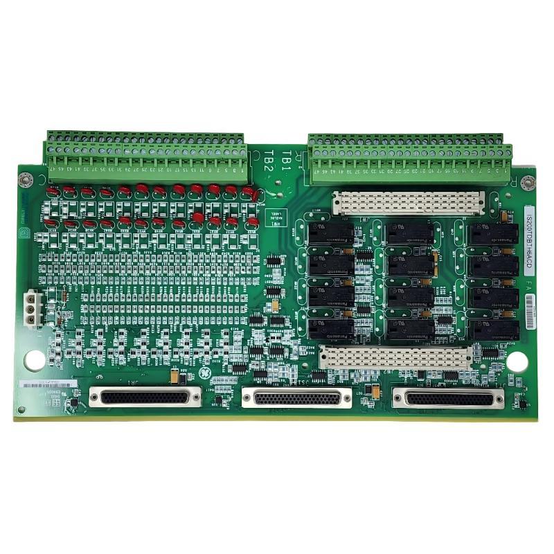
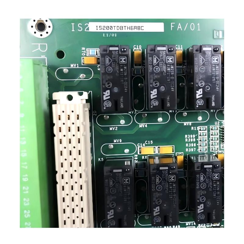
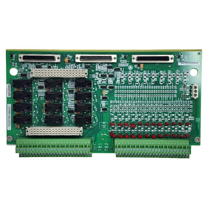
- GE
- IS230TDBTH6A IS200TDBTH6ABC
- Discrete I/O Boards
- USA
- 220 x 100 x 50 mm
- 0.6 kg
- Xiamen, China
- New & In Stock
- T/T, PayPal, Western Union
- 1 Year
- 1-3 Working Days
- DHL, UPS, TNT, FedEx and EMS.
- 24-Hour Service
- COO
- 23
Our advantage

Global Logistics
We have a 10-year logistics and express cooperation agreement, so our products can be shipped to any place in the world.

Brand new and original
Our products are imported in bulk from the place of origin. Because of the cooperative relationship, our products are all original and 100% new.

24-hour service
We provide 7*24 hours service to our customers. We will be there whenever you need us.

Price advantage
All our products are priced very favorably because we have our own warehouse and supply.
| Company Information | |||
| [email protected] | |||
| Mobile | +8615980777398 | ||
| +8615980777398 | |||
| 15980777398 |
Product Overview
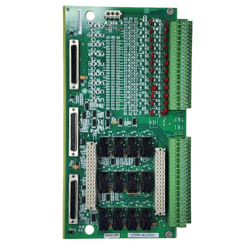
The GE IS230TDBTH6A / IS200TDBTH6ABC Discrete I/O Boards are industrial control interface assemblies intended for integration into compatible GE automation systems. Discrete input/output (I/O) hardware plays an important role in industrial control by providing the electrical interface between field devices and the control system. These signals allow controllers to monitor equipment conditions, receive operator commands, and coordinate the operation of machinery and auxiliary systems.
Discrete signals represent defined states rather than continuously varying measurements. Examples include a motor running or stopped, a valve open or closed, a limit switch activated or inactive, and an alarm present or cleared. Reliable acquisition and transmission of these states are essential for equipment sequencing, status monitoring, interlocking, and automated operating procedures.
Within an industrial control architecture, a discrete I/O board or its associated terminal interface helps organize field connections and establish the signal paths required by the system. The precise function of an individual assembly depends on its electrical design, connector configuration, and relationship with the host control hardware.
The supplied model identifiers are IS230TDBTH6A and IS200TDBTH6ABC. Their exact relationship and interchangeability should be confirmed against the existing installation and applicable equipment documentation before replacement. GE assemblies with similar designations can have different functions, terminal arrangements, or electrical characteristics.
With supplied dimensions of 220 × 100 × 50 mm and a weight of approximately 0.6 kg, these boards can be considered for industrial control cabinet integration and spare-parts planning. Correct identification, wiring, installation, and commissioning help support reliable signal connections and reduce avoidable control-system downtime.
Technical Specifications
| Parameter | Specification |
|---|---|
| Manufacturer | General Electric (GE) |
| Primary Model | IS230TDBTH6A |
| Related Model / Part Number | IS200TDBTH6ABC |
| Product Name | Discrete I/O Boards |
| Product Category | Industrial Control I/O Interface Assembly |
| Primary Function | Discrete signal interfacing, subject to configuration |
| Signal Category | Digital input/output signals |
| Dimensions | 220 × 100 × 50 mm |
| Weight | 0.6 kg |
| Installation | Designated position within compatible GE control equipment |
| System Role | Interface between field signal wiring and associated control hardware |
| Typical Applications | Industrial automation, equipment monitoring, and discrete control |
| Channel Count | Verify from the specific board documentation |
| Electrical Ratings | Verify from the applicable technical specifications |
| Host-System Compatibility | Confirm using the complete part number and system configuration |
| Replacement Requirements | Verify model, revision, connectors, wiring, and electrical characteristics |
The dimensions and weight are based on the supplied product information. The exact channel count, terminal layout, voltage ratings, current limits, isolation characteristics, and supported control-system hardware should be verified before installation.
Understanding GE Discrete I/O Boards
Discrete I/O boards are used in industrial automation systems to connect digital field signals with the control architecture. Depending on the design, an assembly may support input signals, output signals, or a defined combination of discrete circuit interfaces.
Input signals allow the control system to recognize the state of external devices. For example, a limit switch may indicate that a mechanism has reached its travel limit, while a contact may communicate the operating status of a motor or auxiliary device.
Output signals communicate commands from the controller to compatible external circuits. These commands may operate through an output module, relay interface, or other electrical switching arrangement appropriate to the application.
The board’s precise role must be established from its hardware documentation. The term Discrete I/O Boards does not, by itself, establish whether the particular assembly contains active electronic circuitry, serves primarily as a terminal interface, or performs another defined interconnection function.
For the GE IS230TDBTH6A / IS200TDBTH6ABC, correct product identification is therefore essential. Technicians should verify the assembly’s intended purpose and connection arrangement before integrating it into an existing control system.
Function and Working Principle
1. Discrete Signal Interface
The assembly supports the electrical connection of discrete signal circuits within a compatible control-system configuration. These circuits carry information about equipment states, operator actions, and process conditions.
A correctly installed interface helps maintain the intended electrical path between field wiring and the associated control hardware.
2. Input Signal Acquisition
Where the installed configuration supports discrete inputs, signals from external switches, sensors, or contacts can be transferred to the corresponding input electronics.
The control system interprets these signals according to its configured logic. For example, a controller may use an input state to determine whether a motor is ready to start or whether a valve has reached a required position.
The exact input circuitry and electrical thresholds depend on the associated hardware and must not be inferred from the model name alone.
3. Output Signal Distribution
Where discrete outputs are supported, the control system can issue commands to external circuits through the appropriate output hardware and wiring.
These commands may be used for equipment status indication, relay operation, or other defined control functions. The board should not be assumed to provide direct load-driving capability unless its specifications explicitly confirm that function.
4. Electrical Interconnection
Industrial control systems contain numerous conductors, connectors, and interface assemblies. A discrete I/O board helps establish the connections required by its designated system configuration.
Correct connector engagement, conductor identification, and adherence to wiring diagrams are important for maintaining reliable signal transmission.
5. Support for Diagnostics
A correctly configured discrete signal interface helps maintenance personnel trace signal paths and investigate abnormal operating states.
When a signal is missing or incorrect, technicians can check the field device, wiring, board connections, associated I/O electronics, and controller diagnostics to isolate the source of the fault.
Role in Industrial Control Systems
The GE IS230TDBTH6A / IS200TDBTH6ABC can form part of the signal interface architecture in a compatible GE industrial control system. Its role is to support the discrete electrical connections required for equipment monitoring and control.
A typical input path may be represented as:
Field Sensor or Switch → Wiring Interface → Input Electronics → Controller Logic
A typical output path may be represented as:
Controller Logic → Output Electronics → Wiring Interface → External Circuit
The exact arrangement depends on the board’s documented function and the architecture of the installed equipment.
Discrete signals are frequently used for:
- Equipment run and stop status
- Valve position monitoring
- Limit-switch detection
- Alarm and fault indication
- Operator push-button commands
- Equipment permissives
- Interlocking and sequence control
- Auxiliary system status
- Machine operating-state monitoring
In these applications, reliable signal connections are important because an incorrect state can affect the control sequence or the operator’s understanding of equipment conditions.
Industrial Applications
Power Generation
Power-generation installations rely on discrete signals to monitor auxiliary equipment, operating states, and equipment permissives. Correctly matched I/O interface hardware supports the integration of these signals into the wider control system.
Turbine and Generator Systems
Turbine and generator installations may contain extensive collections of limit switches, relay contacts, status signals, and discrete command circuits. A suitable interface assembly can form part of the associated control wiring architecture when approved for the installation.
Manufacturing Automation
Production equipment uses discrete signals to detect component positions, monitor machine states, and coordinate automatic sequences. Reliable I/O connections help maintain communication between field devices and control logic.
Process Automation
Industrial process facilities use digital signals to monitor pump status, valve position, equipment alarms, and auxiliary systems. These signals can support operating sequences and interlocks within the control architecture.
Industrial Machinery
Discrete signal interfaces are used in machinery that relies on switch contacts, digital sensors, and equipment status feedback. Correct board identification and wiring help simplify commissioning and future maintenance.
Control Cabinet Integration
Industrial cabinets often contain multiple control boards, I/O modules, terminal assemblies, power supplies, and communication components. A compatible discrete I/O board contributes to the organized connection of signal circuits within this environment.
These applications describe common uses of discrete I/O technology. The actual suitability of the IS230TDBTH6A / IS200TDBTH6ABC for any specific installation must be confirmed against the equipment configuration.
Installation and System Integration
Installation should be carried out by qualified personnel following the relevant equipment documentation and site safety procedures. The following steps provide general guidance rather than a model-specific wiring instruction.
Step 1: Verify the Board Identification
Confirm the complete part number and any revision markings. Check whether the existing assembly is designated IS230TDBTH6A or IS200TDBTH6ABC and verify the relationship between the two identifiers.
Record the host equipment, board position, associated modules, and connector arrangement before removing the original assembly.
Step 2: Isolate the Equipment
Place the equipment in the approved maintenance state. Isolate relevant electrical supplies, prevent unintended startup, and verify that the work area is safe before touching the board or its wiring.
For critical industrial equipment, follow the required lockout, tagout, and operational protection procedures.
Step 3: Document Existing Connections
Record conductor labels, terminal assignments, connector positions, and any relevant wiring details. Photographs may help document the existing installation, but they should supplement the official wiring diagram rather than replace it.
Step 4: Inspect the Mounting Location
Check the mounting area for dust, moisture, corrosion, loose hardware, damaged insulation, and signs of overheating. Confirm that the replacement matches the original mounting and connector arrangement.
Do not force a connector or modify the assembly to make an unverified replacement fit.
Step 5: Install the Correct Assembly
Mount the board according to the specified installation procedure. Confirm that retaining hardware is secure and that connectors are fully seated without excessive force.
Maintain the required clearance and environmental conditions for the host equipment.
Step 6: Reconnect Wiring
Reconnect field conductors and associated cables according to the approved wiring diagram. Verify terminal identification, conductor routing, connector engagement, and any specified tightening requirements.
Incorrect wiring can produce missing signals, unexpected states, or damage to connected electronics.
Step 7: Check Grounding and Cable Routing
Follow the equipment’s grounding and shielding requirements. Where signal wiring is routed near power conductors or switching devices, maintain the separation and cable-routing practices specified for the installation.
Do not assume that all signal shields should be grounded in the same way; follow the system design.
Step 8: Perform Commissioning Tests
Before returning the equipment to normal service, verify that the board is correctly installed and that associated diagnostics show the expected status.
Test the relevant discrete circuits under controlled conditions. Confirm that input states correspond to field-device conditions and that output commands produce the intended response where applicable.
Validate required alarms, interlocks, and operating sequences according to the approved commissioning procedure.
Troubleshooting and Fault Diagnosis
Faults involving discrete I/O signals can originate in field devices, wiring, connectors, I/O electronics, power supplies, or controller logic. A systematic investigation helps prevent unnecessary board replacement.
No Input Signal
If an expected input is not detected, possible causes include a defective sensor or switch, broken wiring, an incorrect terminal assignment, missing field power, or a fault in the associated input electronics.
Recommended checks:
- Verify the field device’s operating condition.
- Inspect the relevant wiring and connector connections.
- Confirm terminal assignments against the correct diagram.
- Check the required field supply and return circuit.
- Review the associated I/O diagnostics.
- Inspect the board for visible damage.
Intermittent Input Signal
An input that changes unexpectedly may be caused by loose connections, damaged conductors, electrical interference, unstable field-device operation, or a fault in the associated electronics.
Recommended checks:
- Inspect connections using the approved maintenance procedure.
- Check cables for damage or poor routing.
- Examine connectors for contamination or corrosion.
- Verify the field device under normal operating conditions.
- Review diagnostic information for recurring patterns.
Output Command Does Not Operate the Device
If an output command fails to produce the expected response, the fault may involve controller logic, output electronics, wiring, an external power source, or the connected device.
Recommended checks:
- Confirm that the controller issues the expected command.
- Check the status of the associated output module.
- Verify the wiring and connector assignments.
- Inspect the external power supply and protective devices.
- Check relay interfaces or other switching components where fitted.
- Confirm that the board matches the installed system configuration.
Multiple Signals Fail at Once
Simultaneous signal failures may indicate a shared wiring, power, connector, or I/O module problem rather than multiple independent field-device faults.
Recommended checks:
- Identify which affected signals share a common circuit.
- Check common supplies and connection points.
- Review controller and I/O module diagnostics.
- Inspect shared connectors and cable groups.
- Compare the symptoms with the system wiring documentation.
System Alarm Appears After Board Replacement
An alarm that occurs after installation may indicate incorrect wiring, an incompatible assembly, a connector problem, or an unrelated control-system issue.
Recommended checks:
- Record the complete alarm message.
- Confirm the installed part number and revision.
- Verify wiring and connector positions.
- Review diagnostic information from associated modules.
- Follow the equipment-specific fault-isolation procedure.
Maintenance Recommendations
Inspect Board Connections
Check connectors and associated wiring according to the equipment maintenance schedule. Loose or damaged connections can cause intermittent signals and unreliable control behavior.
Maintain Wire Identification
Ensure that wire labels remain readable and consistent with the current wiring drawings. Accurate identification reduces the risk of errors during future replacement or modification work.
Monitor Environmental Conditions
Maintain the control cabinet within the environmental limits specified for the installed equipment. Excessive heat, moisture, dust, and contamination can shorten electronic component life.
Check for Physical Damage
Inspect for damaged connectors, corrosion, discoloration, cracked components, and signs of overheating. Any abnormal condition should be investigated before the system is returned to service.
Review Diagnostic History
Recurring input or output faults may indicate a developing problem in field wiring, external devices, or associated control hardware. Reviewing fault history can help identify repeated patterns.
Maintain Replacement Records
Record the board’s full part number, revision, installation location, wiring changes, and commissioning results. Accurate maintenance records support future troubleshooting and procurement.
Compatible System Components
A discrete I/O board generally operates within a larger control system containing multiple electrical and electronic components. The exact components associated with the GE IS230TDBTH6A / IS200TDBTH6ABC must be confirmed for the intended installation.
| Component | Typical Function |
|---|---|
| Discrete Input Electronics | Acquires digital states from field devices |
| Discrete Output Electronics | Sends commands to compatible external circuits |
| Controller or Processor | Executes control logic and equipment sequences |
| Field Sensors and Switches | Provide operating-state and position information |
| Relay Interface | Provides switching or electrical interfacing where required |
| Terminal Assemblies | Organize field wiring connections where fitted |
| Field Power Supply | Supplies power to applicable external circuits |
| Operator Interface | Displays status, alarms, and operating information |
| Control Cabinet | Houses and protects automation hardware |
| Communication Infrastructure | Connects compatible control and supervisory devices |
This table describes functional categories rather than confirming a specific bill of materials. Exact board compatibility, associated modules, and connector arrangements should be established from the host system’s documentation.
Replacement and Procurement Considerations
When sourcing the GE IS230TDBTH6A / IS200TDBTH6ABC Discrete I/O Boards, accurate identification is essential to ensure that the replacement matches the installed hardware.
Before placing an order, verify:
- Complete model number: Confirm IS230TDBTH6A and the related IS200TDBTH6ABC designation.
- Revision details: Record all suffixes and revision markings.
- Board function: Confirm whether the assembly provides input, output, terminal interface, or another defined function.
- Connector layout: Compare connector positions and wiring arrangements.
- Electrical characteristics: Verify the supported signal types and electrical ratings.
- Host-system compatibility: Confirm the intended control platform and associated hardware.
- Dimensions: 220 × 100 × 50 mm, according to the supplied information.
- Weight: 0.6 kg, according to the supplied information.
- Installation requirements: Confirm mounting, grounding, and commissioning procedures.
- Product condition: Inspect identification labels and physical condition before installation.
Do not select a replacement based only on physical dimensions or a similar-looking model number. An assembly with a different circuit arrangement may not function correctly in the original installation.
Key Advantages
Structured Signal Integration
The assembly supports the organization and connection of discrete signal circuits within a compatible industrial control architecture.
Support for Reliable Control Signals
Correctly matched hardware and properly installed connections help maintain consistent signal paths between field devices and control electronics.
Easier Maintenance and Troubleshooting
Accurate board identification and clear wiring documentation simplify circuit inspection and fault isolation.
Industrial Control Cabinet Integration
The supplied dimensions support installation planning and spare-parts logistics for compatible industrial equipment.
Improved Maintenance Planning
Recording the exact board model and revision helps maintenance teams identify the correct replacement and prepare for scheduled service work.
Contribution to Equipment Reliability
Reliable signal interfaces support equipment monitoring, control sequences, and status feedback, contributing to the overall reliability of the automation system.
Technical FAQs
What is the GE IS230TDBTH6A / IS200TDBTH6ABC?
It is identified in the supplied product information as a GE Discrete I/O Board assembly intended for use in compatible industrial control equipment.
What are the dimensions of the board?
The supplied dimensions are 220 × 100 × 50 mm.
How much does the assembly weigh?
The supplied weight is approximately 0.6 kg.
What is the purpose of a discrete I/O board?
Discrete I/O hardware supports the connection of digital field signals used for equipment status monitoring, alarms, interlocks, and control commands.
How many input or output channels does this model provide?
The exact channel count has not been established from the supplied information. Confirm the channel arrangement using the documentation for the specific board revision.
Are IS230TDBTH6A and IS200TDBTH6ABC interchangeable?
Interchangeability should be verified against the applicable equipment parts documentation. Confirm the complete identifiers, revision, electrical characteristics, and host-system requirements before replacement.
What causes discrete I/O faults?
Common causes include damaged field wiring, loose connectors, missing power, defective sensors, incorrect terminal assignments, electrical interference, or faults in the associated electronic modules.
How should the board be installed?
Use the correct installation documentation, isolate the equipment safely, document existing wiring, verify the part number, reconnect conductors according to the approved diagram, and perform commissioning tests.
Can this board be used in any GE automation system?
No universal compatibility should be assumed. The board must be matched to the intended control-system architecture and the associated electronic hardware.
Conclusion
The GE IS230TDBTH6A / IS200TDBTH6ABC Discrete I/O Boards are industrial control interface assemblies intended to support discrete signal connections within compatible GE automation systems. By helping organize signal paths between field devices and control electronics, suitable I/O interface hardware contributes to equipment monitoring, operating sequences, fault indication, and industrial process control.
With supplied dimensions of 220 × 100 × 50 mm and a weight of approximately 0.6 kg, the assembly is practical for spare-parts identification and replacement planning. Its precise function and compatibility depend on the confirmed board configuration, revision, electrical characteristics, and host-system requirements.
For reliable installation, verify the complete model designation, follow the approved wiring diagrams, maintain secure connections, and test the associated circuits before returning equipment to service. Correct identification and systematic commissioning help reduce signal-related faults and support dependable industrial automation performance.