

ProductPRODUCT
Featured products



Contact Us
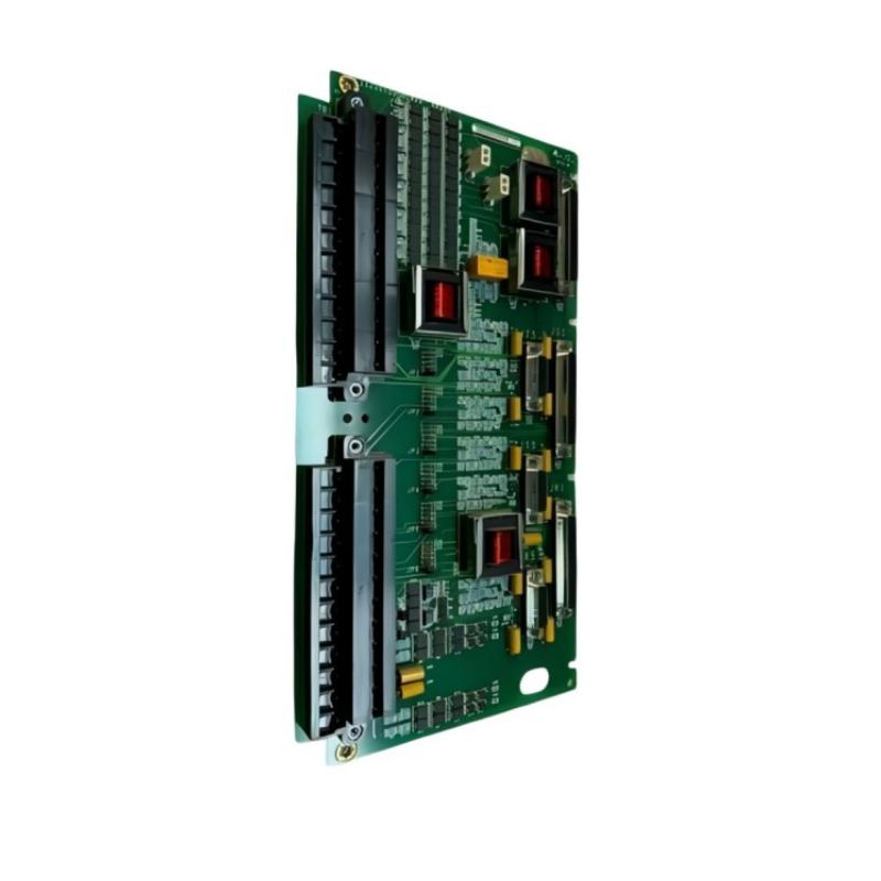
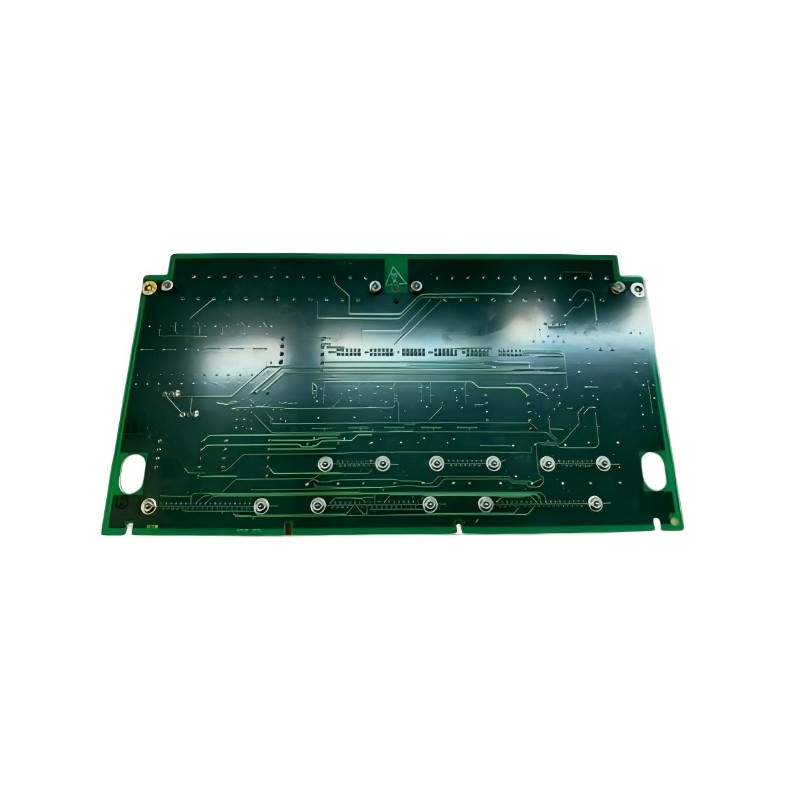
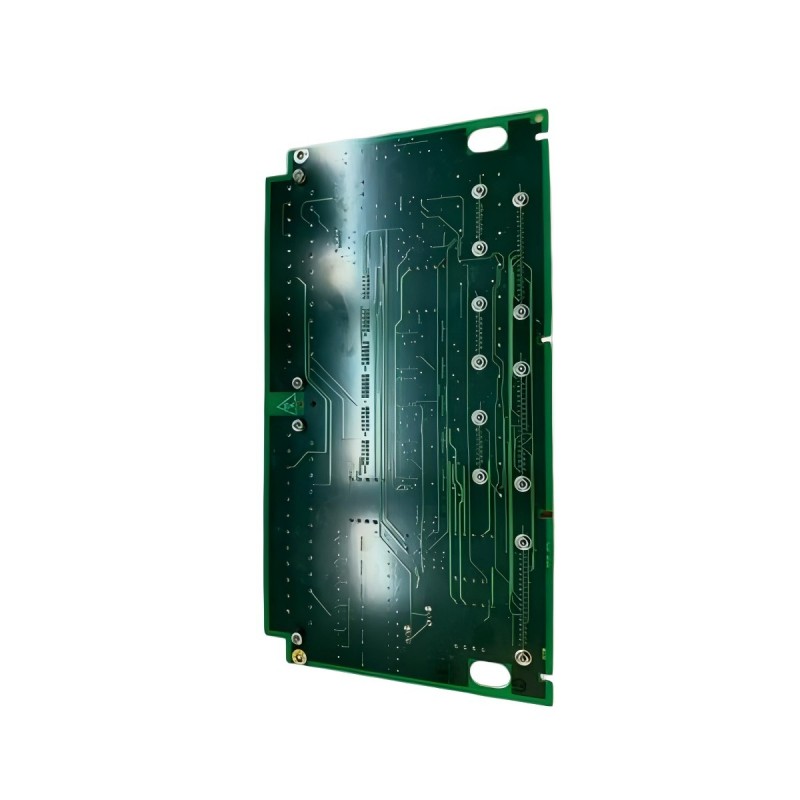
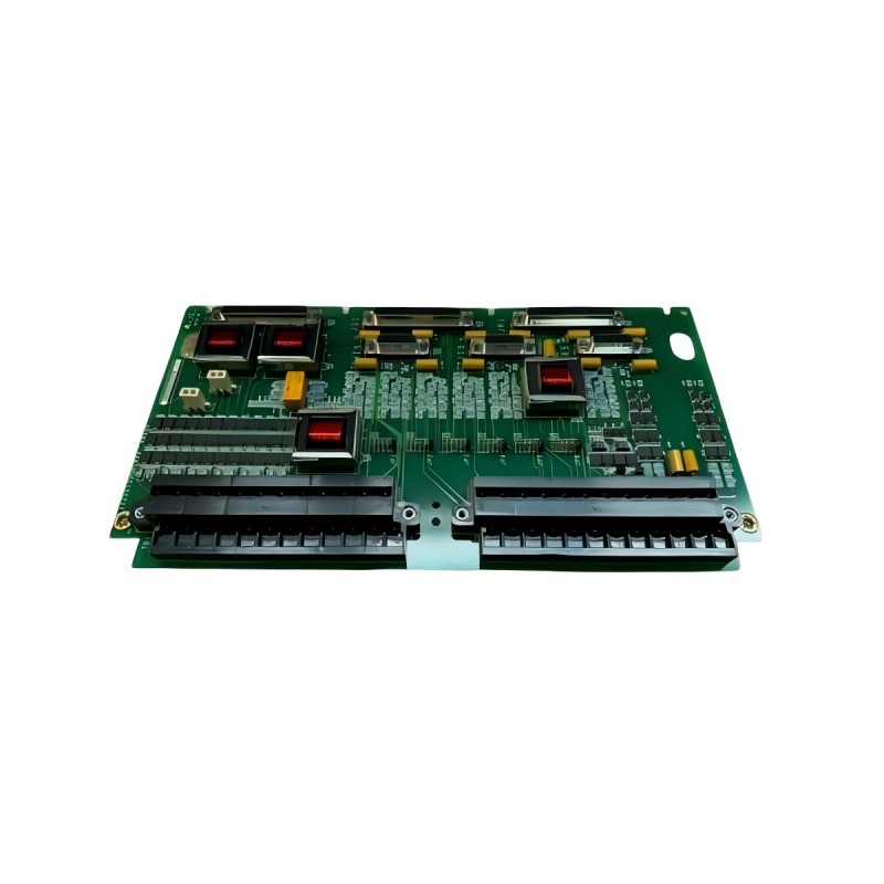
- GE
- IS220TTURH1C
- Terminal Block
- USA
- 330 x 20 x 178 mm
- 0.4 kg
- Xiamen, China
- New & In Stock
- T/T, PayPal, Western Union
- 1 Year
- 1-3 Working Days
- DHL, UPS, TNT, FedEx and EMS.
- 24-Hour Service
- COO
- 45
Our advantage

Global Logistics
We have a 10-year logistics and express cooperation agreement, so our products can be shipped to any place in the world.

Brand new and original
Our products are imported in bulk from the place of origin. Because of the cooperative relationship, our products are all original and 100% new.

24-hour service
We provide 7*24 hours service to our customers. We will be there whenever you need us.

Price advantage
All our products are priced very favorably because we have our own warehouse and supply.
| Company Information | |||
| [email protected] | |||
| Mobile | +8615980777398 | ||
| +8615980777398 | |||
| 15980777398 |
Product Overview
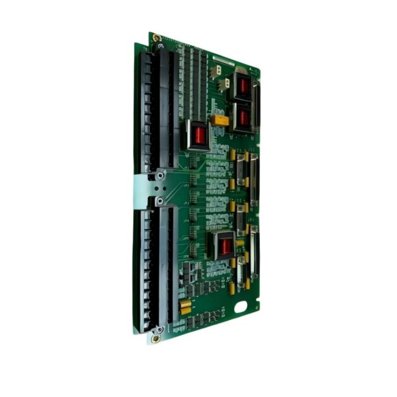
The GE IS220TTURH1C Terminal Block is an industrial interface component designed to provide an organized connection point between field wiring and compatible control-system equipment. In complex industrial automation environments, reliable field wiring is essential for transferring signals between sensors, actuators, terminal assemblies, and control electronics.
A terminal block helps simplify this connection architecture by providing a structured interface for field conductors. It can support easier installation, inspection, maintenance, troubleshooting, and replacement while helping keep cabinet wiring organized.
The GE IS220TTURH1C is associated with GE industrial control equipment and can be incorporated into an automation architecture where field connections need to be routed between external devices and the corresponding control-system hardware.
The listed dimensions of the GE IS220TTURH1C are 330 × 20 × 178 mm, with a listed weight of approximately 0.4 kg. Its physical size should be considered when planning cabinet space, wiring routes, connector access, and maintenance clearance.
Because terminal configurations can vary according to hardware revision and system architecture, exact terminal assignments, electrical ratings, supported signal types, channel configuration, and wiring functions should be verified against the applicable system documentation before installation.
Technical Specifications
| Parameter | Specification |
|---|---|
| Manufacturer | General Electric (GE) |
| Model | IS220TTURH1C |
| Product Type | Terminal Block |
| Product Family | GE IS220 Series |
| Primary Function | Field wiring and control-system connection interface |
| Application | Industrial automation and process control |
| Dimensions | 330 × 20 × 178 mm |
| Weight | 0.4 kg |
| Installation | Compatible GE industrial control equipment |
| System Role | Field wiring interface |
| Typical Application | Industrial control, instrumentation, field signal connection, and equipment integration |
The exact terminal numbering, electrical ratings, signal assignments, connector arrangement, and compatible field devices should be confirmed for the specific IS220TTURH1C installation.
What Is the GE IS220TTURH1C?
The GE IS220TTURH1C is a Terminal Block used as part of an industrial control-system connection architecture.
In a typical automation cabinet, numerous field cables must be connected to control equipment. Without an organized termination structure, large numbers of conductors can become difficult to identify and maintain.
A terminal block provides a defined physical interface for these connections.
A simplified architecture can be represented as:
Field Equipment → Field Wiring → IS220TTURH1C → Control-System Interface → Controller
The exact signal path depends on the host equipment and system design.
Function of a Terminal Block
The primary purpose of a terminal block is to provide a structured connection point for electrical conductors.
In an industrial automation system, the terminal interface can help with:
- Field wiring organization
- Signal termination
- Cable identification
- Maintenance access
- Wiring inspection
- Troubleshooting
- System commissioning
- Equipment replacement
The terminal block does not replace the controller or the I/O electronics. Instead, it forms part of the physical connection layer between field devices and control-system components.
Role in Industrial Control Systems
Industrial control systems typically contain several layers:
Process → Field Devices → Wiring → Terminal Interface → I/O System → Controller → HMI/SCADA
The terminal block occupies an important position between field wiring and electronic control equipment.
Sensors, switches, transmitters, actuators, and other field devices may be installed at considerable distances from the control cabinet. Their cables must eventually enter the cabinet and connect to the appropriate control-system interfaces.
A structured terminal arrangement helps engineers and technicians identify these connections more efficiently.
Field Wiring Organization
A well-organized terminal interface can significantly improve cabinet maintenance.
Each field cable should be identified according to the approved electrical drawings and system documentation.
Typical identification practices include:
- Cable numbers
- Terminal numbers
- Device tags
- Signal descriptions
- Cabinet references
- Equipment identifiers
Clear labeling reduces the risk of incorrect connections during commissioning or maintenance.
For the IS220TTURH1C, technicians should use the actual terminal identification and wiring documentation associated with the installed system rather than assuming a generic terminal arrangement.
Connection Between Field Devices and Control Equipment
Industrial field devices can include:
- Temperature sensors
- Pressure transmitters
- Flow instruments
- Level instruments
- Limit switches
- Solenoid valves
- Actuators
- Equipment status contacts
- Turbine-related instrumentation
- Protection devices
The terminal interface provides a structured point through which field wiring can be connected to the appropriate control-system interface.
The exact field-device compatibility depends on the host system.
Industrial Automation Applications
Process Control
Terminal blocks are commonly used in process-control cabinets where numerous field instruments must be connected to control electronics.
Turbine Control
Industrial turbine systems contain many sensors, control devices, status signals, and protection circuits. Organized field wiring is particularly important in these applications.
Power Generation
Power-generation facilities use extensive instrumentation and control wiring. Structured terminal interfaces help simplify cabinet installation and maintenance.
Industrial Instrumentation
Instrumentation systems often contain large numbers of field signals. Organized termination can make these signals easier to trace.
Manufacturing Automation
Production equipment may contain sensors, switches, actuators, and other electrical devices requiring organized cabinet wiring.
Equipment Modernization
Terminal interfaces can also be useful when integrating existing field wiring with replacement or upgraded control equipment.
Physical Characteristics
The GE IS220TTURH1C has listed dimensions of:
330 × 20 × 178 mm
The listed weight is:
0.4 kg
The relatively long physical dimension should be considered during cabinet planning.
Engineers should allow sufficient space for:
- Cable entry
- Wire bending
- Terminal access
- Connector access
- Identification labels
- Inspection
- Maintenance
- Adjacent equipment
The dimensions alone should not be interpreted as the required total installation clearance.
Cabinet Installation Planning
Before installing the terminal block, the cabinet layout should be reviewed.
Important considerations include:
Mounting Position
The terminal block should be installed in the designated location specified by the equipment documentation.
Wiring Access
There should be sufficient space for incoming and outgoing cables.
Cable Bend Radius
Field cables should be routed according to the requirements of the cable manufacturer and system design.
Identification
Terminal and cable labels should remain visible after installation.
Maintenance Clearance
Technicians should be able to inspect and service the connection points without unnecessary disassembly.
Installation Guidelines
Step 1: Confirm the Model
Verify the complete part number:
GE IS220TTURH1C
Check the installed equipment documentation before beginning replacement or installation work.
Step 2: Inspect the Terminal Block
Check for:
- Cracks
- Mechanical damage
- Bent connection points
- Contamination
- Loose components
- Signs of overheating
Step 3: Verify Field Wiring
Compare the field wiring against the approved electrical drawings.
Step 4: Confirm Terminal Identification
Ensure that each conductor is connected to the correct terminal position.
Step 5: Secure Connections
All connections should be mechanically secure and installed according to the applicable system requirements.
Step 6: Inspect Cable Routing
Make sure cables are properly routed and do not interfere with moving or high-temperature equipment.
Wiring and Signal Integrity
Although a terminal block is primarily a physical connection interface, connection quality can have a significant effect on overall system reliability.
Poor connections can produce:
- Intermittent signals
- Increased electrical resistance
- Unstable measurements
- False alarms
- Communication problems
- Unexpected equipment behavior
For this reason, wiring should be installed carefully and inspected during commissioning.
Signal cables should also be routed appropriately relative to high-power conductors and other potential sources of electrical interference.
Grounding and Shielding Considerations
Some industrial signal circuits require specific grounding or shielding arrangements.
The correct grounding strategy depends on the host system, field devices, signal type, and applicable electrical design.
Technicians should not assume that every terminal connection should be grounded in the same manner.
Where shielded instrumentation cables are used, the shield termination method should follow the approved system design.
Incorrect grounding can contribute to:
- Electrical noise
- Ground loops
- Measurement instability
- Unwanted signal interference
Commissioning Procedure
A structured commissioning process can help verify the terminal interface.
Visual Inspection
Confirm that the terminal block and surrounding wiring are correctly installed.
Wiring Verification
Check each connection against the electrical drawings.
Continuity Verification
Where appropriate and safe, verify continuity through the intended wiring path.
Signal Verification
Confirm that field signals reach the correct control-system interface.
Controller Verification
Check that the control system identifies the expected field signals.
Functional Testing
Operate the relevant field device or process equipment and confirm that the control system responds correctly.
Troubleshooting the GE IS220TTURH1C
Terminal-related faults should be investigated as part of the complete field-to-controller signal path.
A practical troubleshooting sequence is:
Field Device → Cable → IS220TTURH1C → I/O Interface → Controller
No Signal at the Controller
Possible causes include:
- Disconnected field wiring
- Incorrect terminal connection
- Damaged cable
- Loose connection
- Field-device failure
- Incorrect I/O configuration
- Upstream interface problem
The terminal block should not automatically be identified as the source of the fault.
Intermittent Signal
An intermittent signal may indicate:
- Loose connection
- Cable damage
- Vibration
- Connector problems
- Moisture
- Mechanical stress
- Electrical interference
Physical inspection should be combined with signal monitoring.
Incorrect Signal
If the controller receives an unexpected signal, check:
- Terminal assignment
- Cable identification
- Field-device configuration
- Signal wiring
- I/O configuration
- Grounding
- Shielding
Multiple Signal Failures
If several signals fail simultaneously, investigate common points such as:
- Shared wiring
- Common terminal interfaces
- Power supply
- I/O hardware
- Common grounding
- Controller configuration
A single field-device failure is less likely to explain multiple unrelated signal losses.
Preventive Maintenance
Regular inspection can help reduce connection-related failures.
Inspect Terminal Connections
Check for loose, damaged, or contaminated connections.
Check Cable Condition
Inspect cables for:
- Cuts
- Abrasion
- Cracked insulation
- Excessive bending
- Moisture
- Mechanical damage
Inspect Labels
Terminal and cable identification should remain readable.
Check for Heat Damage
Discoloration or deformation may indicate excessive temperature or a poor electrical connection.
Review Fault History
Repeated signal faults may indicate an underlying wiring or connection problem.
Replacement Considerations
When replacing the GE IS220TTURH1C, technicians should verify:
- Complete model number
- Hardware revision
- Existing installation position
- Terminal configuration
- Connector arrangement
- Field wiring
- Associated I/O equipment
- Host control system
- Electrical documentation
The complete model designation should be checked before removing the existing component.
A terminal block with a similar appearance should not automatically be considered interchangeable.
Physical dimensions alone are insufficient to establish electrical compatibility.
Maintenance and Fault Isolation Strategy
When troubleshooting a field signal, technicians can divide the system into several sections:
Section 1: Field Device
Check whether the sensor, switch, transmitter, actuator, or other device is functioning.
Section 2: Field Cable
Check continuity, insulation condition, mechanical damage, and routing.
Section 3: Terminal Interface
Check the IS220TTURH1C connections and physical condition.
Section 4: I/O Interface
Check the associated electronic I/O equipment.
Section 5: Controller
Verify configuration, logic, diagnostics, and signal processing.
This structured approach reduces unnecessary component replacement.
System Integration
The IS220TTURH1C can be considered part of the physical wiring layer of a larger industrial automation architecture.
A simplified structure is:
Process Equipment
↓
Field Sensors / Actuators
↓
Field Cables
↓
IS220TTURH1C Terminal Interface
↓
I/O System
↓
Control Processor
↓
HMI / SCADA
Each layer performs a different function.
The terminal block provides the physical connection infrastructure required for reliable signal transfer between the field and control system.
Engineering Best Practices
Use Accurate Wiring Documentation
Always work from the latest approved electrical drawings.
Maintain Consistent Cable Labels
Consistent labeling makes future troubleshooting substantially easier.
Separate Signal and Power Wiring
Where required, maintain appropriate separation between instrumentation wiring and high-power conductors.
Inspect Connections During Maintenance
Connection quality should be included in routine cabinet inspections.
Record Replacement Information
When replacing a terminal component, record the exact model and revision where applicable.
Avoid Unverified Substitution
A visually similar component should not be installed without confirming its electrical and mechanical compatibility.
Key Advantages
Organized Field Connections
The terminal block provides a structured interface for industrial field wiring.
Simplified Maintenance
Clearly organized connections can make inspection and troubleshooting more efficient.
Compact Physical Design
The listed 330 × 20 × 178 mm dimensions provide a defined footprint for cabinet planning.
Lightweight Construction
The listed weight of 0.4 kg makes the component relatively easy to handle during installation and replacement.
Industrial Control Integration
The IS220TTURH1C can form part of a larger GE industrial automation and instrumentation architecture.
Improved Wiring Management
A structured terminal interface helps organize multiple field connections within an industrial control cabinet.
Technical FAQs
What is the GE IS220TTURH1C?
The GE IS220TTURH1C is a Terminal Block intended to provide a structured field-wiring interface within compatible GE industrial control equipment.
What is the primary function of a terminal block?
Its primary function is to provide organized electrical connection points between field wiring and associated control-system equipment.
What are the dimensions of the IS220TTURH1C?
The listed dimensions are 330 × 20 × 178 mm.
How much does the IS220TTURH1C weigh?
The listed weight is approximately 0.4 kg.
Where can the IS220TTURH1C be used?
It can be incorporated into compatible industrial automation, instrumentation, process-control, and turbine-control architectures where structured field wiring is required.
Can a similar GE terminal block replace the IS220TTURH1C?
A different terminal block should not be assumed to be interchangeable. The complete model number, revision, terminal configuration, electrical requirements, and host-system compatibility should be verified.
What can cause an intermittent signal?
Loose terminals, damaged cables, vibration, moisture, poor connections, electrical interference, and field-device problems can all contribute to intermittent signals.
Does the terminal block process control signals?
A terminal block primarily provides a physical connection interface. Signal processing is normally performed by associated I/O and control electronics.
How should the IS220TTURH1C be maintained?
Maintenance should include inspection of terminal connections, field wiring, cable identification, physical condition, grounding, shielding, and associated I/O equipment.
Conclusion
The GE IS220TTURH1C Terminal Block is an industrial connection component designed to provide an organized interface between field wiring and compatible control-system equipment. In complex automation environments, reliable field termination is essential for maintaining accurate signal transmission and simplifying commissioning, troubleshooting, and maintenance.
With listed dimensions of 330 × 20 × 178 mm and a weight of 0.4 kg, the IS220TTURH1C has a defined physical footprint that should be considered during control-cabinet planning and equipment replacement.
The terminal block itself should always be evaluated as part of the complete signal path. Field devices, cables, terminal connections, I/O electronics, controller configuration, grounding, and signal integrity can all influence system performance.
For installation or replacement work, technicians should verify the complete GE IS220TTURH1C identification and compare the terminal configuration with the applicable system documentation. Exact terminal assignments, electrical ratings, signal functions, and compatibility should be confirmed before commissioning to ensure reliable operation within the intended GE industrial automation system.