

ProductPRODUCT
Featured products



Contact Us
- GE
- IS220PTURH1AD
- Turbine I/O Module
- USA
- 120 x 80 x 40 mm
- 0.5 kg
- Xiamen, China
- New & In Stock
- T/T, PayPal, Western Union
- 1 Year
- 1-3 Working Days
- DHL, UPS, TNT, FedEx and EMS.
- 24-Hour Service
- COO
- 36
Our advantage

Global Logistics
We have a 10-year logistics and express cooperation agreement, so our products can be shipped to any place in the world.

Brand new and original
Our products are imported in bulk from the place of origin. Because of the cooperative relationship, our products are all original and 100% new.

24-hour service
We provide 7*24 hours service to our customers. We will be there whenever you need us.

Price advantage
All our products are priced very favorably because we have our own warehouse and supply.
| Company Information | |||
| [email protected] | |||
| Mobile | +8615980777398 | ||
| +8615980777398 | |||
| 15980777398 |
Product Overview
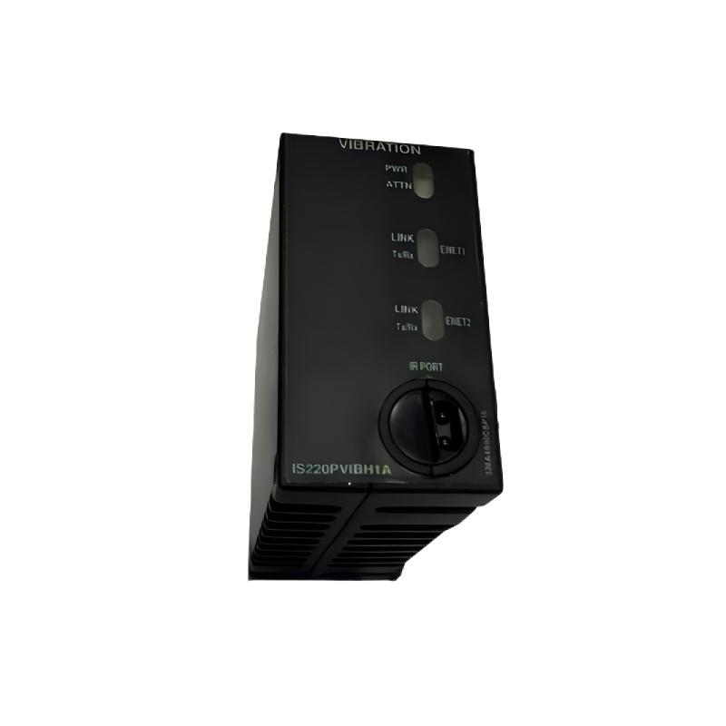
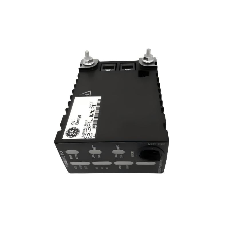
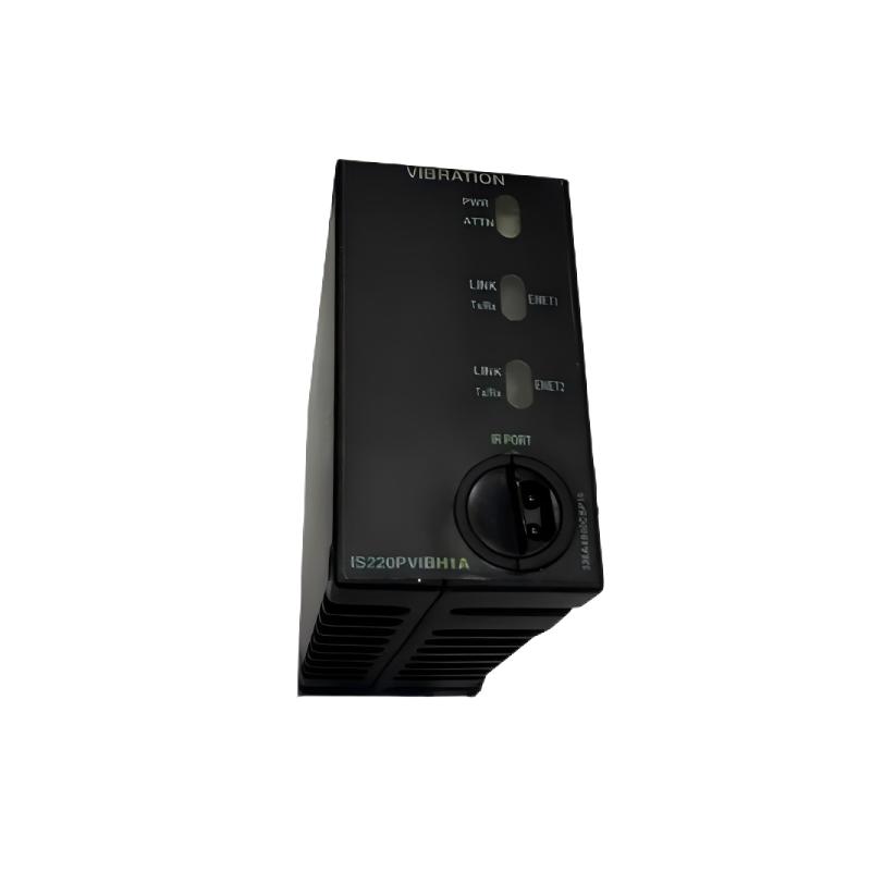
The GE IS220PTURH1AD Turbine I/O Module is a specialized industrial automation component designed to provide an interface between turbine field signals and a compatible GE control system. In turbine automation, reliable acquisition and processing of field information are essential for monitoring operating conditions, coordinating control functions, managing alarms, and supporting equipment protection.
A turbine I/O module forms an important connection point between physical equipment and digital control logic. Signals generated by sensors, switches, actuators, and other field devices must be transferred into the control architecture in a reliable and organized manner. The IS220PTURH1AD can serve as part of this interface layer within a suitable GE turbine automation system.
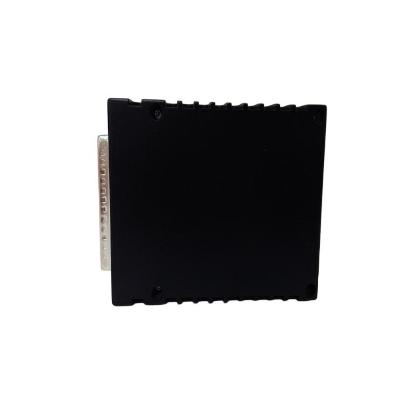
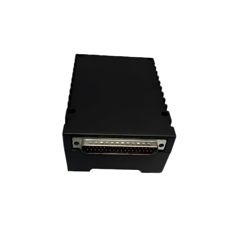
The listed dimensions of the GE IS220PTURH1AD are 120 × 80 × 40 mm, and the listed weight is approximately 0.5 kg. Its compact form factor allows it to be integrated into industrial control cabinets where multiple I/O, controller, communication, and protection components must be installed within a structured automation architecture.
The exact I/O channel configuration, signal types, electrical ratings, terminal assignments, isolation characteristics, communication functions, and diagnostic capabilities should be confirmed against the applicable hardware revision and host-system configuration before installation or replacement.
Technical Specifications
| Parameter | Specification |
|---|---|
| Manufacturer | General Electric (GE) |
| Model | IS220PTURH1AD |
| Product Type | Turbine I/O Module |
| Product Family | GE IS220 Series |
| Primary Function | Turbine field signal interface |
| Application | Turbine control, monitoring, and automation |
| Dimensions | 120 × 80 × 40 mm |
| Weight | 0.5 kg |
| Installation | Compatible GE industrial control equipment |
| System Role | Turbine I/O interface |
| Typical Application | Gas turbines, steam turbines, and industrial turbine systems |
The exact input/output channels, signal ranges, electrical characteristics, terminal configuration, communication interfaces, isolation, and protection functions should be verified for the specific IS220PTURH1AD installation.
What Is the GE IS220PTURH1AD?
The GE IS220PTURH1AD is a Turbine I/O Module intended to connect field-level turbine instrumentation and equipment with the associated control system.
Industrial turbines contain a large number of devices that provide information about equipment status and process conditions. These may include sensors, switches, valves, actuators, auxiliary equipment, and protection-related devices.
The I/O layer provides the electrical interface through which these field signals enter or leave the control system.
A simplified architecture is:
Turbine Equipment → Sensors / Field Devices → IS220PTURH1AD → Control System → HMI / SCADA
Depending on the system configuration, the module may participate in signal acquisition, equipment control, monitoring, alarm processing, and other turbine automation functions.
Role of a Turbine I/O Module
Turbine control systems require continuous information about the physical condition of the equipment.
Examples of monitored conditions can include:
- Equipment status
- Valve position
- Pressure
- Temperature
- Speed-related information
- Auxiliary system status
- Interlock conditions
- Alarm states
- Process conditions
- Control commands
The I/O module provides the interface between these field-level signals and the digital control architecture.
A reliable I/O interface is important because the controller can only make appropriate control decisions when the underlying field information is available and correctly interpreted.
Turbine Signal Architecture
A typical turbine automation system can be represented as:
Field Instrumentation → I/O Interface → Control Logic → Operator Interface
The field layer contains sensors and devices connected directly to the turbine or its auxiliary systems.
The I/O layer interfaces these physical signals with the control system.
The controller processes the signals according to the configured control logic.
The HMI or SCADA system provides operators with information about the equipment and process.
The IS220PTURH1AD can form part of the I/O layer in this overall architecture.
Field Signal Acquisition
Field devices continuously provide information about the operating condition of turbine equipment.
Depending on the application, these signals may represent:
- Equipment running status
- Valve states
- Pressure conditions
- Temperature conditions
- Auxiliary equipment status
- Interlocks
- Permissive conditions
- Alarm states
The I/O module receives the appropriate signals and transfers usable information into the control architecture.
Signal quality depends on more than the module itself. Field wiring, connectors, sensors, electrical noise, grounding, and configuration can all influence the final measurement or status received by the controller.
Turbine Control Applications
A turbine I/O architecture can support several major control functions.
Monitoring
The control system can monitor field signals continuously to determine the current state of turbine equipment.
Alarm Management
Abnormal field conditions can be transferred to the control system and used to generate operator alarms.
Interlocking
Field status signals can be incorporated into interlock and permissive logic.
Equipment Control
Where appropriate, output signals can be used to control valves, auxiliary equipment, or other devices.
Protection Support
Certain field signals may participate in protection or shutdown strategies depending on the overall turbine architecture.
The actual functions assigned to the IS220PTURH1AD depend on the specific application and control-system configuration.
Industrial Applications
Gas Turbine Systems
Gas turbines require extensive monitoring and control of mechanical, thermal, fuel, lubrication, and auxiliary systems.
Turbine I/O modules can provide the field interface required to integrate these signals into the control architecture.
Steam Turbines
Steam turbine installations use numerous field instruments and status devices to monitor operating conditions and coordinate equipment.
An I/O module can form part of the signal interface between these devices and the control system.
Power Generation
Power-generation facilities depend on reliable turbine control and monitoring to maintain stable plant operation.
The I/O architecture connects field equipment with controllers and operator systems.
Industrial Turbine Drives
Turbines can also be used in industrial plants to drive compressors, pumps, generators, and other equipment.
The associated I/O system can provide the control and monitoring interface required by these applications.
Utility and Process Systems
Industrial facilities often integrate turbine equipment with broader plant automation systems. I/O modules allow turbine signals to become part of centralized control and monitoring strategies.
Installation Guidelines
The IS220PTURH1AD should be installed by qualified personnel familiar with the associated GE turbine control system.
Verify the Hardware
Confirm the complete model number:
GE IS220PTURH1AD
The replacement component should be checked against the existing system documentation.
Inspect the Module
Before installation, inspect the module for:
- Physical damage
- Connector damage
- Contamination
- Mechanical deformation
- Signs of overheating
- Loose hardware
Confirm Cabinet Location
Verify that the module is installed in the correct cabinet and position according to the system design.
Check Connectors
Inspect connectors for:
- Bent contacts
- Contamination
- Loose engagement
- Cable strain
- Mechanical damage
Verify Field Wiring
Field wiring should be checked against approved drawings before the system is commissioned.
Wiring and Signal Integrity
Reliable turbine I/O operation depends heavily on field wiring quality.
Important considerations include:
Cable Routing
Signal cables should be routed appropriately and separated from high-power conductors where required.
Electrical Noise
Motors, drives, contactors, switching equipment, and other electrical loads can introduce interference into signal circuits.
Grounding
Appropriate grounding practices should be maintained according to the system design.
Connector Condition
Loose or contaminated connectors can cause intermittent signal problems.
Cable Condition
Damaged insulation, broken conductors, or moisture ingress can produce unstable or missing signals.
Commissioning Procedure
After installation, the IS220PTURH1AD should be commissioned systematically.
Step 1: Visual Inspection
Confirm that the module is properly installed and free from physical damage.
Step 2: Wiring Verification
Check field wiring and connectors against approved documentation.
Step 3: System Diagnostic Check
Review available controller and I/O diagnostics for hardware or communication faults.
Step 4: Field Signal Verification
Verify that expected field signals are correctly received by the control system.
Step 5: Output Verification
Where output functions are used, verify the corresponding equipment response according to approved commissioning procedures.
Step 6: Control Logic Verification
Confirm that the I/O signals are correctly associated with the intended control, alarm, or interlock functions.
Step 7: Operational Monitoring
Monitor the system during operation and check for abnormal diagnostics or intermittent signals.
Troubleshooting the GE IS220PTURH1AD
When an I/O fault occurs, technicians should troubleshoot the complete signal path rather than immediately replacing the module.
A useful diagnostic sequence is:
Field Device → Wiring → Connector → IS220PTURH1AD → Controller → Control Logic → HMI
No Input Signal
Possible causes include:
- Failed field device
- Broken cable
- Incorrect wiring
- Loose connector
- Module power problem
- Configuration error
- I/O hardware fault
The field device should be checked before concluding that the module has failed.
Incorrect Signal
An incorrect signal may result from:
- Sensor problems
- Wiring errors
- Incorrect configuration
- Electrical interference
- Field-device calibration issues
- Input-channel problems
Comparison with a known reference can help isolate the problem.
Intermittent Signal
Intermittent faults may be caused by:
- Loose terminals
- Damaged wiring
- Vibration
- Electrical noise
- Connector problems
- Temperature-related behavior
- Field-device instability
If several signals fail at the same time, common power, grounding, or communication problems should be considered.
Output Not Operating
If an expected output does not produce the intended equipment response, check:
- Control logic
- Output status
- Wiring
- Field device
- Power supply
- Interposing equipment
- Module diagnostics
The problem may exist outside the I/O module.
Diagnosing Multiple I/O Faults
When several channels become abnormal simultaneously, the diagnostic strategy should change.
Multiple failures can indicate a common problem such as:
- Module power
- Common wiring
- Communication
- Configuration
- Grounding
- Cabinet conditions
- Hardware failure
If only one channel is affected, the associated field device and wiring are usually important areas to inspect first.
This distinction helps maintenance personnel identify the fault more efficiently.
Preventive Maintenance
Regular maintenance can improve the reliability of turbine I/O systems.
Inspect Field Wiring
Check cables and terminals for:
- Damage
- Loose connections
- Corrosion
- Moisture
- Mechanical stress
Inspect Connectors
Ensure that connectors remain properly engaged and free from contamination.
Review Diagnostics
Periodic review of controller and I/O diagnostics can reveal intermittent problems before they become major faults.
Monitor Field Signal Trends
Where applicable, monitoring trends can help identify abnormal equipment behavior.
Maintain Cabinet Conditions
Control cabinets should be protected from excessive:
- Heat
- Dust
- Moisture
- Vibration
- Electrical interference
Physical Dimensions and Cabinet Planning
The GE IS220PTURH1AD has listed dimensions of:
120 × 80 × 40 mm
The listed weight is:
0.5 kg
These physical characteristics should be considered when planning:
- Control cabinet layout
- Replacement access
- Cable routing
- Module spacing
- Maintenance clearance
- Spare-parts storage
The stated dimensions represent the listed package size and should not be treated as the complete installation clearance requirement.
Integration with HMI and SCADA
Turbine I/O signals are often integrated into operator and supervisory systems.
A simplified architecture is:
Field Equipment → IS220PTURH1AD → Controller → HMI / SCADA
The operator interface may display:
- Equipment status
- Process conditions
- Alarm information
- Interlock states
- Diagnostic conditions
- Control-system status
This integration gives operators a centralized view of turbine operation.
The exact data displayed depends on the controller configuration and application software.
Turbine Protection and Interlocks
Turbine control systems frequently use field signals as part of interlocks and permissive logic.
For example, equipment status information may be used to determine whether a particular operating sequence is permitted.
Temperature, pressure, valve-position, auxiliary-equipment, and other status signals can also contribute to alarm or protection strategies.
The IS220PTURH1AD should therefore be viewed as part of a larger control and protection architecture rather than as an independent protection device.
The exact safety and protection functions depend on the engineered turbine system.
Replacement Considerations
When replacing the GE IS220PTURH1AD, verify the complete hardware identification before installation.
Important information includes:
- Full model number
- Revision designation
- Cabinet location
- Connector arrangement
- Field wiring
- Associated controller
- I/O configuration
- Application software
A different GE I/O module should not be assumed to be directly interchangeable merely because it has similar dimensions.
Functional and electrical compatibility should always be confirmed before installation.
Engineering Best Practices
Reliable turbine I/O operation depends on proper engineering and maintenance practices.
Maintain Accurate Documentation
Keep wiring diagrams, cabinet drawings, I/O assignments, and configuration information current.
Label Field Wiring
Clear identification of field cables can significantly reduce maintenance time.
Separate Signal and Power Wiring
Where appropriate, maintain physical separation between sensitive signal cables and high-power conductors.
Monitor Diagnostic Information
Repeated I/O faults or communication errors should be investigated rather than ignored.
Maintain Spare Hardware
A correctly identified spare module can reduce downtime during critical maintenance activities.
Verify Configuration After Replacement
After installing replacement hardware, confirm that the physical I/O arrangement corresponds with the control-system configuration.
Key Advantages
Dedicated Turbine I/O Interface
The IS220PTURH1AD provides a specialized interface for turbine-related field signals within a compatible GE automation architecture.
Compact Physical Design
With listed dimensions of 120 × 80 × 40 mm, the module can be incorporated into appropriately designed industrial control cabinets.
Lightweight Construction
The listed weight of 0.5 kg makes the module practical to handle during installation and maintenance.
Integration with Turbine Control
The module can connect field-level information with turbine control, monitoring, alarm, and interlock functions.
Suitable for Industrial Applications
Turbine I/O architecture can be applied across power-generation, industrial turbine, and process environments.
Supports Centralized Monitoring
Field information can be incorporated into controller, HMI, SCADA, and diagnostic systems.
Technical FAQs
What is the GE IS220PTURH1AD?
The GE IS220PTURH1AD is a Turbine I/O Module designed to interface turbine field signals with a compatible GE industrial control system.
What is the main function of the IS220PTURH1AD?
Its primary role is to provide an I/O interface between turbine field equipment and the associated control architecture.
What are the dimensions of the IS220PTURH1AD?
The listed dimensions are 120 × 80 × 40 mm.
How much does the IS220PTURH1AD weigh?
The listed weight is approximately 0.5 kg.
Where can the IS220PTURH1AD be used?
It can form part of compatible turbine control and monitoring systems used in power generation, industrial turbine installations, and process applications.
What can cause an I/O signal problem?
Possible causes include field-device failure, wiring problems, connector issues, electrical interference, configuration errors, power problems, communication faults, or module failure.
Can another GE I/O module replace the IS220PTURH1AD?
A different I/O module should not be assumed to be directly compatible. The complete model number, revision, I/O characteristics, wiring, and host-system configuration should be verified before replacement.
How should the IS220PTURH1AD be maintained?
Maintenance should include inspection of the module, connectors, field wiring, cabinet conditions, system diagnostics, and associated field devices.
Is the IS220PTURH1AD a standalone turbine controller?
No. It should be considered an I/O component within a larger turbine control and automation architecture. Its actual functions depend on the host system and configuration.
Conclusion
The GE IS220PTURH1AD Turbine I/O Module is a specialized industrial interface component designed to connect turbine field-level signals with a compatible GE control and automation architecture. By providing an interface between sensors, switches, equipment, and control logic, an I/O module forms an important part of the overall turbine monitoring and control system.
The IS220PTURH1AD has listed dimensions of 120 × 80 × 40 mm and a weight of 0.5 kg, providing a compact physical solution for industrial control cabinet installations.
Reliable turbine I/O performance depends on the complete signal chain. Field devices, wiring, connectors, grounding, electrical conditions, configuration, controller logic, and the I/O module itself can all influence system operation. A systematic diagnostic approach is therefore recommended whenever an I/O problem occurs.
For replacement and maintenance applications, the complete GE IS220PTURH1AD model designation should be verified carefully. Exact channel configuration, signal types, electrical ratings, terminal assignments, isolation characteristics, and system-specific functions should be confirmed against the applicable hardware revision and control-system documentation before installation and commissioning.