

ProductPRODUCT
Featured products



Contact Us
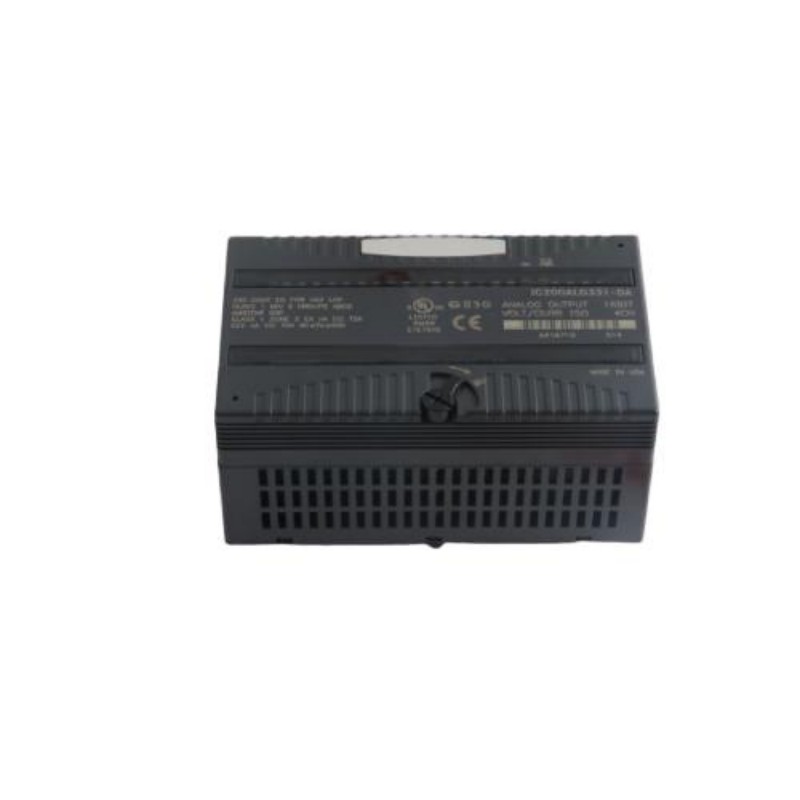
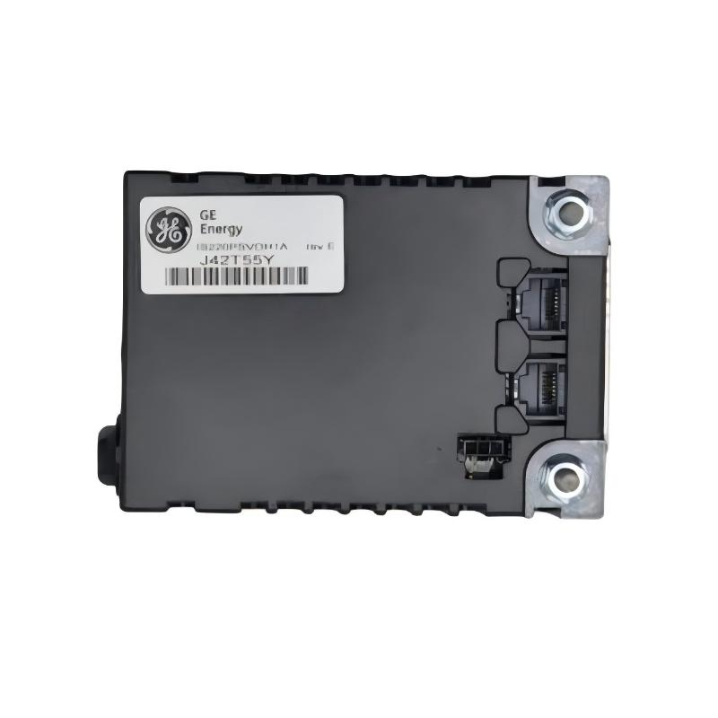
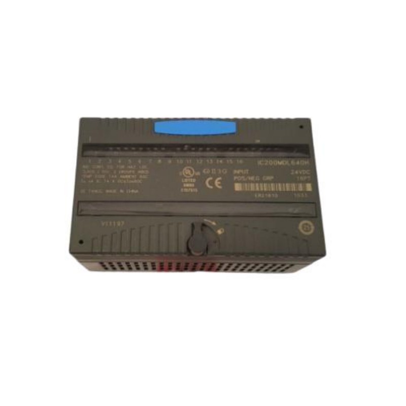
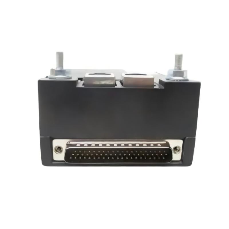
- GE
- IS220PRROH1A
- Backup Turbine Protection I/O Package
- USA
- 143 x 231 x 64 mm
- 0.45 kg
- Xiamen, China
- New & In Stock
- T/T, PayPal, Western Union
- 1 Year
- 1-3 Working Days
- DHL, UPS, TNT, FedEx and EMS.
- 24-Hour Service
- COO
- 32
Our advantage

Global Logistics
We have a 10-year logistics and express cooperation agreement, so our products can be shipped to any place in the world.

Brand new and original
Our products are imported in bulk from the place of origin. Because of the cooperative relationship, our products are all original and 100% new.

24-hour service
We provide 7*24 hours service to our customers. We will be there whenever you need us.

Price advantage
All our products are priced very favorably because we have our own warehouse and supply.
| Company Information | |||
| [email protected] | |||
| Mobile | +8615980777398 | ||
| +8615980777398 | |||
| 15980777398 |
Product Overview
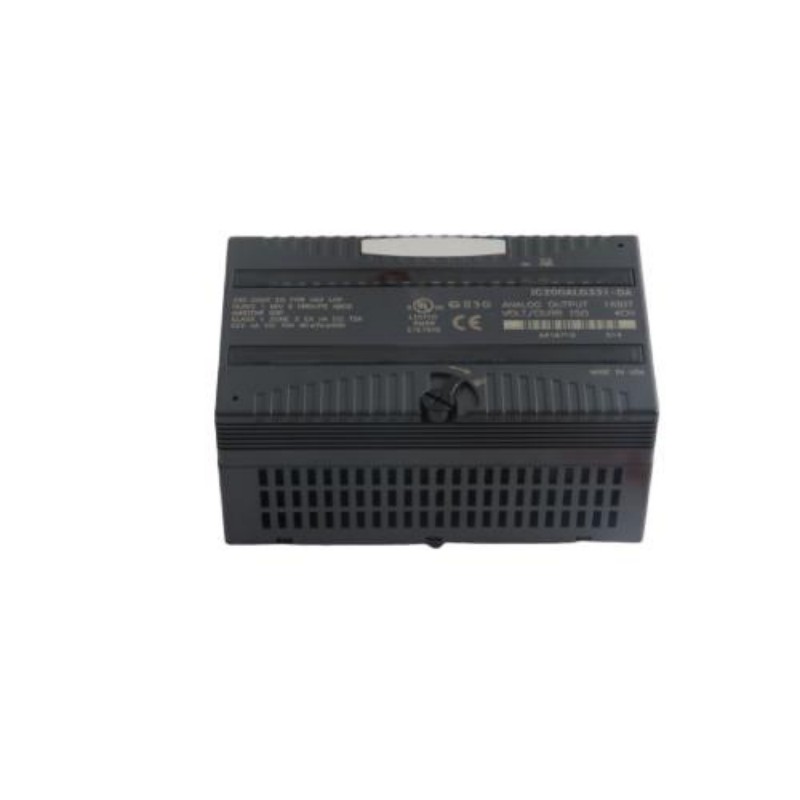
The GE IS220PRROH1A Backup Turbine Protection I/O Package is a specialized industrial control and protection component designed for turbine automation systems where dependable signal processing, protection logic, and continuous equipment monitoring are essential. As part of the GE Mark VIe family of industrial control hardware, the IS220PRROH1A is intended to participate in the interface between turbine field signals and the associated control and protection architecture.
Turbine protection systems must respond reliably to abnormal operating conditions while maintaining continuous communication with the supervisory control system. A backup protection I/O package provides an additional layer within this architecture, supporting the acquisition and handling of field information associated with turbine protection functions.
The GE IS220PRROH1A has listed dimensions of 143 × 231 × 64 mm and a weight of approximately 0.45 kg. Its compact package format allows it to be incorporated into industrial control cabinets where protection, monitoring, and I/O equipment must be installed alongside controllers, terminal assemblies, communication equipment, and other turbine automation hardware.
The exact electrical configuration, field I/O characteristics, terminal assignments, communication architecture, and protection functions should be verified against the applicable turbine system documentation and hardware revision before installation or replacement.
Technical Specifications
| Parameter | Specification |
|---|---|
| Manufacturer | General Electric (GE) |
| Model | IS220PRROH1A |
| Product Type | Backup Turbine Protection I/O Package |
| Product Family | GE Mark VIe |
| Primary Function | Backup turbine protection I/O interface |
| Application | Turbine control, protection, and monitoring |
| Dimensions | 143 × 231 × 64 mm |
| Weight | 0.45 kg |
| Installation | Industrial control cabinet / compatible turbine control system |
| System Role | Protection and field I/O interface |
| Typical Application | Gas turbines, steam turbines, and industrial turbine automation systems |
The exact number and type of supported I/O channels, signal levels, electrical ratings, isolation characteristics, terminal configuration, communication interfaces, and diagnostic functions should be confirmed for the specific IS220PRROH1A hardware revision and host-system configuration.
What Is the GE IS220PRROH1A?
The IS220PRROH1A is a Backup Turbine Protection I/O Package intended for use within a GE turbine control and protection environment.
Turbine protection systems are responsible for detecting operating conditions that could threaten turbine equipment, generators, auxiliary systems, or personnel. Depending on the system architecture, protection-related signals may include process measurements, equipment status signals, trip conditions, permissive signals, alarm states, and other field information.
The IS220PRROH1A can be understood as part of the signal interface layer connecting turbine field instrumentation with the control and protection architecture.
A simplified system arrangement can be represented as:
Turbine Equipment → Field Sensors / Switches → I/O Package → Protection and Control Logic → Turbine Response
In a backup protection architecture, the objective is to provide an additional path for monitoring and protection-related functions so that important turbine conditions can remain supervised when required by the system design.
Backup Turbine Protection Function
Turbine protection differs from ordinary process monitoring because protection functions must respond appropriately to abnormal conditions.
A turbine may operate at high rotational speed, temperature, pressure, and mechanical load. Abnormal conditions can develop rapidly, making reliable signal acquisition and protection logic essential.
A backup turbine protection I/O package can form part of the architecture responsible for handling signals associated with conditions such as:
- Turbine operating status
- Overspeed-related protection
- Trip and permissive conditions
- Equipment fault indications
- Process protection signals
- Auxiliary equipment status
- Alarm conditions
- Interlock signals
- Emergency shutdown-related information
The exact protection functions implemented by the complete turbine system depend on the turbine configuration, control philosophy, application software, field instrumentation, and system design.
The IS220PRROH1A should therefore be considered as one component of a larger protection architecture rather than as an independent protection controller.
Role in Turbine Control Architecture
Modern turbine automation systems generally divide control responsibilities among several functional layers.
A simplified architecture may include:
Field Devices → I/O Interface → Controller / Protection Logic → Communication Network → HMI / SCADA
The IS220PRROH1A operates within the I/O and protection interface portion of this architecture.
Its role may include receiving field information, interfacing with turbine protection-related signals, communicating status information to the associated control architecture, and supporting system-level diagnostics.
The separation between field signal acquisition and higher-level control logic is important because it allows turbine engineers to organize the protection system into clearly defined functional layers.
This architecture can also simplify troubleshooting because technicians can determine whether a problem originates from:
- The field device
- Field wiring
- The I/O interface
- The controller or protection logic
- The communication path
- The operator or supervisory system
Field Signal Interface
A turbine protection system depends on accurate information from field devices.
Typical field devices may include:
- Pressure switches
- Temperature sensors
- Speed sensing equipment
- Vibration monitoring devices
- Valve position feedback
- Generator status signals
- Lubrication system signals
- Fuel system signals
- Hydraulic system status
- Auxiliary equipment interlocks
- Emergency shutdown devices
The I/O package provides an electronic interface between the field layer and the turbine control system.
For protection applications, signal integrity is particularly important. A false signal may produce an unnecessary protective action, while a missing or incorrect signal could prevent the system from responding appropriately to an abnormal condition.
For this reason, field wiring, grounding, shielding, terminal connections, and module condition should all be considered when diagnosing protection-system problems.
Importance of Backup Protection
A turbine control system may contain multiple levels of monitoring and protection.
Primary control functions manage normal operation, while dedicated protection functions are intended to respond to abnormal conditions. Backup protection can provide additional system-level resilience depending on the engineering architecture.
The purpose of backup protection is not simply to duplicate every normal control function. Instead, the backup architecture can provide an additional means of monitoring or acting upon critical conditions defined by the turbine protection philosophy.
This makes the reliability of the associated I/O hardware important.
The IS220PRROH1A can therefore contribute to a protection architecture in which critical turbine conditions are monitored through dedicated signal paths.
Industrial Applications
The GE IS220PRROH1A is associated with industrial turbine automation and protection applications.
Potential application environments include:
Gas Turbine Systems
Gas turbines require coordinated monitoring of speed, temperature, pressure, fuel systems, lubrication, combustion-related conditions, and auxiliary equipment.
Protection I/O equipment can form part of the control and shutdown architecture used to supervise these operating conditions.
Steam Turbine Systems
Steam turbines depend on reliable monitoring of steam conditions, mechanical status, speed, valves, lubrication systems, and other auxiliary equipment.
Protection-related I/O interfaces can provide field information to the associated control and protection system.
Power Generation
In electrical power-generation facilities, turbine protection is closely integrated with generator and plant control systems.
A reliable I/O architecture allows important equipment conditions to be transferred to control and protection logic.
Industrial Cogeneration
Cogeneration plants use turbines as part of combined electrical and thermal energy systems. Continuous monitoring and protection are essential for maintaining reliable operation.
Process Industry Turbines
Industrial facilities may use turbines for mechanical drive, power generation, compression, or other process functions. Protection I/O hardware can support these specialized turbine applications.
Installation and System Integration
Installation should be performed only by qualified personnel familiar with the associated GE turbine control system.
Before installing the IS220PRROH1A, technicians should verify the complete part number, revision, cabinet location, system configuration, connector arrangement, and associated field wiring.
1. Verify the Part Number
Confirm that the replacement device is specifically identified as:
GE IS220PRROH1A
Do not rely only on physical appearance because GE industrial control components can have similar mechanical characteristics while serving different electrical functions.
2. Inspect the Existing Installation
Before removal, record:
- Module identification
- Cabinet position
- Connector locations
- Cable routing
- Terminal assignments
- Associated I/O devices
- Controller relationships
- Diagnostic indications
Photographic records and wiring documentation can be useful during replacement work.
3. Isolate the Equipment
Follow the applicable turbine shutdown, electrical isolation, and lockout/tagout procedures before removing or installing hardware.
Protection-system equipment should never be serviced while unsafe turbine or electrical conditions are present.
4. Inspect Connectors
Check connectors for:
- Loose engagement
- Contamination
- Mechanical damage
- Bent contacts
- Corrosion
- Cable strain
A poor connection can create intermittent protection-system faults that may initially appear to be an electronic module failure.
5. Confirm System Configuration
After installation, the hardware should be checked against the control-system configuration to ensure that the physical module corresponds to the expected system architecture.
Wiring and Signal Integrity
Reliable wiring is essential for turbine protection systems.
Protection signals may be affected by electrical noise, grounding problems, damaged cables, loose terminals, or incorrect wiring.
Good installation practices include:
- Keep signal wiring organized.
- Separate sensitive signal cables from high-power conductors where required.
- Maintain appropriate shielding practices.
- Verify grounding arrangements.
- Avoid excessive mechanical stress on connectors.
- Check cable identification before reconnection.
- Confirm field wiring against approved documentation.
The exact wiring method should follow the turbine control-system design and applicable installation documentation.
Commissioning Procedure
Following installation, commissioning should be performed systematically.
Step 1: Visual Inspection
Inspect the installed IS220PRROH1A for physical damage, incorrect positioning, loose connectors, or abnormal installation conditions.
Step 2: Power-System Verification
Verify that the associated cabinet power and system conditions are within the requirements of the host equipment.
Step 3: Diagnostic Check
Review available system diagnostics for module status, communication status, field-signal faults, or other abnormal indications.
Step 4: Signal Verification
Confirm that relevant field signals are being received correctly by the control and protection architecture.
Step 5: Protection Logic Verification
Where permitted by the approved commissioning procedure, verify the associated protection and interlock logic using controlled test conditions.
Step 6: System Monitoring
Observe the turbine control system for abnormal indications after commissioning.
Protection testing should always follow the plant’s approved procedures and safety requirements.
Troubleshooting the GE IS220PRROH1A
Troubleshooting should begin at the system level rather than immediately replacing the I/O package.
A protection-related fault can originate from field equipment, wiring, power, configuration, communication, or the module itself.
No Valid Signal
Possible causes include:
- Field device failure
- Cable disconnection
- Incorrect terminal connection
- Connector problem
- Power-supply issue
- I/O package fault
- Configuration problem
- Communication fault
Start by determining whether the problem affects one signal or multiple signals.
Intermittent Signal
An intermittent signal may be caused by:
- Loose wiring
- Connector movement
- Cable damage
- Electrical interference
- Grounding problems
- Field-device instability
- Temperature-related equipment behavior
- Hardware degradation
If multiple signals become unstable simultaneously, inspect common power, grounding, and communication paths before replacing individual components.
Incorrect Protection Status
If the system indicates an unexpected protection state, compare the actual field condition with the control-system indication.
Check:
- Field device
- Wiring
- Terminal connections
- I/O package status
- Controller diagnostics
- Protection logic
- HMI indication
This approach helps prevent unnecessary module replacement.
Module Diagnostic Fault
If the control system reports an I/O package fault, inspect the module’s physical condition and associated connections.
Check whether the fault remains after verifying:
- Power
- Connectors
- Wiring
- Configuration
- Communication
- Environmental conditions
If the fault persists, the module may require replacement or further bench-level evaluation.
Preventive Maintenance
Preventive maintenance can help reduce unexpected turbine control-system interruptions.
Recommended activities include:
Visual Inspection
Check the module and surrounding cabinet for contamination, physical damage, excessive heat, moisture, or loose hardware.
Connector Inspection
Inspect connectors periodically during scheduled maintenance activities.
Cable Inspection
Look for:
- Damaged insulation
- Excessive bending
- Loose cable supports
- Mechanical abrasion
- Incorrect routing
Cabinet Environment
Maintain appropriate cabinet conditions according to the overall control-system requirements.
Excessive heat, dust, moisture, and vibration can negatively affect electronic equipment.
Diagnostic Trend Monitoring
System diagnostic information can be useful for identifying intermittent problems before they develop into more serious failures.
Physical Dimensions and Cabinet Planning
The GE IS220PRROH1A has listed dimensions of:
143 × 231 × 64 mm
Its listed weight is:
0.45 kg
These values should be considered when planning cabinet installation, replacement logistics, and maintenance access.
The physical space around the package should also allow sufficient room for:
- Connector access
- Cable routing
- Inspection
- Removal and replacement
- Air circulation where required
- Adjacent equipment clearance
Actual cabinet spacing requirements should be determined from the host-system installation design rather than from the package dimensions alone.
Replacement Considerations
When replacing a GE IS220PRROH1A, the exact identification of the existing hardware is critical.
Technicians should verify:
- Full model number
- Revision information
- Hardware identification
- Cabinet location
- Connector arrangement
- Associated field wiring
- System configuration
- Protection architecture
The replacement unit should not be selected solely according to dimensions.
Two components may have similar physical dimensions but completely different electrical or functional characteristics.
For critical turbine protection applications, replacement work should also include appropriate functional verification before the turbine is returned to normal service.
Integration with Turbine Monitoring Systems
The IS220PRROH1A can form part of a larger turbine monitoring architecture.
A typical information flow may be represented as:
Field Instrumentation → I/O Interface → Protection / Control Processing → Operator Interface
The operator interface may display:
- Equipment status
- Alarm conditions
- Protection indications
- Interlock states
- Diagnostic information
- Process measurements
This layered architecture allows operators and maintenance personnel to distinguish between normal process changes and hardware or instrumentation problems.
System-Level Fault Diagnosis
When diagnosing a turbine protection problem, technicians should avoid assuming that the I/O package is automatically the source of the fault.
A useful diagnostic sequence is:
Field Device → Wiring → Terminal / Connector → I/O Package → Controller → Protection Logic → HMI
This approach is particularly important when a protection alarm appears after maintenance work.
For example, if a single protection signal is missing, the field sensor and associated cable should be checked first. If several unrelated signals disappear simultaneously, common power, communication, or configuration issues become more relevant.
System-level troubleshooting reduces unnecessary hardware replacement and helps identify the actual source of the problem.
Engineering Considerations
The IS220PRROH1A should be treated as part of a complete turbine protection system rather than as an isolated electronic component.
Important engineering considerations include:
- Protection-system architecture
- Signal availability
- Field-device reliability
- Wiring integrity
- Controller configuration
- Redundancy requirements
- Diagnostic coverage
- Maintenance accessibility
- Environmental conditions
- Replacement procedures
- Functional testing
The exact protection philosophy is application-specific and should be established by the turbine system design.
Key Advantages
Dedicated Turbine Protection Interface
The IS220PRROH1A is designed for turbine protection-related I/O applications within a compatible GE control architecture.
Backup Protection Architecture
Its intended role supports system architectures where backup protection and additional monitoring paths are required.
Compact Industrial Package
With dimensions of 143 × 231 × 64 mm, the package can be incorporated into appropriately designed industrial control cabinets.
Lightweight Construction
The listed weight of 0.45 kg simplifies handling during maintenance and replacement activities.
Integration with Turbine Automation
The package can form part of a broader turbine control, monitoring, diagnostic, and protection architecture.
Suitable for Continuous Industrial Operation
When correctly installed and integrated, protection I/O hardware can support continuous supervision of critical turbine operating conditions.
Technical FAQs
What is the GE IS220PRROH1A?
The GE IS220PRROH1A is a Backup Turbine Protection I/O Package designed for integration into compatible GE turbine control and protection systems.
What is the primary purpose of the IS220PRROH1A?
Its primary role is to provide an I/O interface associated with backup turbine protection and monitoring functions within a larger industrial control architecture.
What are the dimensions of the IS220PRROH1A?
The listed dimensions are 143 × 231 × 64 mm.
How much does the IS220PRROH1A weigh?
The listed weight is approximately 0.45 kg.
Is the IS220PRROH1A a standalone turbine protection controller?
It should not be treated as a standalone protection system. Its function depends on the associated turbine control architecture, field instrumentation, configuration, and protection logic.
What can cause an IS220PRROH1A-related fault?
Possible causes include field-device problems, wiring faults, connector problems, power issues, configuration errors, communication problems, environmental conditions, or hardware failure.
Can another GE I/O package directly replace the IS220PRROH1A?
A different GE I/O package should not be assumed to be interchangeable. The complete model number, revision, system configuration, connector arrangement, and functional requirements should be verified before replacement.
How should the IS220PRROH1A be maintained?
Maintenance should include visual inspection, connector and wiring checks, cabinet-environment inspection, diagnostic monitoring, and appropriate functional testing according to the turbine maintenance procedure.
Where is the IS220PRROH1A typically used?
It is intended for compatible turbine control and protection environments, including industrial turbine and power-generation applications.
Conclusion
The GE IS220PRROH1A Backup Turbine Protection I/O Package is a specialized component for turbine protection and monitoring architectures. By providing an interface between field-level turbine signals and the associated protection and control system, it can contribute to the reliable supervision of critical turbine operating conditions.
With listed dimensions of 143 × 231 × 64 mm and a weight of 0.45 kg, the IS220PRROH1A offers a compact form factor suitable for integration into appropriately designed industrial control cabinets.
Reliable operation depends on more than the I/O package itself. Field instrumentation, wiring, connectors, system configuration, protection logic, communication paths, and cabinet conditions all influence the performance of the complete protection system.
For maintenance and replacement applications, the complete GE IS220PRROH1A identification should be verified carefully. Because turbine protection is a safety- and reliability-critical function, installation, commissioning, testing, and troubleshooting should be performed according to the applicable turbine control-system procedures and engineering requirements.