

ProductPRODUCT
Featured products



Contact Us
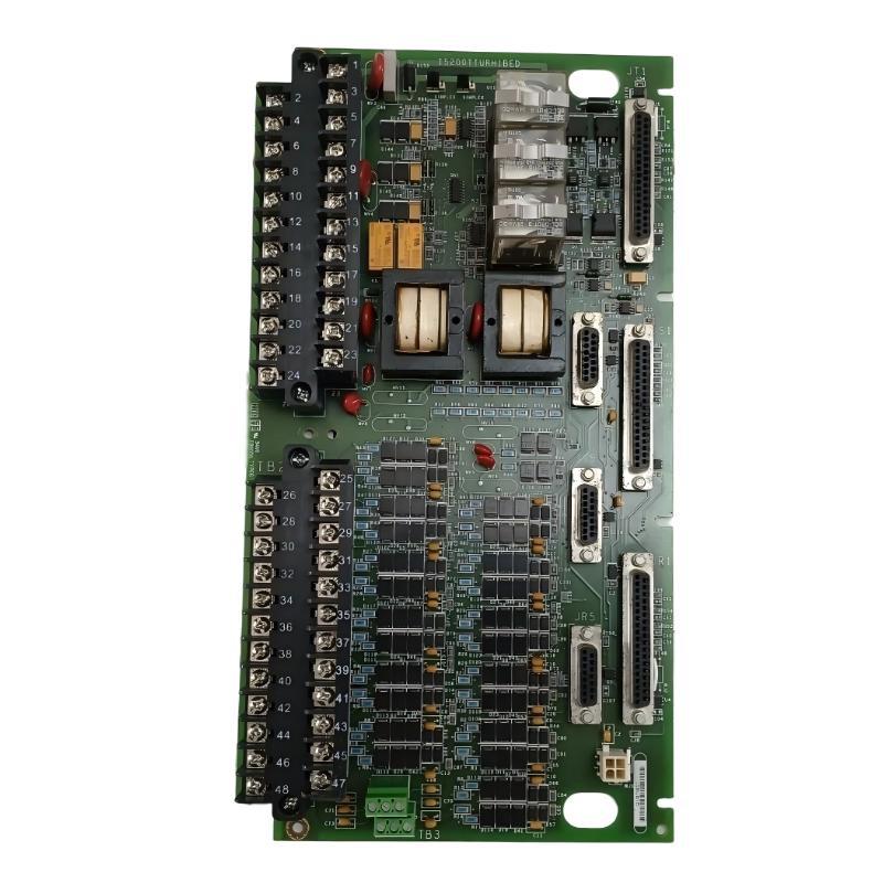
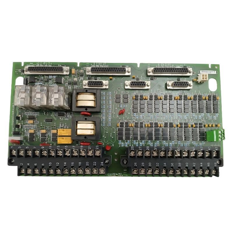
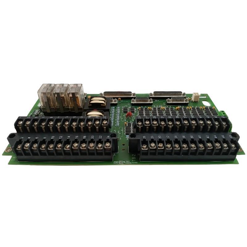
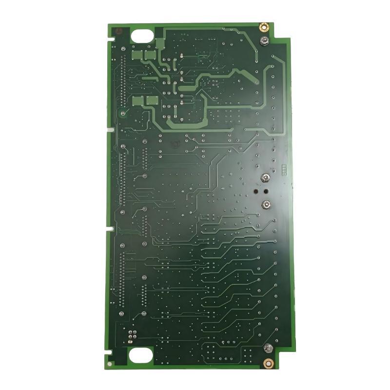
- GE
- IS200TTURH1BED
- Turbine Terminal Block
- USA
- 330 x 20 x 178 mm
- 0.66 kg
- Xiamen, China
- New & In Stock
- T/T, PayPal, Western Union
- 1 Year
- 1-3 Working Days
- DHL, UPS, TNT, FedEx and EMS.
- 24-Hour Service
- COO
- 26
Our advantage

Global Logistics
We have a 10-year logistics and express cooperation agreement, so our products can be shipped to any place in the world.

Brand new and original
Our products are imported in bulk from the place of origin. Because of the cooperative relationship, our products are all original and 100% new.

24-hour service
We provide 7*24 hours service to our customers. We will be there whenever you need us.

Price advantage
All our products are priced very favorably because we have our own warehouse and supply.
| Company Information | |||
| [email protected] | |||
| Mobile | +8615980777398 | ||
| +8615980777398 | |||
| 15980777398 |
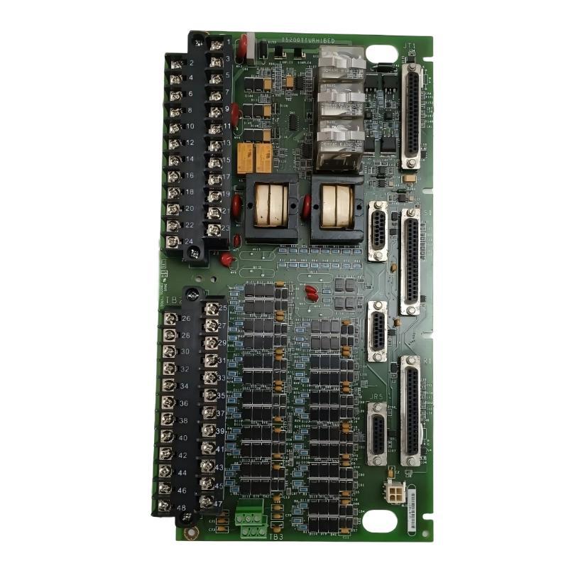
Product Overview
The GE IS200TTURH1BED Turbine Terminal Block is an industrial terminal and signal-interface assembly designed for integration into compatible GE turbine control systems. It provides an organized termination point for field wiring associated with turbine instrumentation, monitoring devices, control circuits, and other equipment connected to the turbine automation architecture.
In modern turbine control systems, numerous signals must travel between field devices and electronic control hardware. These signals may originate from sensors, switches, valve feedback devices, auxiliary equipment, and other turbine-related instrumentation. A properly configured terminal block provides a structured connection between these field circuits and the control-system I/O architecture.
The GE IS200TTURH1BED has listed dimensions of 330 × 20 × 178 mm and a weight of approximately 0.66 kg. Its long, compact form factor is suitable for installation within industrial control cabinets where multiple field connections need to be arranged in a clearly defined and serviceable manner.
Rather than functioning as an independent controller, the IS200TTURH1BED operates as part of a larger turbine automation system. Its effectiveness depends on the correct combination of field devices, wiring, I/O electronics, control processors, and system configuration.
Technical Specifications
| Parameter | Specification |
|---|---|
| Manufacturer | General Electric (GE) |
| Model | IS200TTURH1BED |
| Product Type | Turbine Terminal Block |
| Product Family | GE IS200 Series |
| Primary Function | Turbine field wiring termination and signal interface |
| Application | Turbine control and monitoring |
| Interface Type | Field signal termination / routing |
| Installation | Industrial control cabinet |
| Board Format | Terminal interface assembly |
| Dimensions | 330 × 20 × 178 mm |
| Weight | 0.66 kg |
| Typical System | Compatible GE turbine control architecture |
| Typical Signal Role | Turbine instrumentation, status, feedback and control interface |
| Maintenance Function | Wiring inspection and signal troubleshooting |
What Is the GE IS200TTURH1BED?
The GE IS200TTURH1BED is a Turbine Terminal Block used to organize electrical connections between turbine field equipment and the associated control-system hardware.
A turbine automation system can contain a large number of field circuits. Directly routing every field cable into control electronics can make installation and maintenance more complicated. Terminal assemblies provide an intermediate connection point where field wiring can be identified, terminated, inspected, and routed toward the appropriate control-system interfaces.
A simplified architecture is:
Turbine Equipment → Field Sensors / Switches → IS200TTURH1BED → I/O Interface → Control Processor → Operator System
The exact signal arrangement depends on the host equipment and engineering configuration. Therefore, individual terminal assignments should always be verified against the applicable system drawings before wiring or replacement.
Understanding the Turbine Terminal Block
A turbine terminal block forms part of the field-interface layer of an industrial control system.
Turbines typically require continuous monitoring of many operating conditions. Depending on the application, the control system may need information associated with:
- Rotational speed
- Pressure
- Temperature
- Valve position
- Equipment status
- Auxiliary-system operation
- Alarm conditions
- Control feedback
- Protection circuits
The terminal block provides an organized physical interface for the associated field circuits.
Its practical functions can include:
- Field wire termination
- Signal routing
- Circuit identification
- Interface between field wiring and I/O electronics
- Cabinet wiring organization
- Maintenance access
- Troubleshooting support
The terminal block does not replace the function of the controller or I/O processor. Instead, it supports the physical signal infrastructure required by the control architecture.
Function and Working Principle
Field Signal Connection
Field instruments and turbine equipment generate electrical signals representing process conditions or equipment status. These signals enter the control cabinet through field wiring.
The IS200TTURH1BED provides an organized termination point for the associated wiring.
Reliable connections are essential because a loose or incorrectly installed conductor can result in an intermittent or invalid signal.
Signal Routing
After termination, signals are routed toward the corresponding control-system interface.
The terminal arrangement helps establish a predictable relationship between field devices and their associated I/O channels.
This is particularly important in turbine systems where numerous signals may be present within the same cabinet.
Instrumentation Interface
The terminal block can support the physical connection of turbine instrumentation to the control system.
Depending on the system design, associated signals may represent measurements, discrete states, feedback information, or control-related circuits.
Control-System Communication Path
The terminal assembly forms one stage of the complete signal path:
Field Device → Terminal Interface → I/O Electronics → Control Logic
The control processor can then use the acquired information for monitoring, sequencing, alarms, or other programmed functions.
Role in Industrial Turbine Automation
The IS200TTURH1BED contributes to the electrical infrastructure of a turbine control system.
A modern turbine automation architecture can be divided into several layers:
Field Layer
Includes sensors, switches, transmitters, actuators, valves, and other equipment directly connected to the turbine.
Interface Layer
Includes terminal blocks and interface assemblies used to organize field wiring.
I/O Layer
Receives field signals and transfers them into the control architecture.
Control Layer
Processes signals and executes configured control logic.
Supervisory Layer
Provides operator visualization, alarms, trends, diagnostics, and system information.
The turbine terminal block therefore plays an important role at the boundary between the physical turbine and the electronic control system.
Turbine Applications
Gas Turbine Systems
Gas turbine installations require extensive instrumentation for monitoring speed, temperature, pressure, valve position, and auxiliary equipment.
A turbine terminal interface helps organize these field connections inside the control cabinet.
Steam Turbine Control
Steam turbine systems use instrumentation and status signals throughout the turbine package. Terminal interfaces can provide structured connection points for these circuits.
Power Generation
In power-generation facilities, turbines and generators are typically integrated with sophisticated control and protection systems. Reliable field wiring is essential for transferring operating information to the control system.
Turbine Auxiliary Equipment
Lubrication, cooling, hydraulic, fuel, valve, and other auxiliary systems may also generate signals that need to be incorporated into turbine automation.
Industrial Turbomachinery
Similar terminal-interface concepts can be applied to industrial turbine packages where field instrumentation and control electronics must be connected through a structured cabinet architecture.
System Integration
The IS200TTURH1BED should be installed as part of a properly engineered turbine control system.
A typical architecture may contain:
| System Component | Function |
|---|---|
| Turbine Sensors | Measure operating conditions |
| Speed Devices | Provide rotational-speed feedback |
| Temperature Sensors | Monitor thermal conditions |
| Pressure Devices | Monitor pressure |
| Valve Feedback | Indicate valve position |
| Terminal Block | Organize field wiring |
| I/O Modules | Acquire field signals |
| Control Processor | Execute control logic |
| Communication Interface | Transfer system data |
| HMI | Display operating information |
| SCADA / Supervisory System | Provide centralized monitoring |
The actual configuration varies according to the turbine, control platform, and application requirements.
Installation Guidelines
Correct installation is important for maintaining signal integrity and ensuring that future maintenance can be performed efficiently.
Verify the Complete Model
Before installing the board, confirm:
- IS200TTURH1BED part number
- Board revision
- Hardware identification
- Existing installation location
- Terminal arrangement
- Connector configuration
- Associated I/O hardware
- Host control-system configuration
A board with a similar physical appearance should not be assumed to have the same electrical function.
Inspect Before Installation
Check the terminal assembly for:
- Damaged terminals
- Loose components
- Cracked or damaged connectors
- Corrosion
- Contamination
- Mechanical damage
- Signs of overheating
Any abnormal condition should be resolved before commissioning.
Confirm Field Wiring
Field wiring should be compared with the applicable electrical drawings.
Verify:
- Wire numbers
- Terminal positions
- Cable routing
- Terminal tightness
- Shielding
- Grounding
- Signal separation
This step is especially important when replacing an existing terminal assembly.
Cabinet Wiring and Cable Management
A turbine control cabinet may contain hundreds of individual conductors and cables. Proper organization improves reliability and makes troubleshooting considerably easier.
Recommended practices include:
- Label all field conductors clearly.
- Maintain consistent wire numbering.
- Keep related signal circuits grouped appropriately.
- Separate low-level instrumentation from high-power wiring.
- Avoid unnecessary cable crossings.
- Secure cables to minimize vibration.
- Maintain access around terminal points.
- Preserve the original cabinet wiring arrangement when practical.
Good cable management also reduces the possibility of accidental disconnection during maintenance.
Grounding and EMC Considerations
Turbine control environments can contain significant electrical noise generated by motors, generators, switching devices, excitation systems, and power-conversion equipment.
Potential sources of signal interference include:
- Poor grounding
- Improper shielding
- Long parallel cable runs
- High-current conductors
- Switching transients
- Loose connections
The installation should therefore follow the grounding and EMC practices specified for the host control system.
Instrumentation cables should be routed appropriately relative to power cables, and cable shields should be terminated according to the applicable system design.
PLC, I/O and SCADA Integration
The IS200TTURH1BED is not itself a PLC or SCADA controller. Its role is to provide part of the physical interface between field circuits and the control-system electronics.
A simplified architecture is:
Turbine Field Equipment
↓
IS200TTURH1BED Terminal Interface
↓
I/O Hardware
↓
Control Processor
↓
HMI / SCADA
This architecture allows turbine operating information to be transferred from physical equipment into the control system.
The controller can then process the information for:
- Monitoring
- Alarm generation
- Sequence control
- Equipment status
- Feedback processing
- Diagnostic functions
- Process control
Commissioning Procedure
A structured commissioning process helps verify that the terminal assembly has been installed correctly.
1. Verify Hardware Identification
Confirm the complete IS200TTURH1BED model and applicable revision.
2. Inspect the Installation
Check mounting, connectors, terminals, and physical condition.
3. Verify Wiring
Compare each relevant field connection with the engineering documentation.
4. Check Grounding
Confirm grounding and cable-shield arrangements.
5. Verify Associated I/O
Confirm that connected I/O hardware is correctly installed and configured.
6. Check Field Signals
Verify that expected field signals appear at the correct control-system channels.
7. Perform Functional Testing
Test the relevant turbine monitoring and control functions under controlled conditions.
8. Record Commissioning Results
Document wiring verification, test results, hardware identification, and any changes made during commissioning.
Troubleshooting the GE IS200TTURH1BED
When a turbine signal problem occurs, technicians should evaluate the entire signal path rather than immediately replacing the terminal block.
Missing Signal
If an expected signal is absent, inspect:
- Field device
- Field cable
- Terminal connection
- Connector
- Associated I/O channel
- Control-system configuration
- Power supply where applicable
A failed field device can produce symptoms similar to a terminal-interface problem.
Intermittent Signal
Intermittent signals may be associated with:
- Loose terminal connections
- Cable damage
- Vibration
- Connector problems
- Electrical interference
- Poor shielding
- Temperature-related connection changes
Monitoring the signal while inspecting the physical connection can help identify the source.
Incorrect Signal
If a signal is present but incorrect, verify:
- Field device operation
- Wire identification
- Terminal assignment
- I/O channel configuration
- Signal type
- Grounding
- Shielding
A wiring error can result in a stable but incorrect signal.
Several Signals Fail Together
When multiple signals are affected simultaneously, investigate common infrastructure.
Possible areas include:
- Shared wiring
- Common terminal connections
- Associated I/O hardware
- Power distribution
- Backplane connections
- Control-system configuration
Multiple simultaneous faults are often more effectively investigated at the system level.
Preventive Maintenance
Preventive maintenance should cover both the terminal assembly and its surrounding wiring infrastructure.
Terminal Inspection
Inspect terminals for looseness, corrosion, contamination, and physical damage.
Wiring Inspection
Check field cables for:
- Insulation damage
- Abrasion
- Loose conductors
- Moisture ingress
- Excessive bending
- Mechanical stress
Connector Inspection
Ensure associated connectors remain properly seated and free from contamination.
Thermal Inspection
Abnormal heat around terminals or connectors can indicate increased electrical resistance or a loose connection.
Cabinet Environment
Maintain suitable cabinet conditions by controlling excessive dust, moisture, temperature, and vibration.
Documentation
Keep wiring diagrams and maintenance records current. Accurate documentation can substantially reduce troubleshooting time during future service operations.
Replacement and Spare-Part Planning
When sourcing a replacement for the GE IS200TTURH1BED Turbine Terminal Block, the complete identification should be verified before installation.
Important information includes:
- Full model number
- Revision
- Board markings
- Terminal arrangement
- Connector configuration
- Existing cabinet position
- Associated I/O hardware
- Host control-system requirements
The listed physical dimensions are 330 × 20 × 178 mm, and the listed weight is 0.66 kg.
Physical measurements can be useful when preparing cabinet layouts and managing spare inventory. However, physical compatibility does not guarantee electrical or functional compatibility.
The replacement should therefore be matched using the complete hardware identification and applicable system documentation.
Physical Dimensions and Weight
The physical characteristics supplied for the GE IS200TTURH1BED are:
| Physical Parameter | Specification |
|---|---|
| Length | 330 mm |
| Width | 20 mm |
| Height | 178 mm |
| Weight | 0.66 kg |
The 330 × 20 × 178 mm form factor provides a narrow, elongated terminal-interface arrangement suitable for industrial control cabinets.
At approximately 0.66 kg, the assembly can be handled during routine maintenance and replacement operations, subject to the appropriate electrical isolation and equipment safety procedures.
Compatible System Components
The IS200TTURH1BED may form part of a larger turbine automation system containing:
- Turbine field sensors
- Speed-monitoring devices
- Temperature instrumentation
- Pressure instrumentation
- Valve position feedback
- Relay and contact circuits
- I/O interface modules
- Control processors
- Communication assemblies
- HMI systems
- SCADA systems
- Turbine protection equipment
The exact combination of components should be established from the host-system design.
Recommended Related GE Models
| Model | Product Description | General Role |
|---|---|---|
| IS200TTURH1BCC | Turbine Terminal Block | Turbine field interface |
| IS200TBC1H1BCE | Mark VI Contact Terminal Block | Contact signal interface |
| IS200TBCIH1BBC | Contact Input Terminal Block | Contact input interface |
| IS200TRPGH1BDD | Main Trip Terminal Block | Trip-system interface |
| IS200TRLYH1BED | Relay Output Terminal Block | Relay output interface |
| IS200TSVOH1BBB | Servo Terminal Block | Servo interface |
| IS200TSVOH1BDC | Servo Terminal Block | Servo control interface |
These related assemblies belong to the broader GE industrial control hardware family. They should not be treated as direct replacements for the IS200TTURH1BED unless the complete electrical and system configuration has been verified.
Engineering Best Practices
Reliable operation of a turbine control system requires careful attention to both hardware and installation practices.
Recommended practices include:
- Verify the complete part number before replacement.
- Record the board revision during maintenance.
- Maintain accurate terminal and wiring documentation.
- Label all field wiring.
- Avoid unnecessary cabinet modifications.
- Keep instrumentation cables appropriately separated from power conductors.
- Inspect terminal connections periodically.
- Monitor recurring signal faults for common causes.
- Protect the control cabinet from excessive environmental exposure.
- Perform functional verification after maintenance.
These practices help improve system maintainability and reduce unnecessary replacement of otherwise functional hardware.
Key Advantages
Organized Turbine Field Interface
The IS200TTURH1BED provides a structured termination point for turbine-related field wiring.
Compact Cabinet Integration
Its listed 330 × 20 × 178 mm dimensions provide a narrow form factor for industrial control cabinet installation.
Simplified Wiring Management
A dedicated terminal interface makes field wiring easier to identify, organize, inspect, and troubleshoot.
Support for Turbine Automation
The terminal block can form part of a larger architecture connecting turbine instrumentation with control-system electronics.
Maintenance-Friendly Architecture
Clearly organized field connections can simplify commissioning, troubleshooting, and replacement activities.
Suitable for Industrial Control Environments
The IS200TTURH1BED is designed as an industrial control-system component for integration into compatible turbine automation equipment.
Technical FAQs
What is the GE IS200TTURH1BED?
The GE IS200TTURH1BED is a Turbine Terminal Block used to provide an organized field-wiring and signal-interface point within compatible GE turbine control systems.
What does the IS200TTURH1BED do?
It provides a physical interface for turbine-related field wiring, allowing signals to be routed between field devices and associated control-system electronics.
Is the IS200TTURH1BED a controller?
No. It is a terminal/interface assembly rather than a standalone PLC, CPU, or control processor.
What types of equipment can connect through a turbine terminal interface?
Depending on the system configuration, the interface may be associated with turbine sensors, switches, valve feedback, status circuits, control circuits, and other field instrumentation.
What are the dimensions of the IS200TTURH1BED?
The listed dimensions are 330 × 20 × 178 mm.
What is the weight of the IS200TTURH1BED?
The listed weight is approximately 0.66 kg.
Can another IS200 turbine terminal block replace the IS200TTURH1BED?
Not automatically. The complete part number, revision, terminal configuration, connected signals, and host-system requirements should be verified before replacement.
What should be checked if a turbine signal is missing?
Check the complete signal path, including the field device, cable, terminal connection, associated I/O channel, and control-system configuration.
Why is cable management important for turbine control systems?
Proper cable routing and identification can reduce wiring errors, improve signal integrity, simplify maintenance, and make troubleshooting more efficient.
How should the IS200TTURH1BED be maintained?
Maintenance should include inspection of terminals, connectors, field wiring, grounding, cable shielding, cabinet conditions, and associated instrumentation.
Conclusion
The GE IS200TTURH1BED Turbine Terminal Block is an industrial field-interface component designed to support organized signal termination and routing within compatible GE turbine control architectures. It provides an important connection point between turbine field equipment and the electronic control system, helping establish a structured and maintainable signal path.
With listed dimensions of 330 × 20 × 178 mm and a weight of 0.66 kg, the IS200TTURH1BED offers a compact terminal-interface format suitable for industrial control cabinet applications. Its function within the overall system depends on the associated field instrumentation, I/O hardware, control processor, wiring configuration, and engineering design.
For installation or replacement, technicians should verify the complete IS200TTURH1BED identification and revision, inspect the terminal and connectors, confirm field wiring, and perform appropriate commissioning tests. Proper documentation, cable management, grounding, preventive maintenance, and system-level troubleshooting can help maintain reliable turbine signal interfaces over the operating life of the control system.